 English

Proper installation is essential for achieving the full performance of a linear module. Even a high-quality linear module cannot deliver its specified positioning accuracy, repeatability, service life, or motion smoothness if it is installed incorrectly. Poor installation often leads to excessive vibration, abnormal noise, increased friction, premature bearing wear, positioning errors, and unexpected equipment downtime.
Modernlinear modulesare widely used in CNC machine tools, semiconductor equipment, electronics manufacturing, lithium battery production, packaging machinery, robotics, laboratory automation, medical devices, and countless other industrial applications. Regardless of the industry, correct installation provides the foundation for reliable and efficient motion control.
Unlike conventional mechanical components, linear modules combine precision guide rails, transmission mechanisms, bearings, and motor interfaces into a highly integrated assembly. As a result, installation requires careful attention to mounting surfaces, alignment accuracy, parallelism, fastening torque, motor coupling, cable routing, and commissioning procedures.
This guide provides a comprehensive step-by-step explanation of the complete installation process, from preparation and mounting through alignment, motor installation, sensor adjustment, commissioning, and final inspection. Whether installing atiming belt module,ball screw module, rack-and-pinion system, or linear motor stage, these best practices help maximize equipment performance and reliability.
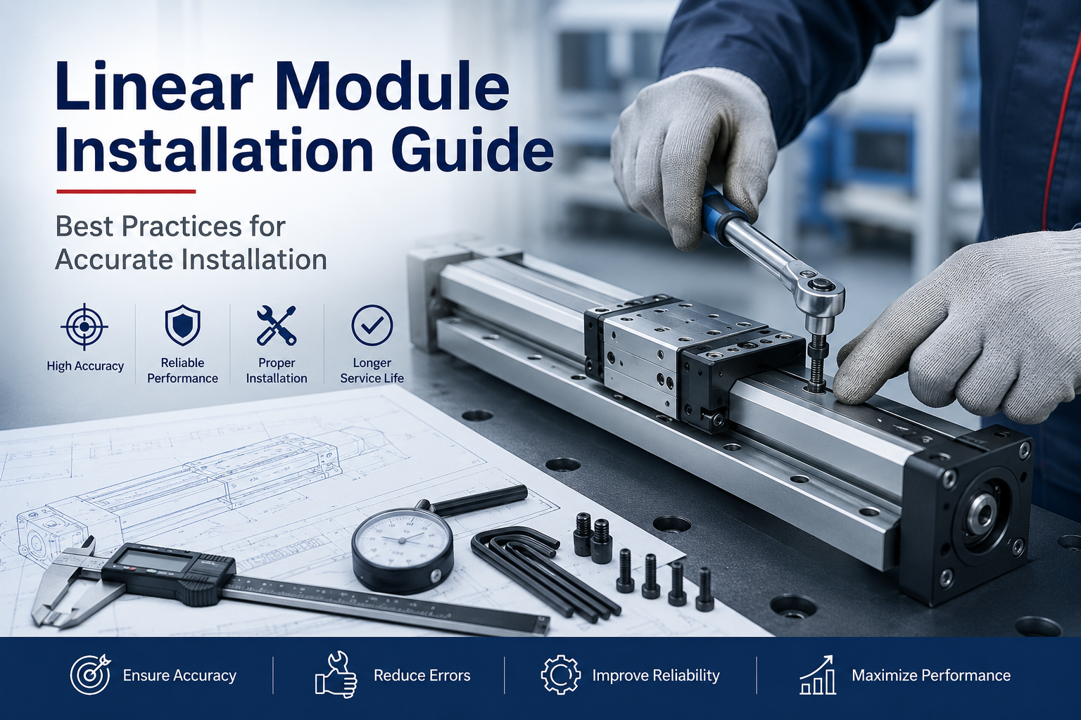
Why Proper Installation Matters
Many performance issues attributed to linear modules are actually caused by installation errors rather than product defects. Even small deviations during installation can introduce unnecessary stress into guide rails, bearings, and transmission components, significantly reducing operational performance.
Correct installation provides numerous benefits:
- Higher positioning accuracy
- Improved repeatability
- Reduced vibration
- Smoother motion
- Longer bearing life
- Lower maintenance costs
- Reduced energy consumption
- Improved equipment reliability
Conversely, improper installation may result in:
- Abnormal operating noise
- Premature guide rail wear
- Bearing damage
- Motor overload
- Coupling failure
- Positioning errors
- Servo alarms
- Unexpected machine downtime
Taking sufficient time during installation is therefore one of the most cost-effective methods of improving the long-term performance of an automation system.
The Complete Linear Module Installation Process
Professional equipment manufacturers generally follow a standardized installation procedure to ensure consistent quality and minimize installation-related problems.
- Prepare the installation environment.
- Inspect the linear module before installation.
- Verify the mounting surface.
- Install the linear module.
- Check alignment and parallelism.
- Install the motor.
- Install the coupling or transmission interface.
- Adjust sensors and limit switches.
- Route cables and drag chains.
- Commission the system.
- Perform final inspection.
Following each step in sequence helps prevent cumulative installation errors and simplifies commissioning later.
Step 1: Prepare the Installation Environment
Before unpacking the linear module, ensure that the installation area is clean, organized, and suitable for precision assembly. Dust, metal chips, moisture, and vibration during installation may negatively affect both assembly quality and long-term reliability.
Recommended Environmental Conditions
- Clean working area
- Stable ambient temperature
- Low humidity
- Minimal airborne dust
- Adequate lighting
- Sufficient assembly space
- Stable supporting structure
Whenever possible, precision linear modules should be assembled indoors under controlled environmental conditions.
Required Installation Tools
Preparing appropriate tools before installation improves efficiency and reduces the risk of accidental damage.
- Torque wrench
- Hex key set
- Dial indicator
- Precision straightedge
- Spirit level
- Feeler gauges
- Calipers
- Laser alignment tool (optional)
- Cleaning cloth
- Industrial alcohol
- Thread-locking compound
- Lubricant recommended by the manufacturer
Step 2: Inspect the Linear Module Before Installation
Every linear module should be thoroughly inspected before installation. Shipping damage, contamination, or missing components should be identified before the module is mounted onto the machine.
Visual Inspection Checklist
- Check for shipping damage.
- Verify model number.
- Confirm stroke length.
- Inspect guide rails.
- Inspect carriage movement.
- Check protective covers.
- Verify mounting holes.
- Inspect cable outlets.
- Check lubrication condition.
- Confirm all accessories are included.
The carriage should move smoothly by hand without noticeable binding, excessive resistance, or abnormal noise. Any irregularities should be investigated before continuing with installation.
Step 3: Verify Mounting Surface Requirements
The mounting surface serves as the foundation of the entire motion system. Regardless of how accurately the linear module is manufactured, installation on an uneven or insufficiently rigid surface will introduce distortion into the guide system.
Therefore, mounting surface quality is one of the most important factors affecting positioning accuracy and service life.
Surface Flatness
The mounting surface should be machined to provide adequate flatness over the entire installation length. Uneven mounting surfaces create internal stresses that increase friction and reduce guide rail life.
Surface Rigidity
The supporting structure should provide sufficient rigidity to prevent deformation under operating loads. Thin steel plates or flexible frames may require reinforcement before installation.
Surface Cleanliness
Before mounting the module, remove:
- Dust
- Oil
- Metal chips
- Rust
- Paint residue
- Burrs
Even small particles trapped beneath the module can create alignment errors that affect positioning performance.
Recommended Mounting Materials
| Material | Suitability |
|---|---|
| Machined Steel Plate | Excellent |
| Granite Base | Excellent |
| Cast Iron Frame | Excellent |
| Aluminum Plate | Good (with sufficient thickness) |
| Thin Sheet Metal | Not Recommended |
Step 4: Mount the Linear Module
Once the mounting surface has been verified, the linear module may be positioned on the machine base. Care should be taken to avoid impacts or twisting forces during handling.
Large modules should always be lifted using appropriate lifting equipment to prevent accidental damage.
Recommended Installation Procedure
- Position the module carefully on the mounting surface.
- Insert all mounting bolts loosely.
- Verify overall positioning.
- Tighten bolts gradually using a cross pattern.
- Apply the manufacturer's specified tightening torque.
- Recheck module alignment after tightening.
Bolts should never be fully tightened one at a time from one end to the other. Gradual tightening minimizes structural distortion and maintains guide rail alignment.
Step 5: Check Alignment
Accurate alignment is one of the most critical stages of linear module installation. Even if the mounting surface is flat and the module is securely fastened, poor alignment between the linear module and surrounding mechanical components can introduce excessive loads into the guide rails, bearings, drive mechanism, and motor.
Misalignment often causes increased friction, vibration, abnormal noise, uneven wear, reduced positioning accuracy, and shortened service life. These problems may not be immediately visible during commissioning but can gradually worsen during long-term operation.
Why Alignment Is Important
A linear module is designed to move along a precisely controlled straight path. Any external force attempting to twist, bend, or offset the carriage increases internal stress within the guide system.
Proper alignment helps ensure:
- Smooth linear motion
- Uniform bearing loading
- Reduced running resistance
- Higher positioning accuracy
- Longer bearing and guide rail life
- Improved servo stability
Recommended Alignment Tools
- Dial indicator
- Precision straightedge
- Laser alignment system
- Digital level
- Granite square
For high-precision applications such as semiconductor manufacturing or optical inspection systems, laser alignment equipment is recommended to achieve the highest installation accuracy.
Alignment Procedure
- Secure the module loosely on the mounting surface.
- Establish a reference edge or datum.
- Measure carriage movement along the full stroke.
- Identify any deviation from the reference line.
- Adjust module position gradually.
- Repeat measurements until acceptable tolerance is achieved.
- Fully tighten mounting bolts according to the specified torque.
Alignment should always be verified after final bolt tightening because fastening forces may slightly shift the module position.
Step 6: Verify Parallelism
Applications using dual linear modules or multi-axis motion systems require accurate parallelism between guide systems. Poor parallelism causes the moving platform to bind during travel, increasing friction and placing excessive loads on bearings and motors.
Parallelism is particularly important for:
- Cartesian robots
- Gantry systems
- Dual-axis transport systems
- Large automation platforms
- High-load positioning systems
Typical Causes of Poor Parallelism
- Uneven mounting surfaces
- Incorrect machining tolerances
- Improper bolt tightening sequence
- Frame deformation
- Assembly errors
Checking Parallelism
Parallelism can be evaluated by measuring the distance between reference surfaces at multiple positions throughout the stroke. Any significant variation indicates that adjustment is required.
For long-stroke applications, measurements should be taken near both ends as well as several intermediate locations.
Effects of Poor Parallelism
| Problem | Possible Result |
|---|---|
| Guide rail binding | Increased friction |
| Uneven bearing loading | Premature wear |
| Motor overload | Servo alarms |
| Platform distortion | Reduced positioning accuracy |
| High running resistance | Reduced efficiency |
Whenever possible, parallelism should be confirmed before connecting multiple modules to a common moving platform.
Step 7: Install the Motor
After the mechanical installation has been completed, the drive motor can be installed. Correct motor installation ensures efficient power transmission and stable motion throughout the operating range.
The motor should never be forced into position. Misalignment between the motor shaft and transmission mechanism can damage bearings, couplings, and motor shafts.
Before Motor Installation
- Verify the motor model.
- Confirm shaft dimensions.
- Inspect the motor flange.
- Check mounting holes.
- Ensure all mating surfaces are clean.
Motor Installation Procedure
- Position the motor carefully.
- Align the motor shaft with the transmission input.
- Insert mounting bolts by hand.
- Tighten bolts gradually using a diagonal sequence.
- Apply the specified tightening torque.
- Rotate the system manually to verify smooth movement.
After installation, the motor should rotate freely without noticeable resistance or abnormal vibration.
Motor Mount Inspection
Verify the following items before electrical commissioning:
- Motor flange sits flush.
- No visible gaps exist.
- Bolts are tightened correctly.
- Motor shaft rotates smoothly.
- No interference with surrounding components.
Step 8: Install the Coupling
The coupling connects the motor shaft to the drive mechanism and plays an important role in transmitting torque while compensating for minor alignment errors. Improper coupling installation is one of the most common causes of vibration and premature bearing failure.
Common Coupling Types
- Flexible jaw coupling
- Bellows coupling
- Disc coupling
- Oldham coupling
- Rigid coupling
The appropriate coupling depends on torque requirements, positioning accuracy, operating speed, and allowable shaft misalignment.
Coupling Installation Procedure
- Clean both shafts thoroughly.
- Install the coupling halves separately.
- Maintain the recommended shaft insertion depth.
- Leave the specified axial clearance.
- Tighten clamping screws gradually.
- Verify concentricity.
- Rotate the assembly manually.
Common Coupling Installation Mistakes
- Forcing the shafts together.
- Eliminating the required axial gap.
- Overtightening clamping screws.
- Using damaged couplings.
- Ignoring shaft misalignment.
These mistakes can significantly reduce coupling life and increase vibration throughout the motion system.
Step 9: Adjust Sensors and Limit Switches
Position sensors and limit switches protect the motion system while providing accurate position feedback to the controller. Correct adjustment is essential for reliable machine operation and operator safety.
Typical Sensor Types
- Inductive proximity sensors
- Magnetic sensors
- Photoelectric sensors
- Mechanical limit switches
- Home position sensors
Sensor Installation Guidelines
- Install sensors securely.
- Maintain recommended sensing distance.
- Avoid cable interference.
- Protect sensors from impact.
- Verify repeatable triggering.
After adjustment, manually move the carriage through the complete stroke to confirm that all sensors trigger consistently at the intended positions.
Step 10: Cable Routing and Drag Chain Installation
Proper cable management protects electrical cables, pneumatic tubing, and communication lines from excessive bending, abrasion, and fatigue during repeated motion. Poor cable routing can lead to intermittent electrical faults, communication failures, or premature cable breakage.
Cable Routing Best Practices
- Use appropriately sized drag chains.
- Separate power and signal cables.
- Maintain the minimum bending radius.
- Avoid excessive cable tension.
- Prevent cable twisting.
- Secure cables at both ends.
- Allow sufficient movement margin.
Cables should move freely inside the drag chain without excessive compression or entanglement throughout the entire stroke.
Common Cable Routing Errors
- Overfilling the drag chain.
- Using cables with insufficient flexibility.
- Ignoring minimum bend radius.
- Mixing high-voltage and encoder cables.
- Leaving unsupported cable loops.
Correct cable routing not only improves reliability but also simplifies future maintenance and troubleshooting.
Step 11: Commission the Linear Module
After the mechanical and electrical installation has been completed, the linear module should undergo a systematic commissioning process before entering normal operation. Commissioning verifies that all mechanical, electrical, and control components work together correctly while minimizing the risk of equipment damage during initial startup.
The commissioning process should always begin at low speed and gradually progress to the intended operating conditions. Avoid commanding maximum speed or acceleration until every function has been verified.
Initial Commissioning Procedure
- Verify that all mounting bolts are tightened to the specified torque.
- Confirm that the carriage can move freely by hand where applicable.
- Check that all cables and drag chains move without interference.
- Power on the control system.
- Verify motor direction.
- Perform homing or reference positioning.
- Run the module at low speed.
- Gradually increase speed and acceleration.
- Verify sensor operation.
- Check positioning accuracy and repeatability.
Each step should be completed successfully before proceeding to the next. Any abnormal behavior should be investigated immediately rather than continuing with commissioning.
Motion Verification
After commissioning, the complete motion profile should be verified to ensure stable and repeatable performance throughout the entire stroke.
Items to Verify
- Smooth acceleration
- Smooth deceleration
- Consistent travel speed
- No abnormal vibration
- No unusual operating noise
- Stable positioning accuracy
- Repeatable homing position
- Proper emergency stop function
The carriage should travel smoothly from one end of the stroke to the other without sticking, oscillation, or unexpected resistance.
Lubrication Before Operation
Although many linear modules are supplied pre-lubricated, lubrication should always be verified before placing the equipment into production. Proper lubrication minimizes friction, reduces wear, and extends the service life of guide rails, bearings, and transmission components.
Lubrication Checklist
- Verify lubricant type.
- Check lubrication quantity.
- Lubricate guide rails if required.
- Lubricate ball screw assemblies where applicable.
- Inspect automatic lubrication systems.
- Remove excess lubricant.
Always use the lubricant recommended by the manufacturer. Mixing incompatible lubricants may reduce lubrication performance and shorten component life.
Final Installation Checklist
Before the machine is released for production, a comprehensive inspection should be performed to ensure that every installation step has been completed correctly.
| Inspection Item | Status |
|---|---|
| Installation surface inspected | □ |
| Module securely mounted | □ |
| Alignment verified | □ |
| Parallelism confirmed | □ |
| Motor installed correctly | □ |
| Coupling installed correctly | □ |
| Sensors adjusted | □ |
| Cable routing completed | □ |
| Lubrication verified | □ |
| Motion test completed | □ |
| Emergency stop verified | □ |
| Positioning accuracy confirmed | □ |
| Repeatability verified | □ |
| Safety guards installed | □ |
| Documentation completed | □ |
Common Linear Module Installation Mistakes
Even experienced technicians can encounter installation issues if recommended procedures are not followed carefully. The following mistakes are among the most common causes of reduced performance and premature component failure.
- Installing the module on an uneven mounting surface.
- Ignoring mounting surface rigidity.
- Tightening bolts in an incorrect sequence.
- Applying excessive bolt torque.
- Using damaged mounting hardware.
- Failing to verify alignment.
- Ignoring parallelism in dual-axis systems.
- Installing the motor under mechanical stress.
- Incorrect coupling installation.
- Using incompatible lubricants.
- Improper cable routing.
- Insufficient drag chain capacity.
- Poor sensor positioning.
- Skipping low-speed commissioning.
- Operating without checking repeatability.
- Ignoring abnormal noise during testing.
- Running the system without adequate lubrication.
- Failing to retighten fasteners after initial operation.
- Neglecting safety devices.
- Ignoring manufacturer installation recommendations.
Avoiding these common mistakes greatly improves long-term reliability and reduces maintenance costs throughout the equipment lifecycle.
Best Practices for Linear Module Installation
Experienced automation manufacturers follow standardized installation practices to achieve consistent motion quality across every machine they build.
- Always install on a precision-machined mounting surface.
- Use calibrated torque tools.
- Keep all components clean during assembly.
- Check alignment before and after tightening bolts.
- Verify smooth manual movement before powering the system.
- Separate power cables from signal cables.
- Perform gradual commissioning from low speed to full speed.
- Record installation measurements for future maintenance.
- Establish a preventive maintenance schedule immediately after installation.
Following standardized installation procedures improves equipment consistency while reducing troubleshooting time during commissioning.
Maintenance After Installation
Installation marks the beginning of the linear module's service life rather than the end of the setup process. Regular inspection and preventive maintenance help preserve positioning accuracy and maximize component longevity.
Recommended maintenance activities include:
- Inspect fastener tightness periodically.
- Lubricate according to the maintenance schedule.
- Clean guide rails and protective covers.
- Inspect drag chains for wear.
- Check cable condition.
- Verify sensor operation.
- Monitor abnormal vibration.
- Measure positioning repeatability.
- Inspect couplings and motor mounting.
Establishing preventive maintenance intervals based on operating hours rather than waiting for failures significantly improves machine availability.
Frequently Asked Questions
Can a linear module be installed on a welded frame?
Yes, provided the mounting surface is properly machined after welding to achieve sufficient flatness and rigidity.
Should mounting bolts be tightened all at once?
No. Bolts should be tightened gradually using a cross or diagonal sequence to minimize distortion and maintain alignment.
How important is mounting surface flatness?
It is one of the most important installation factors. An uneven mounting surface can introduce internal stress, increase friction, reduce positioning accuracy, and shorten guide rail life.
Do all linear modules require lubrication before use?
Many modules are supplied pre-lubricated, but lubrication should always be verified before commissioning and maintained according to the manufacturer's recommendations.
Why is low-speed commissioning recommended?
Low-speed testing allows installation problems to be identified safely before the system operates under full load or maximum acceleration.
What causes abnormal vibration after installation?
Common causes include poor alignment, insufficient mounting rigidity, incorrect coupling installation, improper motor tuning, loose fasteners, or cable interference.
How often should installation accuracy be rechecked?
For high-precision equipment, alignment and fastening torque should be rechecked after initial operation and then periodically according to the maintenance schedule.
Conclusion
Proper installation is essential for achieving the full performance of a linear module. Accurate mounting, careful alignment, correct motor installation, appropriate cable management, and systematic commissioning all contribute to higher positioning accuracy, smoother motion, longer service life, and lower maintenance costs.
By following a structured installation process and applying industry best practices, engineers can minimize installation-related problems while maximizing the reliability and efficiency of automation equipment. Whether the application involves timing belt modules, ball screw modules, rack-and-pinion systems, or linear motor stages, careful installation provides the foundation for long-term, stable, and precise linear motion.
A well-installed linear module not only improves current machine performance but also simplifies future maintenance, troubleshooting, and system upgrades, ensuring reliable operation throughout the entire lifecycle of the equipment.
