 English

Selecting the rightlinear moduleis one of the most important decisions in any automation project. A properly selected module improves positioning accuracy, production efficiency, equipment reliability, and service life, while an unsuitable selection may lead to vibration, insufficient thrust, poor repeatability, premature wear, and unexpected maintenance costs.
Modern linear modules are widely used in CNC machine tools, semiconductor manufacturing, lithium battery production, electronics assembly, medical equipment, packaging machinery, vision inspection systems, laboratory automation, andCartesian robots. Every application has different performance requirements, making the selection process far more than simply choosing a travel distance or motor size.
A successful selection requires engineers to evaluate mechanical loads, stroke length, motion profiles, positioning accuracy, operating environment, duty cycle, installation direction, available installation space, motor compatibility, and future expansion requirements. Understanding how these factors interact allows designers to achieve the optimal balance between performance, cost, reliability, and maintenance.
This guide explains every major consideration involved in linear module selection, from defining application requirements to selecting the appropriate drive mechanism. Whether designing a new automation system or upgrading existing equipment, this article provides a practical framework for choosing the most suitable linear module.
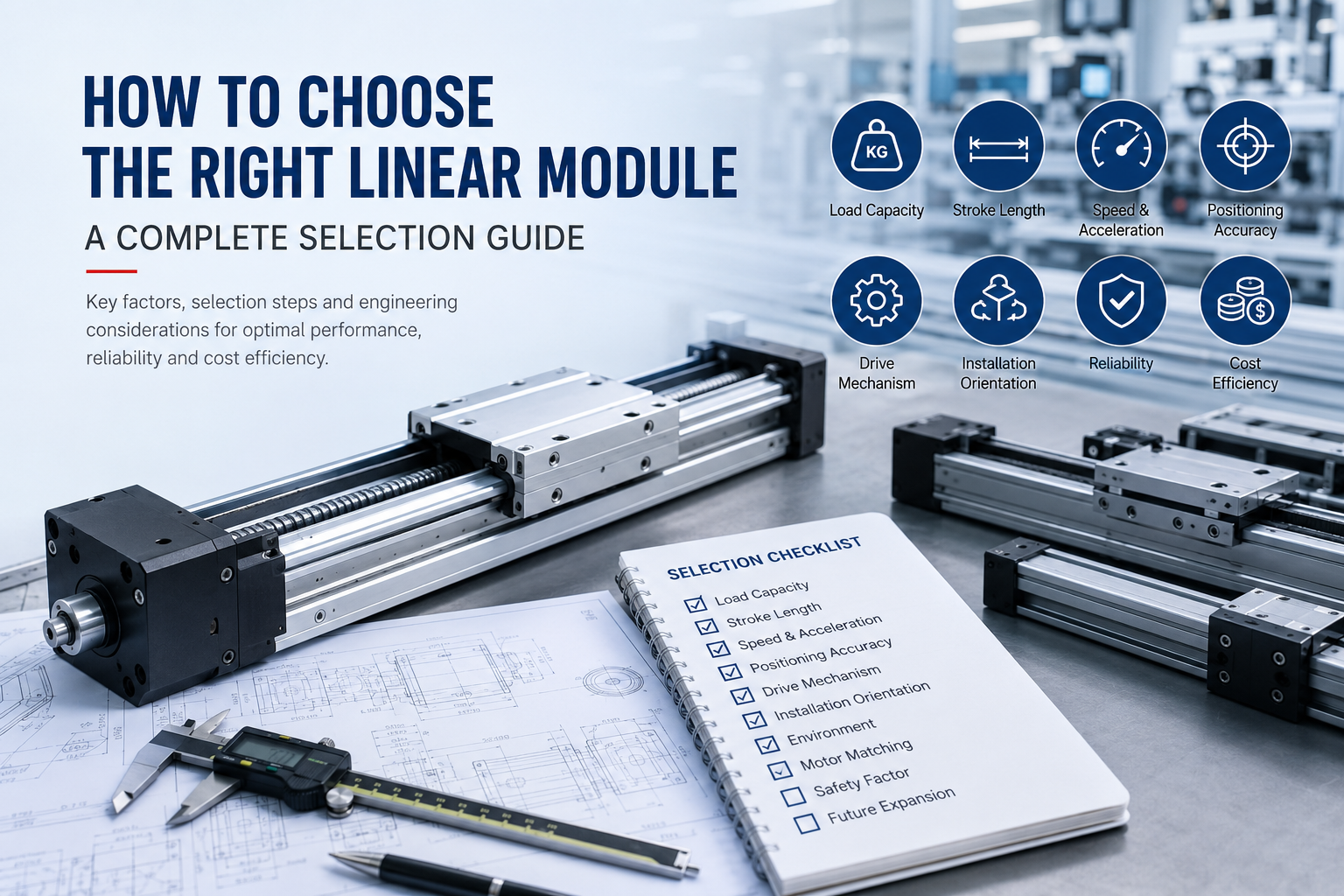
Why Proper Linear Module Selection Matters
Many automation problems originate not from manufacturing defects but from improper product selection during the design stage. Choosing a module with insufficient load capacity, inadequate rigidity, or unsuitable drive technology often causes performance limitations that cannot be corrected after installation.
Proper selection provides several important benefits:
- Higher positioning accuracy
- Longer service life
- Lower maintenance costs
- Improved production efficiency
- Better motion stability
- Reduced machine vibration
- Lower energy consumption
- Greater system reliability
Conversely, an oversized module increases equipment cost, occupies unnecessary installation space, requires larger motors, and often reduces overall system efficiency. The objective is therefore not selecting the biggest module, but selecting the most appropriate one.
The Complete Linear Module Selection Process
Professional automation engineers typically follow a structured selection procedure rather than choosing products based solely on payload or travel distance. Each design parameter influences subsequent decisions, making the selection process systematic rather than independent.
- Define the application requirements.
- Determine payload characteristics.
- Calculate total moving mass.
- Determine stroke length.
- Calculate required speed and acceleration.
- Define positioning accuracy requirements.
- Select the appropriate drive mechanism.
- Evaluate installation orientation.
- Analyze environmental conditions.
- Select a compatible motor.
- Verify safety factors.
- Review future expansion requirements.
Following this sequence minimizes design errors and ensures that all important engineering factors are considered before finalizing the module specification.
Step 1: Clearly Define the Application Requirements
Before selecting any mechanical specifications, engineers should first understand the purpose of the linear motion system. Different industries prioritize different performance characteristics, and these priorities directly affect module selection.
Typical Questions to Answer
- What task will the module perform?
- Is the motion horizontal or vertical?
- Will positioning or continuous movement be required?
- How many operating cycles occur every hour?
- What production throughput is expected?
- What is the expected equipment lifetime?
- Will the module operate continuously or intermittently?
- Does the application require synchronized multi-axis motion?
These questions establish the overall design objectives before detailed engineering calculations begin.
Common Automation Applications
| Application | Primary Requirement |
|---|---|
| Pick and Place | High speed and repeatability |
| CNC Loading | Heavy load capacity |
| Vision Inspection | High positioning accuracy |
| Laser Processing | Smooth motion and precision |
| Packaging Machinery | Fast cycle times |
| Semiconductor Equipment | Cleanroom compatibility |
| Medical Automation | Low noise and high reliability |
| Battery Manufacturing | Continuous operation with high stability |
Understanding the application objective helps prioritize which specifications deserve the greatest attention during the remaining selection process.
Step 2: Determine Load Capacity
Load capacity is often considered the most important parameter in linear module selection because every moving component must be safely supported throughout the entire operating cycle.
However, engineers frequently misunderstand payload specifications. The moving object alone does not represent the total load acting on the module.
What Makes Up the Total Load?
The actual moving load normally includes multiple components:
- Workpiece weight
- Fixture weight
- End effector or tooling
- Mounting plate
- Cables and hoses
- Sensors
- Vacuum generators
- Additional moving accessories
Every moving component contributes to inertia, influencing acceleration, motor sizing, and structural rigidity.
Static Load vs Dynamic Load
Two different loading conditions must always be evaluated.
Static Load
Static load represents the force acting on the module while stationary. This affects structural safety, guide rail deformation, and bearing life.
Dynamic Load
Dynamic load occurs during acceleration, deceleration, and continuous motion. Because inertial forces increase with acceleration, dynamic loads are often considerably larger than the static payload.
For high-speed automation systems, dynamic loading usually becomes the dominant design factor.
Load Direction Matters
Linear modules experience different mechanical stresses depending on installation orientation.
- Horizontal installation mainly experiences guide rail loading.
- Vertical installation requires continuous gravity compensation.
- Wall-mounted systems introduce overturning moments.
- Ceiling-mounted installations create additional safety considerations.
Selecting a module without considering installation direction may significantly reduce bearing life and positioning stability.
Step 3: Determine the Required Stroke Length
Stroke length defines the maximum travel distance that the carriage must move during operation. Although selecting stroke appears straightforward, engineers should avoid choosing the exact travel distance without considering additional design margins.
A proper stroke calculation typically includes:
- Working travel distance
- Acceleration zone
- Deceleration zone
- Safety clearance
- Sensor installation space
- Mechanical buffer allowance
For example, if a workpiece must move 600 mm between two stations, the selected module may require a stroke of approximately 700–800 mm after including acceleration distance and safety margins.
Selecting an unnecessarily long stroke increases structural deflection, manufacturing cost, and occupied machine space. Conversely, selecting an insufficient stroke limits production flexibility and may require complete mechanical redesign later.
Step 4: Evaluate Speed and Acceleration Requirements
Production efficiency depends heavily on motion speed, but maximum speed alone is rarely the determining factor. Acceleration, deceleration, settling time, and cycle time together define the overall productivity of the automation system.
High acceleration allows equipment to reach operating speed more quickly, reducing cycle time even when maximum speed remains unchanged.
However, increasing acceleration also increases:
- Motor torque requirements
- Drive force
- Mechanical vibration
- Bearing loads
- Structural stress
- Energy consumption
Therefore, selecting the highest possible acceleration is not always beneficial. Instead, engineers should balance productivity with equipment longevity and positioning stability.
Applications involving vision inspection or precision dispensing may intentionally use lower acceleration profiles to minimize vibration, while pick-and-place robots often prioritize aggressive acceleration to maximize throughput.
Step 5: Determine the Required Positioning Accuracy
Positioning accuracy is one of the most critical selection criteria for a linear module. Different automation tasks require different levels of precision, and specifying unnecessarily high accuracy often increases equipment cost without providing practical benefits. Conversely, selecting a module with insufficient accuracy may lead to poor product quality, assembly errors, or failed inspection processes.
When evaluating positioning performance, engineers should distinguish between several different accuracy specifications rather than treating them as a single value.
Positioning Accuracy
Positioning accuracy describes how closely the carriage reaches the commanded target position. It represents the difference between the programmed position and the actual position after movement.
Repeatability
Repeatability measures the ability of the module to return to the same position repeatedly under identical operating conditions. In industrial automation, repeatability is often more important than absolute positioning accuracy because production equipment performs repetitive movements throughout its service life.
For example, a pick-and-place robot that repeatedly transfers components between fixed locations relies primarily on repeatability rather than absolute positioning accuracy.
Resolution
Resolution refers to the smallest movement increment that the control system can command. Resolution depends on the motor, encoder, transmission mechanism, and controller rather than the linear module alone.
Straightness
Straightness measures how accurately the carriage follows a straight path during travel. This parameter becomes particularly important in laser processing, dispensing, optical inspection, and semiconductor manufacturing.
Typical Accuracy Requirements
| Application | Typical Repeatability |
|---|---|
| Packaging Equipment | ±0.10 mm |
| General Material Handling | ±0.05 mm |
| Electronics Assembly | ±0.02 mm |
| Vision Inspection | ±0.01 mm |
| CNC Automation | ±0.01 mm |
| Semiconductor Equipment | ±0.005 mm or better |
| Precision Measurement | Micron-level repeatability |
Selecting precision significantly beyond application requirements generally increases equipment cost, motor requirements, controller complexity, and maintenance difficulty without improving production efficiency.
Step 6: Select the Appropriate Drive Mechanism
The drive mechanism determines how rotary motor motion is converted into linear movement. Each transmission technology offers different advantages in terms of speed, accuracy, load capacity, maintenance, and cost.
Choosing the correct drive type is therefore one of the most influential decisions during module selection.
Ball Screw Linear Modules
Ball screw linear modulesuse recirculating steel balls between the screw shaft and nut to convert rotational motion into highly accurate linear movement with minimal friction.
Advantages
- Excellent positioning accuracy
- High repeatability
- High thrust force
- Minimal backlash
- Suitable for precision positioning
Limitations
- Lower maximum speed
- Limited stroke length
- Higher manufacturing cost
- Lubrication required
Typical Applications
- Semiconductor equipment
- CNC machinery
- Medical devices
- Precision assembly
- Vision inspection
Timing Belt Linear Modules
Timing belt linear modules transmit power through reinforced synchronous belts. They provide excellent travel speed and long stroke capability while maintaining relatively simple mechanical construction.
Advantages
- Very high travel speed
- Long stroke capability
- Lower overall cost
- Smooth continuous movement
- Low maintenance requirements
Limitations
- Lower positioning accuracy than ball screws
- Elastic belt deformation under heavy loads
- Periodic belt replacement may be required
Typical Applications
- Packaging machinery
- Material handling
- Automated production lines
- Pick and place systems
- Warehouse automation
Rack and Pinion Linear Modules
Rack and pinion systems are commonly selected for applications requiring extremely long travel distances and heavy payloads.
Advantages
- Unlimited practical stroke length
- Suitable for heavy loads
- High operating speed
- Excellent scalability
Limitations
- Lower positioning precision
- Requires backlash management
- Higher installation requirements
Typical Applications
- Large gantry systems
- Heavy industrial automation
- Machine loading
- Automated welding
Linear Motor Modules
Linear motor modules eliminate mechanical transmission components entirely by generating direct electromagnetic linear motion.
Advantages
- Highest positioning accuracy
- No mechanical backlash
- Ultra-high acceleration
- Exceptional dynamic response
- Very low maintenance
Limitations
- Highest purchase cost
- Requires sophisticated servo control
- Greater thermal management requirements
Typical Applications
- Semiconductor manufacturing
- High-speed inspection
- Laser machining
- Optical positioning
- Precision manufacturing
Drive Type Comparison
| Drive Type | Speed | Accuracy | Stroke | Load | Cost |
|---|---|---|---|---|---|
| Ball Screw | Medium | Excellent | Short to Medium | High | High |
| Timing Belt | Excellent | Good | Long | Medium | Low |
| Rack and Pinion | High | Medium | Very Long | Very High | Medium |
| Linear Motor | Excellent | Excellent | Medium to Long | Medium | Very High |
Step 7: Evaluate the Installation Environment
Environmental conditions directly affect the reliability, service life, and maintenance requirements of a linear module. Selecting a module without considering its operating environment may result in contamination, corrosion, premature wear, or unexpected failures.
Dust and Particles
Woodworking equipment, cutting machinery, mining equipment, and construction automation often generate significant airborne dust. Dust entering guide rails or ball screws accelerates wear and increases friction.
For dusty environments, enclosed linear modules or protective covers are generally recommended.
Water and Coolant Exposure
Machining centers, food processing equipment, and washing systems frequently expose linear modules to water, cutting fluid, or cleaning chemicals. Corrosion-resistant materials, stainless steel components, and effective sealing systems improve durability under these conditions.
Temperature
Extreme temperatures influence lubricant performance, thermal expansion, and positioning accuracy. High temperatures may reduce grease life, while low temperatures increase lubricant viscosity and drive resistance.
When operating outside standard industrial temperature ranges, engineers should verify component specifications and lubrication recommendations.
Cleanroom Applications
Semiconductor manufacturing, pharmaceutical production, and laboratory automation require exceptionally clean operating environments. Modules intended for cleanroom use often incorporate enclosed structures, low-particle lubrication, cable management systems, and sealed guide mechanisms to minimize contamination.
Corrosive Environments
Chemical processing plants, marine automation, and battery manufacturing may expose equipment to corrosive gases or liquids. Appropriate material selection, protective coatings, and stainless steel components improve long-term reliability.
Step 8: Select a Compatible Motor
A linear module cannot perform effectively without a properly matched motor. The motor determines acceleration capability, positioning performance, motion smoothness, and overall system responsiveness.
Motor selection should always consider the mechanical characteristics of the selected module rather than treating the two components independently.
Stepper Motors
Stepper motors provide simple open-loop motion control and are widely used in economical automation systems requiring moderate speed and positioning accuracy.
Advantages
- Low cost
- Simple control architecture
- Good low-speed torque
- Easy integration
Limitations
- Possible missed steps
- Lower efficiency
- Reduced high-speed performance
- Higher vibration levels
Servo Motors
Servo motors operate using closed-loop feedback, allowing highly accurate position, speed, and torque control.
Advantages
- Excellent positioning accuracy
- High acceleration capability
- Smooth motion
- Automatic position correction
- High operating efficiency
Typical Applications
- High-speed automation
- Precision assembly
- CNC equipment
- Robotics
- Semiconductor manufacturing
Motor Matching Considerations
Selecting the correct motor involves much more than matching the motor flange to the linear module. Engineers should evaluate the entire motion system to ensure the motor can deliver sufficient torque, speed, and acceleration while maintaining stable operation throughout the machine's service life.
The following parameters should be verified during motor selection:
- Total moving mass
- Required maximum speed
- Acceleration and deceleration profile
- Duty cycle
- Required positioning accuracy
- Available power supply
- Controller compatibility
- Brake requirements for vertical applications
For vertical installations, servo motors equipped with holding brakes are generally recommended to prevent the carriage from moving under gravity when power is removed.
In high-speed automation systems, motor inertia matching is equally important. Excessive inertia mismatch can reduce system responsiveness, increase vibration, and make servo tuning more difficult.
Step 9: Consider Installation Orientation
Installation orientation directly affects the forces acting on the guide system, transmission mechanism, bearings, and motor. A module that performs well in a horizontal application may require a different configuration when installed vertically or overhead.
Horizontal Installation
Horizontal mounting is the most common configuration because gravity acts perpendicular to the direction of motion. The module mainly supports the payload while the drive system is responsible for acceleration and positioning.
Vertical Installation
Vertical motion introduces continuous gravitational loading. The drive mechanism must not only accelerate the payload but also overcome gravity during upward movement and safely control descent during downward travel.
For vertical applications, engineers should carefully evaluate:
- Continuous thrust requirements
- Holding brake requirements
- Safety factor against back-driving
- Emergency stop performance
- Load balancing options
Wall-Mounted Installation
Wall-mounted systems create overturning moments that increase loading on the guide bearings. Modules with higher moment capacity and greater structural rigidity are generally preferred.
Overhead Installation
Ceiling-mounted applications require additional attention to safety. Mechanical locking devices, redundant braking systems, and higher safety factors may be necessary depending on the application.
Step 10: Evaluate Duty Cycle and Service Life
A linear module operating continuously in a high-speed production line experiences significantly different wear conditions than one used occasionally in laboratory equipment. Therefore, engineers should estimate the expected duty cycle during the design phase.
Important Questions
- How many cycles occur each minute?
- How many operating hours are expected each day?
- Will the machine operate continuously?
- How many years of service are required?
- What maintenance intervals are acceptable?
Higher duty cycles generally require:
- Higher-quality guide rails
- Improved lubrication systems
- More durable transmission components
- Higher-capacity bearings
- Better sealing against contaminants
Considering service life early in the selection process helps reduce long-term maintenance costs and improve production availability.
Step 11: Plan for Future Expansion
Automation systems frequently evolve after installation. Production capacity may increase, product dimensions may change, or additional processing stations may be added. Selecting a linear module with limited upgrade potential can make future modifications expensive and time-consuming.
When possible, engineers should consider:
- Future payload increases
- Additional travel requirements
- Higher production speeds
- Additional sensors
- Extra tooling
- Integration with robotic systems
- Expansion to multi-axis configurations
Designing with moderate expansion capability often provides a lower total cost of ownership over the equipment's lifecycle.
Linear Module Selection Examples
Example 1: High-Speed Packaging Line
A packaging machine requires rapid movement between multiple stations with a travel distance of 1.5 meters and moderate payloads.
Recommended characteristics:
- Timingbelt linear module
- Long stroke capability
- High acceleration
- Servo motor
- Moderate positioning accuracy
Example 2: CNC Machine Loading
A CNC loading system transfers heavy metal workpieces between storage racks and machining centers.
Recommended characteristics:
- Ball screw module
- High load capacity
- High rigidity
- Servo motor
- Protective covers against chips
Example 3: Semiconductor Inspection
An optical inspection platform requires micron-level positioning with extremely smooth motion.
Recommended characteristics:
- Linear motor module
- High-resolution encoder
- Ultra-high repeatability
- Cleanroom-compatible design
- Low-vibration structure
Example 4: Warehouse Automation
An automated storage system transports products over long distances while maintaining high throughput.
Recommended characteristics:
- Timing belt or rack-and-pinion module
- Long stroke
- High travel speed
- Moderate precision
- Low maintenance design
Linear Module Selection Checklist
Before finalizing a linear module specification, engineers should verify the following items:
| Selection Item | Status |
|---|---|
| Application requirements defined | □ |
| Total moving load calculated | □ |
| Stroke length confirmed | □ |
| Maximum speed verified | □ |
| Acceleration determined | □ |
| Repeatability requirement confirmed | □ |
| Drive mechanism selected | □ |
| Installation direction evaluated | □ |
| Operating environment reviewed | □ |
| Motor compatibility verified | □ |
| Safety factor confirmed | □ |
| Maintenance requirements reviewed | □ |
| Future expansion considered | □ |
Common Linear Module Selection Mistakes
Many automation projects experience unnecessary performance issues because important selection factors are overlooked during system design.
The following mistakes are among the most common:
- Selecting a module based only on payload weight.
- Ignoring acceleration-induced dynamic loads.
- Choosing unnecessary ultra-high positioning accuracy.
- Underestimating required stroke length.
- Ignoring installation orientation.
- Using timing belt modules where precision ball screws are required.
- Selecting ball screw modules for extremely long travel applications.
- Ignoring environmental contamination.
- Improper servo motor sizing.
- Failing to consider future production expansion.
Avoiding these common mistakes significantly improves equipment reliability and reduces redesign costs.
Frequently Asked Questions
Should I always choose the highest accuracy available?
No. The required positioning accuracy should match the application's actual production requirements. Excessively high precision usually increases cost without improving manufacturing efficiency.
Which drive type is best for long travel distances?
Timing belt and rack-and-pinion systems are generally better suited for long-stroke applications than ball screw modules.
Are servo motors always better than stepper motors?
Servo motors provide superior speed, positioning performance, and dynamic response, but stepper motors remain an economical solution for many light-duty automation systems.
Can one linear module be used for every application?
No. Every application has unique requirements involving speed, load, precision, environment, and duty cycle. Module selection should always be application-specific.
How important is repeatability?
For most industrial automation systems, repeatability is more important than absolute positioning accuracy because production relies on consistent repetitive motion.
When should a linear motor module be selected?
Linear motor modules are preferred when applications demand extremely high speed, high acceleration, exceptional positioning accuracy, and minimal mechanical wear.
Conclusion
Choosing the right linear module requires a comprehensive evaluation of mechanical, electrical, and application-specific requirements rather than focusing on a single specification. Load capacity, stroke length, positioning accuracy, travel speed, drive mechanism, installation orientation, environmental conditions, motor compatibility, and expected service life all influence the overall performance of the motion system.
A structured selection process helps engineers balance precision, productivity, reliability, and cost while minimizing future maintenance and redesign. Whether the application involves high-speed packaging, precision semiconductor manufacturing, CNC automation, robotics, or laboratory equipment, selecting the most appropriate linear module ensures stable operation and maximizes the return on investment throughout the equipment lifecycle.
As industrial automation continues to advance toward higher precision, greater flexibility, and smarter manufacturing, careful linear module selection remains the foundation of efficient and reliable motion control systems.
