 English

The structure of alinear moduleis designed to convert rotary or electromagnetic power into smooth, accurate, and repeatable linear motion. Unlike a simple linear guide or actuator, a complete linear module integrates multiple mechanical and control components into one compact motion platform. These components work together to achieve high positioning accuracy, excellent rigidity, long service life, and reliable automation performance.
Understanding the internal structure of a linear module is essential when selecting equipment for industrial automation. Each structural component directly influences load capacity, motion accuracy, maximum speed, repeatability, maintenance requirements, and installation flexibility. Whether the module is driven by a ball screw, timing belt, rack and pinion, or linear motor, the overall mechanical architecture remains remarkably similar.
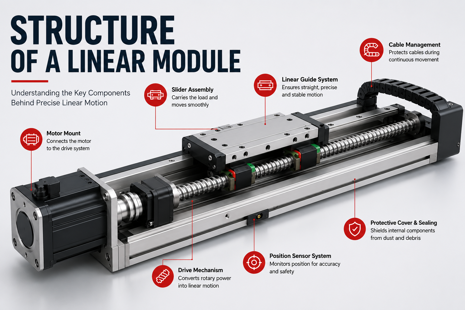
A standard linear module typically consists of the following structural assemblies:
- Base frame
- Linear guide system
- Drive mechanism
- Slider (carriage)
- Motor mounting system
- Position sensing system
- Cable management system
- Protective cover and sealing components
- Lubrication system
- Mechanical limit devices
Each component performs a specific function, and together they form a complete linear motion system capable of delivering precise, stable, and efficient movement in demanding industrial environments.
Overall Structural Layout of a Linear Module
From an engineering perspective, a linear module is built around a rigid mechanical framework that supports the guide rails and drive system while maintaining dimensional stability throughout operation.
Although different manufacturers may adopt unique design details, the basic structural arrangement usually follows the same sequence:
- The motor generates rotational or electromagnetic power.
- The drive mechanism converts power into linear movement.
- The slider travels along precision linear guide rails.
- The guide system supports external loads while maintaining positioning accuracy.
- Sensors monitor the carriage position.
- The cable management system protects electrical connections during continuous movement.
- The base frame maintains structural rigidity and installation precision.
Because every subsystem is mechanically integrated, the linear module becomes a highly compact motion platform requiring significantly less installation work than assembling individual components separately.
Base Frame: The Structural Foundation
The base frame serves as the backbone of the entire linear module. Every other component—including guide rails, drive mechanisms, motor mounts, sensors, and protective covers—is installed on this structural member.
Its primary responsibilities include:
- Supporting all mechanical loads
- Maintaining geometric accuracy
- Preventing structural deformation
- Reducing vibration during motion
- Providing installation reference surfaces
Since the base frame directly affects positioning accuracy, manufacturers typically use high-strength materials combined with precision machining processes.
Common Base Frame Materials
| Material | Main Advantages | Typical Applications |
|---|---|---|
| Aluminum Alloy | Lightweight, corrosion resistant, easy machining | General industrial automation |
| Steel | Excellent rigidity and heavy load capacity | Heavy-duty machinery |
| Cast Iron | Superior vibration damping | Ultra-high precision equipment |
| Composite Materials | Thermal stability and weight reduction | Specialized automation systems |
Among these options, anodized aluminum extrusion is the most common solution for industrial linear modules because it provides an excellent balance between rigidity, weight, manufacturing cost, and corrosion resistance.
Structural Features of the Base Frame
A well-designed base frame includes numerous engineering details that improve overall system performance.
- Precision-machined guide rail mounting surfaces
- Motor mounting interfaces
- Integrated cable channels
- Lubrication passages
- Sensor installation grooves
- Mounting holes for automation equipment
- Protective cover installation slots
- Alignment reference surfaces
Many premium linear modules also feature internal rib structures or reinforced wall sections that significantly increase bending stiffness while minimizing additional weight.
Linear Guide System
The linear guide system is responsible for ensuring that the moving carriage follows a perfectly straight path with minimal friction. It carries external loads while maintaining high motion accuracy throughout the entire stroke.
Without a precision guide system, the drive mechanism alone cannot maintain straight-line movement, especially under heavy loads or high-speed operation.
Main Components of the Guide System
- Guide rails
- Guide blocks (bearing carriages)
- Rolling elements
- Sealing components
- Lubrication channels
Modern linear modules commonly use recirculating ball linear guides or roller linear guides. These systems provide significantly lower friction than traditional sliding guides while delivering outstanding rigidity and repeatability.
Functions of the Linear Guide
- Support radial loads
- Support axial loads
- Support moment loads
- Maintain motion straightness
- Reduce friction during movement
- Improve positioning accuracy
- Extend service life
The guide rails absorb most of the external forces acting on the module, allowing the drive mechanism to focus primarily on generating motion instead of supporting structural loads.
Guide Rail Accuracy Grades
Manufacturers generally provide multiple precision grades depending on application requirements.
| Accuracy Grade | Typical Use |
|---|---|
| Normal | General industrial automation |
| High | CNC equipment |
| Precision | Semiconductor equipment |
| Ultra Precision | Metrology and optical systems |
Higher accuracy grades reduce installation tolerance errors and improve repeatability, making them suitable for applications requiring micron-level positioning performance.
Drive Mechanism
The drive mechanism is the power transmission system that converts motor output into controlled linear movement. It determines many key performance characteristics, including speed, acceleration, positioning accuracy, maintenance requirements, and maximum travel length.
Different drive technologies are optimized for different industrial applications, meaning no single drive mechanism is ideal for every automation task.
Common Drive Mechanisms
| Drive Type | Main Advantages | Typical Applications |
|---|---|---|
| Ball Screw | High precision and excellent repeatability | CNC machines, inspection systems |
| Timing Belt | High speed and long travel distance | Packaging, logistics, material handling |
| Rack and Pinion | Long stroke with heavy load capacity | Large gantry systems |
| Linear Motor | Direct drive without mechanical transmission | Semiconductor and high-end automation |
Although these transmission methods differ significantly, they all integrate into the same fundamental structural framework of a modern linear module. The selection depends on the application's required speed, accuracy, load capacity, duty cycle, and maintenance expectations.
Slider Assembly: The Moving Platform of the Linear Module
The slider, also known as the carriage or moving table, is the component that travels along the linear guide rails while carrying the application load. It serves as the interface between the linear module and external equipment, making it one of the most important structural elements in the entire motion system.
During operation, the drive mechanism moves the slider smoothly along the guide rails while maintaining precise positioning and supporting external forces from all directions. The design of the slider directly affects load capacity, rigidity, repeatability, acceleration, and service life.
Main Functions of the Slider
- Carry workpieces, fixtures, or end-effectors.
- Transmit driving force from the transmission mechanism.
- Maintain stable linear motion.
- Support loads in multiple directions.
- Provide mounting interfaces for automation equipment.
- Reduce vibration during movement.
Typical Structural Components of the Slider
| Component | Function |
|---|---|
| Carriage Body | Main structural body supporting external loads. |
| Guide Blocks | Move smoothly along the linear guide rails. |
| Drive Connection | Connects the carriage to the ball screw nut, timing belt clamp, rack, or linear motor mover. |
| Mounting Surface | Provides threaded holes or slots for attaching tooling. |
| Lubrication Ports | Allow periodic maintenance of guide blocks. |
| Protective Seals | Prevent dust and debris from entering moving parts. |
High-quality sliders are usually manufactured from precision-machined aluminum alloy or steel. The mounting surface is ground or CNC-machined to ensure excellent flatness, allowing external equipment to be installed accurately without additional alignment.
Load Capacity of the Slider
The slider is designed to withstand forces from multiple directions simultaneously. Engineers typically evaluate the following load conditions when selecting a linear module.
- Vertical load
- Horizontal load
- Axial load
- Pitch moment
- Yaw moment
- Roll moment
Selecting a slider with sufficient rigidity helps prevent deformation, improves positioning accuracy, and extends the operating life of the guide system.
Motor Mount System
The motor mount connects the driving motor to the transmission mechanism while maintaining precise alignment between rotating components. Although relatively simple in appearance, it plays an important role in ensuring smooth power transmission and minimizing mechanical vibration.
An improperly designed motor mounting system can introduce shaft misalignment, increased bearing loads, excessive vibration, and premature wear of transmission components.
Primary Functions
- Secure the motor firmly to the module.
- Maintain shaft alignment.
- Reduce vibration.
- Support couplings or pulleys.
- Simplify motor installation and replacement.
Common Motor Types
| Motor Type | Characteristics |
|---|---|
| Stepper Motor | Economical solution for moderate precision applications. |
| Servo Motor | High accuracy, high speed, and closed-loop control. |
| Integrated Servo | Compact design with integrated driver electronics. |
| Linear Motor | Direct-drive system without rotary transmission components. |
Most industrial linear modules support standardized motor flange dimensions, making it easy for users to install motors from different manufacturers.
Motor Coupling Methods
- Flexible shaft coupling
- Timing belt reduction drive
- Planetary gearbox connection
- Direct shaft connection
The coupling method is selected according to the required torque, positioning accuracy, rotational speed, and available installation space.
Position Sensor System
Modern linear modules are commonly equipped with position sensing devices that monitor carriage movement and provide feedback to the control system. These sensors improve operational safety, positioning accuracy, and automation efficiency.
Depending on the application, the sensor system may simply detect travel limits or provide continuous position feedback for closed-loop motion control.
Functions of Position Sensors
- Detect home position.
- Monitor end-of-travel positions.
- Prevent overtravel.
- Enable automatic referencing.
- Provide position feedback.
- Improve operational safety.
Common Sensor Types
| Sensor Type | Typical Application |
|---|---|
| Magnetic Sensor | General industrial automation. |
| Photoelectric Sensor | High-speed detection. |
| Proximity Sensor | Metal object detection. |
| Mechanical Limit Switch | Basic travel limit protection. |
| Linear Encoder | High-precision positioning systems. |
For applications requiring micron-level positioning accuracy, linear encoders are often integrated into the module to provide direct position measurement instead of relying solely on motor encoder feedback.
Cable Management System
As the slider moves continuously along the stroke, power cables, encoder wires, pneumatic tubing, and communication cables must also move safely without becoming tangled or damaged. The cable management system is designed specifically to organize and protect these moving connections.
Although often overlooked, proper cable management significantly improves equipment reliability and reduces maintenance costs over the lifetime of the automation system.
Main Components
- Cable carrier (drag chain)
- Mounting brackets
- Cable clamps
- Protective conduits
- Strain relief devices
Advantages of Cable Management
- Prevent cable twisting.
- Reduce cable wear.
- Protect electrical signals.
- Improve machine appearance.
- Simplify maintenance.
- Increase overall system reliability.
Cable carriers are typically manufactured from engineering plastics or steel. Plastic drag chains are widely used because they are lightweight, corrosion resistant, and suitable for high-speed operation.
Cable Routing Considerations
Engineers should carefully plan cable routing during machine design to avoid excessive bending stress and interference with moving components.
- Maintain the minimum cable bending radius.
- Avoid excessive cable tension.
- Separate power and signal cables whenever possible.
- Provide sufficient cable slack.
- Prevent contact with sharp edges.
- Allow easy maintenance access.
A properly designed cable management system minimizes downtime and ensures stable communication between moving components and the machine controller.
Protective Cover and Sealing System
Industrial environments often contain dust, coolant, metal chips, oil mist, and other contaminants that can shorten the service life of precision mechanical components. To address these challenges, linear modules are equipped with protective covers and sealing systems that shield internal components from contamination.
The level of protection varies depending on the intended application. Modules used in woodworking or metal machining generally require more robust sealing than those installed in clean manufacturing environments.
Main Protective Components
- Aluminum protective cover.
- Stainless steel cover strip.
- Dust-proof sealing strip.
- End caps.
- Guide block seals.
- Scraper seals.
These protective components help maintain lubrication, reduce contamination, and extend the operating life of guide rails, bearings, and transmission mechanisms.
Lubrication System
Proper lubrication is essential for maintaining the long-term performance of a linear module. Although the guide system and drive mechanism are manufactured with high precision, continuous motion generates friction between moving components. Without adequate lubrication, friction increases rapidly, leading to higher operating temperatures, accelerated wear, reduced positioning accuracy, and shorter service life.
A well-designed lubrication system ensures that critical components receive the correct amount of lubricant throughout normal operation while minimizing maintenance requirements.
Components Requiring Lubrication
- Linear guide blocks
- Guide rails
- Ball screw and ball nut assemblies
- Bearing assemblies
- Drive couplings
- Rack and pinion gears (where applicable)
Common Lubrication Methods
| Lubrication Method | Characteristics | Typical Application |
|---|---|---|
| Manual Greasing | Simple and economical | General industrial equipment |
| Centralized Lubrication | Automatic grease distribution | High-duty automation systems |
| Oil Lubrication | Excellent cooling performance | High-speed precision machinery |
| Maintenance-Free Grease | Extended lubrication intervals | Cleanroom and light-duty equipment |
Many modern linear modules include lubrication ports that allow grease to be injected directly into the guide blocks without disassembling the equipment. This design simplifies maintenance and reduces machine downtime.
Benefits of Proper Lubrication
- Reduce friction between moving parts.
- Minimize mechanical wear.
- Improve positioning repeatability.
- Lower operating noise.
- Prevent corrosion.
- Extend component service life.
- Reduce maintenance costs.
Mechanical Stops and Safety Components
Mechanical safety devices provide an additional level of protection for both the equipment and operators. While electronic control systems manage normal motion, mechanical stops act as a final safeguard if unexpected failures occur.
These components help prevent excessive travel, reduce impact forces, and protect expensive transmission components from damage.
Typical Safety Components
- Mechanical end stops.
- Rubber shock absorbers.
- Adjustable travel limit blocks.
- Emergency limit switches.
- Safety covers.
- Protective end plates.
For high-speed automation systems, both electronic limit sensors and mechanical stops are commonly used together to provide redundant protection.
How All Structural Components Work Together
Although each structural component performs a different function, the overall performance of a linear module depends on how effectively these components work together as an integrated mechanical system.
The operating sequence of a typicalball screw linear modulecan be summarized as follows:
- The controller sends a motion command to the servo or stepper motor.
- The motor generates rotary motion.
- The coupling transfers torque to the ball screw.
- The rotating screw drives the ball nut.
- The ball nut moves the slider along the guide rails.
- The guide system maintains straight, stable movement while supporting external loads.
- The position sensor monitors carriage location.
- The cable carrier protects moving electrical and pneumatic connections.
- The protective cover prevents contamination of internal components.
- The lubrication system continuously reduces friction and wear.
Each subsystem contributes to the overall motion quality. If one component is poorly designed or improperly maintained, the performance of the entire module may be affected.
Structural Design Considerations
Engineers evaluate multiple factors when designing or selecting a linear module. These considerations determine whether the module can meet the performance requirements of a specific application.
Rigidity
High structural rigidity minimizes deformation under load, improving positioning accuracy and reducing vibration during operation. Reinforced base frames and precision guide systems are commonly used to increase stiffness.
Weight
Reducing moving mass improves acceleration and energy efficiency. Aluminum alloy structures are widely adopted because they offer an excellent balance between strength and weight.
Thermal Stability
Temperature changes cause materials to expand and contract. High-precision applications often require structural designs that minimize thermal deformation to maintain consistent positioning accuracy.
Assembly Accuracy
Precision machining of mounting surfaces ensures proper alignment of guide rails, drive mechanisms, and motors. Accurate assembly reduces internal stress and improves long-term reliability.
Maintenance Accessibility
Well-designed modules provide convenient access to lubrication ports, sensors, motor mounts, and cable management components, making routine maintenance faster and more efficient.
How Structure Influences Linear Module Performance
| Structural Component | Primary Performance Impact |
|---|---|
| Base Frame | Rigidity and vibration resistance |
| Guide System | Motion accuracy and load capacity |
| Drive Mechanism | Speed, precision, and efficiency |
| Slider Assembly | Payload capability and stability |
| Motor Mount | Power transmission efficiency |
| Position Sensors | Automation accuracy and safety |
| Cable Management | Reliability during continuous motion |
| Protective Cover | Environmental protection and durability |
| Lubrication System | Service life and maintenance interval |
Optimizing every structural component allows manufacturers to achieve higher positioning accuracy, faster operating speeds, greater load capacity, and longer equipment life.
Maintenance Tips for Structural Components
Routine inspection and preventive maintenance help preserve the original performance of a linear module throughout its operating life.
- Inspect guide rails for contamination and wear.
- Lubricate guide blocks and ball screws according to the manufacturer's recommendations.
- Check motor mounting bolts for tightness.
- Verify sensor operation and alignment.
- Inspect cable carriers for excessive wear or damaged cables.
- Clean protective covers regularly to prevent debris accumulation.
- Monitor abnormal vibration and operating noise.
- Replace worn sealing components when necessary.
Establishing a preventive maintenance schedule reduces unexpected downtime and helps ensure consistent motion accuracy over the lifetime of the equipment.
Frequently Asked Questions
What are the main components of a linear module?
A standard linear module generally consists of a base frame, linear guide system, drive mechanism, slider assembly, motor mount, position sensors, cable management system, protective covers, lubrication system, and safety components.
Which structural component determines positioning accuracy?
Positioning accuracy depends on several components working together, including the guide system, drive mechanism, base frame rigidity, assembly precision, and control system. No single component alone determines the final accuracy.
Why is the base frame important?
The base frame provides the structural foundation for all other components. A rigid and accurately machined frame minimizes deformation, maintains alignment, and supports consistent motion performance.
How does the guide system improve performance?
The guide system supports external loads while ensuring smooth, low-friction linear movement. Precision guide rails also improve repeatability and reduce vibration.
Why is cable management necessary?
Cable management protects power cables, encoder wires, and pneumatic tubing during continuous motion, preventing premature wear, signal interruption, and equipment failure.
Conclusion
The structure of a linear module is the result of carefully integrating multiple mechanical and electrical components into a compact, high-performance motion platform. From the rigid base frame and precision guide system to the drive mechanism, slider assembly, sensors, lubrication system, and cable management, every component contributes to accurate, reliable, and efficient linear motion.
Understanding how these structural elements interact helps engineers select the most suitable linear module for their application while improving equipment reliability, simplifying maintenance, and maximizing long-term performance.
At QRXQ, our linear modules are engineered with high-strength structural designs, precision-machined components, and reliable transmission systems to deliver stable linear motion across a wide range of industrial automation applications. Whether your project requires high-speed material handling, precision positioning, heavy-load transportation, or multi-axis automation, selecting the appropriate structural configuration is the foundation for achieving optimal performance.
