 English

Selecting the rightlinear modulerequires more than simply choosing the correct travel distance or drive mechanism. Every automation application has unique performance requirements involving payload, positioning accuracy, travel speed, acceleration, rigidity, environmental conditions, and motor compatibility. Understanding these specifications is essential for designing reliable, efficient, and cost-effective motion systems.
Whether a linear module is used in semiconductor manufacturing, CNC machining, packaging automation, industrial robotics, or laboratory equipment, its performance depends on how well its technical specifications match the application's operating requirements.
A module with insufficient load capacity may experience premature wear or positioning errors, while selecting an oversized module unnecessarily increases equipment cost and energy consumption. Similarly, overlooking factors such as acceleration, repeatability, or environmental protection can reduce machine performance and shorten service life.
This guide explains the most importantlinear module specifications, including load capacity, stroke length, maximum speed, acceleration, positioning accuracy, repeatability, thrust, motor compatibility, and environmental protection. By understanding these parameters, engineers and equipment designers can confidently select the most appropriate linear motion solution for their applications.
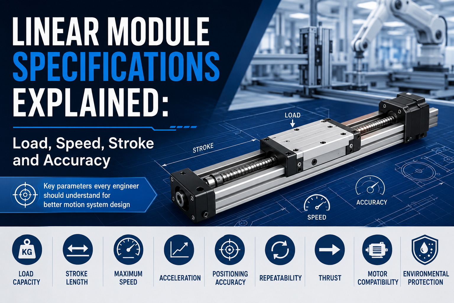
Why Understanding Linear Module Specifications Is Important
Every linear module specification directly influences machine performance, reliability, and operating cost. Selecting a module based only on one parameter, such as maximum speed or positioning accuracy, often results in poor system performance because all specifications interact with one another.
For example, increasing payload usually reduces maximum acceleration, while selecting a longer stroke may affect rigidity and positioning accuracy. Likewise, choosing a larger motor may increase thrust but also increases moving mass and power consumption.
Successful linear motion system design requires balancing multiple performance characteristics rather than maximizing a single specification.
Engineers typically evaluate the following technical parameters before selecting a linear module:
- Maximum load capacity
- Stroke length
- Maximum travel speed
- Acceleration and deceleration
- Positioning accuracy
- Repeatability
- Available thrust
- Motor compatibility
- Environmental protection level
The following sections explain each specification in detail and describe how it influences overall machine performance.
Overview of Major Linear Module Specifications
| Specification | What It Describes | Why It Matters |
|---|---|---|
| Load Capacity | Maximum allowable payload | Determines carrying capability |
| Stroke | Maximum travel distance | Defines working range |
| Maximum Speed | Highest operating velocity | Affects production efficiency |
| Acceleration | Rate of speed increase | Determines cycle time |
| Positioning Accuracy | Absolute positioning precision | Determines machining quality |
| Repeatability | Ability to return to same position | Ensures production consistency |
| Thrust | Linear driving force | Determines motion capability |
| Motor Compatibility | Supported motor types | Influences system integration |
| Environmental Protection | Dust and moisture resistance | Determines operating environment |
1. Load Capacity
Load capacity is one of the first specifications engineers consider when selecting a linear module. It represents the maximum payload that the module can move safely while maintaining its designed accuracy, speed, and service life.
Many people assume load capacity refers only to the weight placed on the carriage. In reality, engineers must consider the complete moving mass, including fixtures, tooling, workpieces, cables, pneumatic devices, and any additional accessories mounted on the moving platform.
Dynamic forces generated during acceleration and deceleration also contribute significantly to the effective load experienced by the module.
Factors Affecting Load Capacity
- Payload weight
- Center of gravity position
- Acceleration and deceleration
- Installation direction
- Overturning moments
- Guide rail size
- Drive mechanism
- Structural rigidity
Even if the payload remains unchanged, increasing acceleration may substantially increase the required driving force, making correct load calculation essential during system design.
Static Load vs Dynamic Load
| Load Type | Description |
|---|---|
| Static Load | Force applied while stationary |
| Dynamic Load | Force generated during motion |
Dynamic load usually determines the actual operating capability because industrial automation systems rarely remain stationary during production.
Selecting a linear module with adequate load capacity improves reliability, reduces component wear, and extends service life.
2. Stroke Length
Stroke refers to the maximum linear travel distance that the carriage can move along the module. It defines the available working range for the application and is one of the most visible specifications during equipment design.
Stroke length varies significantly depending on the drive mechanism and application requirements.Ball screw modulesgenerally provide short to medium strokes with excellent positioning precision, while timing belt and rack-and-pinion modules support much longer travel distances.
Typical stroke ranges include:
| Drive Type | Typical Stroke Range |
|---|---|
| Ball Screw Module | 50 mm – 1500 mm |
| Timing Belt Module | 100 mm – 6000 mm or longer |
| Rack and Pinion Module | Several meters to tens of meters |
| Linear Motor Module | Application dependent |
Choosing a stroke that is significantly longer than required may reduce structural rigidity, increase moving mass, and raise overall equipment cost. Conversely, selecting an insufficient stroke limits machine functionality and future expansion.
Whenever possible, engineers should include a reasonable safety margin while avoiding excessive overdesign.
3. Maximum Speed
Maximum speed refers to the highest linear travel velocity that a linear module can achieve under specified operating conditions. It is usually expressed in millimeters per second (mm/s) or meters per second (m/s) and is an important indicator when evaluating production efficiency.
In many automation applications, higher travel speed directly reduces machine cycle time and increases production throughput. However, maximum speed should never be considered independently. A module operating at its maximum speed must also maintain acceptable positioning accuracy, stability, and service life.
The achievable speed depends on multiple factors, including the drive mechanism, payload, stroke length, motor power, controller performance, and installation conditions.
Factors Affecting Maximum Speed
- Drive mechanism type
- Moving load
- Motor power and torque
- Stroke length
- Guide rail rigidity
- Acceleration and deceleration settings
- Mechanical vibration
- Control system performance
As the moving load increases, the maximum achievable speed generally decreases because the motor must produce more force to accelerate and decelerate the payload safely.
Likewise, very long travel distances may require lower operating speeds to minimize vibration, belt oscillation, or structural deflection.
Typical Maximum Speeds by Drive Type
| Drive Type | Typical Maximum Speed | Main Characteristic |
|---|---|---|
| Ball Screw Module | 300–1000 mm/s | High precision |
| Timing Belt Module | 1000–5000 mm/s | High speed and long stroke |
| Rack and Pinion Module | 1000–3000 mm/s | Heavy-duty long travel |
| Linear Motor Module | 3000 mm/s and above | Ultra-high dynamic performance |
Although high speed improves productivity, engineers should always evaluate speed together with payload, acceleration, and positioning accuracy to achieve the best overall system performance.
4. Acceleration
Acceleration describes how quickly a linear module can increase its speed from a stationary position. It is normally expressed in meters per second squared (m/s²) and has a significant impact on machine cycle time.
Many engineers focus only on maximum speed when evaluating equipment performance. In reality, acceleration often has a greater influence on productivity, especially in short-stroke applications where the carriage spends little time traveling at maximum velocity.
For example, in electronic assembly equipment performing hundreds of short positioning movements each minute, rapid acceleration and deceleration contribute more to cycle time reduction than increasing maximum speed alone.
Factors Influencing Acceleration
- Motor torque
- Moving mass
- Drive mechanism efficiency
- Structural rigidity
- Controller tuning
- Required positioning accuracy
Higher acceleration requires greater driving force. If the selected motor cannot provide sufficient torque, acceleration must be reduced to maintain stable operation.
Excessive acceleration may also generate vibration, increase mechanical wear, and shorten component life. Therefore, acceleration should always be optimized according to application requirements rather than simply maximizing its value.
Typical Industrial Acceleration Ranges
| Application | Typical Acceleration |
|---|---|
| General Automation | 1–5 m/s² |
| Packaging Equipment | 3–10 m/s² |
| Electronics Assembly | 5–20 m/s² |
| Linear Motor Systems | Up to 50 m/s² or higher |
Proper acceleration settings improve production efficiency while maintaining smooth motion and protecting mechanical components from unnecessary stress.
5. Positioning Accuracy
Positioning accuracy indicates how closely the actual stopping position matches the commanded target position. It is one of the most important specifications for applications involving machining, inspection, assembly, and precision manufacturing.
For example, if a positioning command requests the carriage to move to 500.000 mm and the actual position is 500.015 mm, the positioning error is 0.015 mm.
Positioning accuracy depends on the combined performance of the mechanical transmission system, guide rails, servo motor, encoder resolution, controller, and machine structure.
Factors Affecting Positioning Accuracy
- Ball screw lead accuracy
- Timing belt elasticity
- Linear guide precision
- Servo encoder resolution
- Mechanical rigidity
- Thermal expansion
- Installation quality
- Controller calibration
Different drive mechanisms provide different positioning capabilities.
| Drive Type | Typical Positioning Accuracy |
|---|---|
| Timing Belt Module | ±0.05 mm to ±0.20 mm |
| Ball Screw Module | ±0.01 mm to ±0.03 mm |
| Linear Motor Module | Micron-level accuracy |
Higher positioning accuracy is especially important in semiconductor manufacturing, CNC machining, laser processing, coordinate measuring machines, and automated optical inspection equipment.
However, extremely high positioning accuracy also increases equipment cost. Engineers should therefore select an accuracy level appropriate for the application rather than simply choosing the highest available specification.
6. Repeatability
Repeatability describes a linear module's ability to return to the same position repeatedly after performing identical motion commands. Unlike positioning accuracy, repeatability measures consistency rather than absolute position error.
For many automated production lines, repeatability is actually more important than positioning accuracy because manufacturing processes often require identical movements thousands of times each day.
As an example, a pick-and-place robot may repeatedly move between two fixed locations. Even if the absolute position contains a small offset, production quality remains stable provided the module consistently returns to the same position.
Positioning Accuracy vs Repeatability
| Specification | Meaning |
|---|---|
| Positioning Accuracy | Difference between commanded position and actual position |
| Repeatability | Ability to return to the same position repeatedly |
Because these two specifications describe different performance characteristics, they should never be confused during equipment selection.
Factors Influencing Repeatability
- Mechanical backlash
- Bearing quality
- Guide rail preload
- Servo control stability
- Structural rigidity
- Thermal stability
- Mechanical wear
Typical repeatability values include:
| Drive Type | Typical Repeatability |
|---|---|
| Timing Belt Module | ±0.05 mm |
| Ball Screw Module | ±0.01 mm |
| Precision Linear Motor Module | ±0.001 mm or better |
Excellent repeatability ensures stable product quality, consistent assembly accuracy, and reliable long-term operation in automated manufacturing systems.
For applications such as dispensing, electronic assembly, vision inspection, and automated testing, repeatability often becomes the primary performance indicator when selecting a linear module.
7. Thrust
Thrust is the linear driving force generated by a linear module to move, accelerate, and stop a load. It is usually expressed in Newtons (N) or kilonewtons (kN). Thrust directly determines whether a linear module can move a specific payload under the required operating conditions.
Many users mistakenly believe that thrust is determined only by the motor. In reality, available thrust is influenced by multiple factors, including motor torque, transmission efficiency, screw lead, belt characteristics, gear ratio, controller settings, and acceleration requirements.
Selecting a module with insufficient thrust may result in slow acceleration, unstable positioning, motor overload, or even failure to complete the required motion.
Factors Affecting Thrust
- Motor torque
- Drive mechanism efficiency
- Ball screw lead or pulley diameter
- Gear reduction ratio
- Moving load
- Acceleration and deceleration
- Friction within the motion system
During module selection, engineers should calculate the required thrust based on both static loads and dynamic forces generated during acceleration. A reasonable safety margin should also be included to ensure reliable long-term operation.
Typical Thrust Characteristics
| Drive Type | Typical Thrust Characteristic | Suitable Applications |
|---|---|---|
| Ball Screw Module | High thrust | Heavy load and precision positioning |
| Timing Belt Module | Medium thrust | High-speed material handling |
| Rack and Pinion Module | High thrust over long travel | Large automation systems |
| Linear Motor Module | Dynamic continuous thrust | Ultra-high-speed precision automation |
8. Motor Compatibility
Motor compatibility describes the ability of a linear module to integrate with different types of motors and motion control systems. Proper motor selection is essential for achieving the desired speed, acceleration, positioning accuracy, and overall machine performance.
Most industrial linear modules support standardized motor mounting interfaces, allowing users to install motors from various manufacturers with minimal mechanical modification.
Common Compatible Motor Types
- Servo motors
- Stepper motors
- Linear motors
- AC motors with reducers
Servo motors are widely used in applications requiring high speed, high acceleration, and closed-loop positioning. Stepper motors provide a cost-effective solution for light-duty automation where moderate accuracy and speed are acceptable.
When selecting a motor, engineers should evaluate:
- Rated torque
- Peak torque
- Rated speed
- Encoder resolution
- Inertia motor
- Drive voltage
- Communication protocol
- Controller compatibility
Proper matching between the motor and the linear module ensures stable operation, maximizes performance, and extends equipment service life.
9. Environmental Protection
Industrial environments vary significantly. Some applications operate in cleanrooms, while others are exposed to dust, moisture, cutting fluids, oil mist, or corrosive chemicals. Environmental protection is therefore an important specification that directly influences reliability and service life.
Manufacturers provide different protection options according to application requirements.
Common Protection Features
- Dust-proof covers
- Sealed guide rails
- Protective bellows
- Stainless steel components
- Anti-corrosion surface treatment
- Centralized lubrication systems
Applications in food processing, pharmaceuticals, semiconductor manufacturing, and medical equipment may require cleanroom-compatible designs with low particle generation.
Heavy industrial environments such as welding, machining, and mining may require higher protection against dust, coolant, metal chips, and vibration.
| Working Environment | Recommended Configuration |
|---|---|
| General Factory | Standard protection |
| Dusty Environment | Protective cover and sealed guide |
| Cleanroom | Low-particle cleanroom version |
| Corrosive Environment | Stainless steel and anti-corrosion treatment |
How to Read a Linear Module Specification Sheet
A specification sheet provides all the key technical parameters required for selecting a linear module. Rather than evaluating a single specification independently, engineers should consider the relationship between multiple parameters.
A typical specification sheet includes:
- Model number
- Drive mechanism
- Maximum load capacity
- Maximum stroke
- Maximum speed
- Maximum acceleration
- Positioning accuracy
- Repeatability
- Maximum thrust
- Motor mounting dimensions
- Module dimensions
- Lubrication requirements
- Operating temperature
- Environmental protection options
Before selecting a module, engineers should verify that every specification satisfies the application's actual operating requirements rather than focusing on only one or two performance indicators.
Common Mistakes When Selecting Linear Module Specifications
- Selecting a module based only on maximum load capacity.
- Ignoring acceleration during motor selection.
- Confusing positioning accuracy with repeatability.
- Choosing excessive stroke length without necessity.
- Selecting the highest speed instead of the most appropriate speed.
- Ignoring installation orientation and overturning moments.
- Overlooking environmental protection requirements.
- Failing to include an adequate safety factor.
Avoiding these common mistakes improves machine reliability, reduces operating costs, and helps achieve optimal motion performance throughout the equipment lifecycle.
Frequently Asked Questions
What are the most important specifications of a linear module?
The most important specifications include load capacity, stroke length, maximum speed, acceleration, positioning accuracy, repeatability, thrust, motor compatibility, and environmental protection.
What is the difference between positioning accuracy and repeatability?
Positioning accuracy measures how close the carriage stops to the commanded position, while repeatability measures the ability to return to the same position consistently over multiple cycles.
How do I choose the correct stroke length?
Select a stroke slightly longer than the required travel distance to provide a reasonable safety margin while avoiding unnecessary increases in module size and cost.
Why is acceleration important?
Acceleration has a major influence on machine cycle time, particularly in short-stroke applications where rapid starts and stops occur frequently.
Does a higher maximum speed always improve productivity?
Not necessarily. Productivity depends on the combined performance of speed, acceleration, payload, and motion profile. Excessively high speed may reduce stability and increase mechanical wear.
How is thrust determined?
Thrust depends on motor torque, transmission efficiency, drive mechanism, gear ratio, moving load, and acceleration requirements. Proper thrust calculation is essential for reliable operation.
Can the same linear module support different motors?
Yes. Most industrial linear modules provide standardized mounting interfaces that support various servo motors and stepper motors from different manufacturers.
Why is environmental protection important?
Appropriate protection against dust, moisture, chemicals, and contaminants extends service life, reduces maintenance, and improves long-term reliability.
Conclusion
Understanding linear module specifications is essential for selecting the right motion solution for any automation application. Parameters such as load capacity, stroke, maximum speed, acceleration, positioning accuracy, repeatability, thrust, motor compatibility, and environmental protection are closely related and should always be evaluated together rather than individually.
A properly selected linear module not only delivers the required motion performance but also improves machine reliability, simplifies integration, reduces maintenance, and lowers the total cost of ownership throughout the equipment lifecycle.
Whether designing precision semiconductor equipment, high-speed packaging machinery, CNC systems, industrial robots, or automated production lines, a thorough understanding of linear module specifications enables engineers to optimize equipment performance and build efficient, reliable, and future-ready automation systems.
