 English

A linear module is an integrated motion system designed to convert rotary or electromagnetic power into smooth, accurate, and repeatable linear movement. Although a linear module may appear to be a single mechanical assembly, it is actually composed of multiple precision-engineered components that work together to deliver high positioning accuracy, high speed, long service life, and reliable automation performance.
Every component inside a linear module has a specific responsibility. The linear guide supports and constrains movement, the drive mechanism generates motion, bearings reduce friction, the motor provides power, sensors monitor position, and structural elements maintain rigidity. When these components are properly matched, the result is an efficient linear motion system capable of operating continuously in industrial environments.
Whether the application involves CNC machinery, semiconductor manufacturing, packaging equipment, robotics, medical devices, or automated production lines, understanding each component helps engineers select the right module, improve machine reliability, simplify maintenance, and optimize overall system performance.
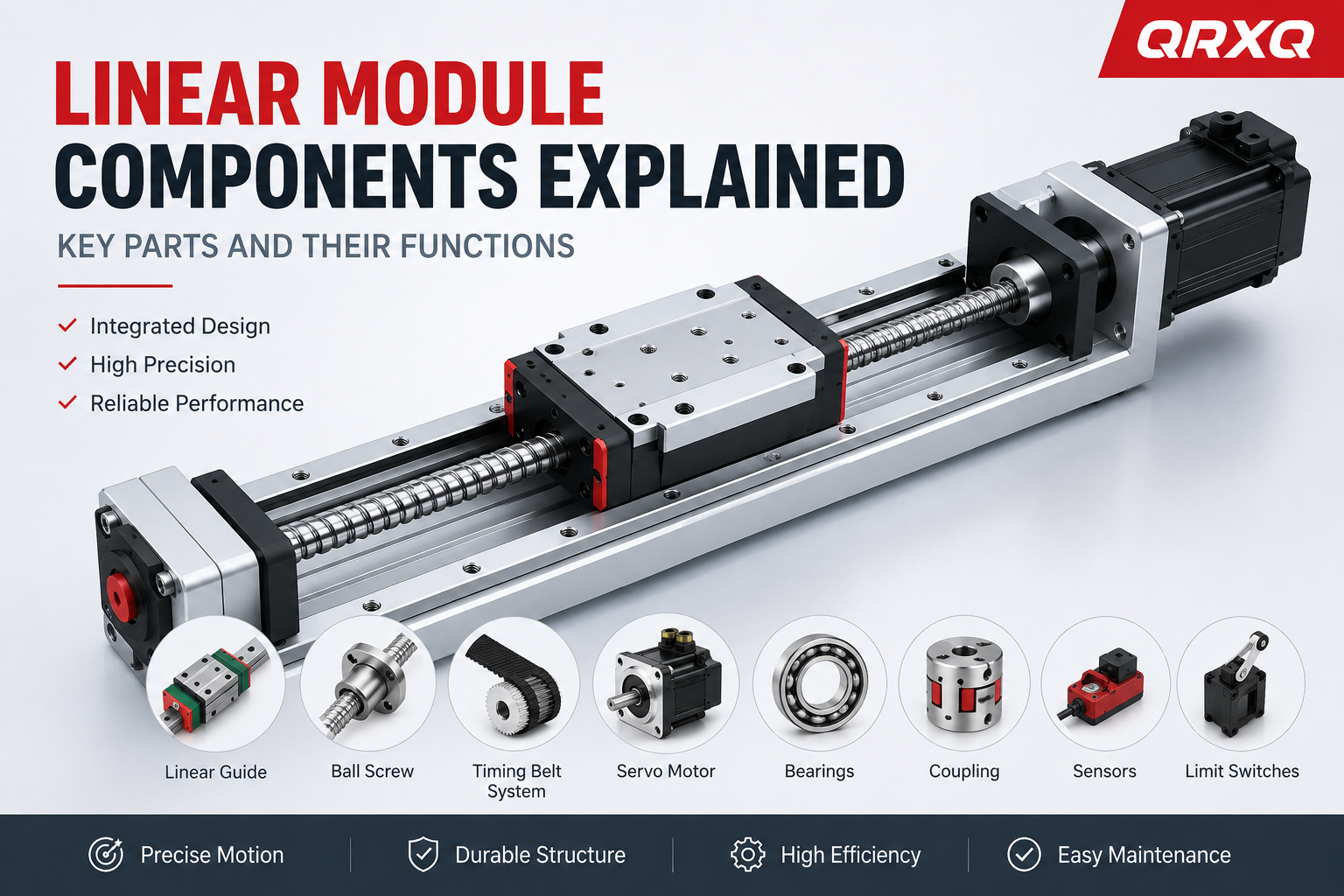
Table of Contents
- What Are Linear Module Components?
- Why Every Component Matters
- Overview of Linear Module Architecture
- Main Categories of Components
- Linear Guide System
- Drive Mechanisms
- Ball Screw Assemblies
- Timing Belt Systems
- Linear Motors
- Bearings and Support Units
- Couplings
- Servo Motors
- Sensors and Limit Switches
- How Components Work Together
- Selecting the Right Components
- Maintenance Recommendations
- Frequently Asked Questions
What Are Linear Module Components?
Linear module components are the mechanical, electrical, and control elements that collectively enable controlled linear motion. Instead of relying on a single moving part, a complete linear module integrates multiple subsystems into one compact assembly. Each subsystem contributes a specific function that influences positioning accuracy, load capacity, operating speed, repeatability, and service life.
Unlike traditional machine designs where guides, screws, motors, and sensors are installed separately, modernlinear modulescombine these elements into a standardized platform. This integrated approach simplifies installation, reduces alignment errors, shortens engineering time, and improves system consistency.
The exact configuration varies depending on the drive technology.Ball screw linear modulesprioritize positioning precision and thrust force,timing belt modulesemphasize long travel and high speed, while linear motor modules deliver exceptional acceleration and ultra-high precision without mechanical transmission components.
Why Every Component Matters
The overall performance of a linear module depends not on a single high-quality part but on the interaction between all components. Even if a module uses premium guide rails, insufficient bearing support or an improperly selected motor can reduce positioning accuracy and shorten service life.
Each component influences multiple aspects of machine performance:
- Motion accuracy and repeatability
- Maximum operating speed
- Acceleration capability
- Load carrying capacity
- Mechanical rigidity
- Vibration resistance
- Noise level
- Maintenance interval
- Operational reliability
- Total equipment lifespan
Because these factors are interconnected, component selection should always be considered as a complete engineering system rather than individual parts purchased independently.
Overview of Linear Module Architecture
A complete linear module generally consists of four integrated subsystems: the structural system, motion guidance system, power transmission system, and control system. Together they create a highly coordinated motion platform capable of precise and repeatable linear travel.
The structural frame provides rigidity and supports all internal components. Mounted on the frame are precision linear guide rails that ensure smooth movement while preventing unwanted rotation or deflection.
Motion is generated by the drive mechanism. Depending on the module design, this may be a ball screw assembly, timing belt transmission, or direct-drive linear motor. The drive converts motor output into controlled linear displacement.
A servo motor or stepper motor supplies rotational power for mechanical transmission systems, while a direct-drive linear motor generates force without intermediate mechanical components.
Sensors, encoders, and limit switches continuously monitor position and operating status, enabling closed-loop motion control and improving positioning accuracy.
Main Categories of Linear Module Components
Although manufacturers may use different structural designs, most industrial linear modules contain the following major component categories.
| Component Category | Primary Function | Typical Examples |
|---|---|---|
| Guide System | Supports accurate linear motion | Linear guides, guide rails, sliders |
| Drive System | Generates linear movement | Ball screw, timing belt, linear motor |
| Power System | Provides driving force | Servo motor, stepper motor |
| Transmission Parts | Transfers torque efficiently | Couplings, pulleys, shafts |
| Support Components | Reduce friction and support loads | Bearings, bearing blocks |
| Control Components | Monitor position and operation | Sensors, encoders, limit switches |
| Structural Components | Provide rigidity and protection | Aluminum base, covers, mounting plates |
Every category contributes differently to system performance. Mechanical components determine stiffness and load capacity, transmission components influence efficiency and backlash, while electronic components improve positioning precision and operational safety.
How the Components Work Together
A linear module operates as a coordinated mechanical system rather than a collection of independent parts. When amotion controllerissues a movement command, the servo motor generates rotational torque. This torque is transmitted through a coupling to the drive mechanism, which may be a ball screw, timing belt, or linear motor system.
The drive mechanism converts motor output into linear displacement, moving the carriage along precision guide rails. Bearings minimize friction during travel, while sensors and encoders continuously report position feedback to the controller. If the carriage reaches its travel limit, limit switches provide protective signals that prevent overtravel and equipment damage.
Because every component interacts with the others, improving one part while neglecting another rarely produces significant performance gains. A balanced design ensures accuracy, speed, rigidity, reliability, and long-term stability.
Understanding Component Integration
One of the greatest advantages of modern linear modules is component integration. Instead of purchasing guide rails, bearings, motors, screws, sensors, and structural frames separately, manufacturers integrate these elements into a factory-aligned assembly. This approach reduces installation time, minimizes alignment errors, and improves repeatability across multiple machines.
Integrated designs also simplify maintenance because replacement components are engineered to work together within defined tolerances. For automation equipment builders, this reduces engineering complexity while improving production efficiency.
In the following sections, each major component—including linear guides, ball screws, timing belts, linear motors, bearings, couplings, servo motors, sensors, and limit switches—will be explained in detail, including its structure, working principle, advantages, limitations, and role within a complete linear module.
Linear Guide System
The linear guide system is one of the most critical components of a linear module. It supports the moving carriage and ensures that motion follows a precise straight-line path with minimal friction. Without a high-quality guide system, even the most advanced drive mechanism cannot achieve accurate positioning or smooth operation.
Modern linear guides are designed to carry loads in multiple directions while maintaining excellent rigidity and repeatability. They are manufactured with precision-ground raceways and rolling elements that significantly reduce friction compared with traditional sliding guides. This enables higher speeds, greater efficiency, and longer service life in demanding industrial applications.
What Is a Linear Guide?
A linear guide is a precision motion component that allows a carriage or slider to move accurately along a fixed rail. It constrains motion to one linear axis while resisting forces and moments generated during machine operation.
In a linear module, the guide system works together with the drive mechanism. While the ball screw, timing belt, or linear motor generates motion, the guide rail ensures that the carriage follows a straight path without unwanted rotation, vibration, or deviation.
The performance of the guide system directly affects positioning accuracy, repeatability, load capacity, and overall machine stability.
Main Components of a Linear Guide
Although designs vary among manufacturers, a typical linear guide assembly consists of the following components:
| Component | Function |
|---|---|
| Guide Rail | Provides the precision track for linear movement. |
| Carriage (Slider) | Moves along the guide rail while supporting the load. |
| Rolling Elements | Balls or rollers that reduce friction. |
| Raceways | Precision-ground contact surfaces for rolling elements. |
| End Caps | Guide rolling elements through the recirculation path. |
| Lubrication System | Supplies grease or oil to reduce wear. |
| Seals | Prevent dust and contaminants from entering the guide. |
How a Linear Guide Works
The guide rail is securely mounted to the module base, while the carriage travels along the rail using recirculating balls or rollers. As the carriage moves, the rolling elements circulate continuously through internal return channels, allowing smooth movement with extremely low rolling resistance.
Unlike sliding contact surfaces that generate significant friction, rolling contact greatly reduces wear and energy loss. This design enables linear modules to achieve high positioning accuracy while maintaining excellent efficiency over millions of operating cycles.
Because the rolling elements remain under preload, the guide system also minimizes backlash and increases rigidity, making it suitable for precision automation equipment.
Types of Linear Guides
Different guide designs are available to satisfy various application requirements.
| Guide Type | Characteristics | Typical Applications |
|---|---|---|
| Ball Linear Guide | Low friction, high speed, economical | General automation equipment |
| Roller Linear Guide | Higher rigidity and load capacity | Heavy-duty machinery |
| Miniature Linear Guide | Compact size and lightweight | Medical devices and electronics |
| Wide Rail Guide | Improved moment resistance | Large gantry systems |
| Cross Roller Guide | Ultra-high precision | Inspection and semiconductor equipment |
Advantages of Linear Guides
- High positioning accuracy
- Excellent repeatability
- Low rolling friction
- High operating speed
- Long service life
- High rigidity under load
- Reduced maintenance requirements
- Smooth and quiet operation
- Suitable for continuous industrial operation
Limitations of Linear Guides
Although linear guides provide outstanding performance, they also have several limitations that engineers should consider during machine design.
- Sensitive to dust and contamination without proper sealing.
- Require periodic lubrication.
- Installation accuracy directly affects performance.
- Misalignment may reduce service life.
- Heavy shock loads can damage rolling elements.
Applications of Linear Guides
Linear guides are widely used in industrial automation because they provide precise, repeatable motion with minimal maintenance.
- CNC machining centers
- Industrial robots
- Pick-and-place systems
- Packaging machinery
- Laser cutting equipment
- Medical automation
- Semiconductor manufacturing
- Inspection systems
- Battery production lines
- Electronic assembly equipment
Carriage (Slider)
The carriage, also known as the slider or guide block, is the moving component that travels along the guide rail. It supports the payload and transfers driving force from the transmission system to the moving load.
In a linear module, the carriage serves as the mounting platform for workpieces, tooling, robotic end effectors, or machine components. Its rigidity and precision directly influence positioning accuracy and system stability.
Structure of a Carriage
A standard carriage contains several precision components working together to ensure smooth movement.
| Part | Purpose |
|---|---|
| Body | Main structural support. |
| Ball or Roller Circuits | Enable rolling motion. |
| End Caps | Guide recirculating elements. |
| Lubrication Ports | Allow grease replenishment. |
| Dust Seals | Protect internal components. |
| Mounting Holes | Connect external equipment. |
Functions of the Carriage
- Supports moving loads.
- Transfers driving force.
- Maintains motion accuracy.
- Resists overturning moments.
- Provides mounting interfaces.
- Absorbs operational forces.
Factors Affecting Carriage Performance
Several design parameters determine the overall performance of the carriage.
- Preload level
- Number of rolling elements
- Contact angle
- Material quality
- Heat treatment
- Lubrication quality
- Manufacturing precision
Higher preload generally increases rigidity but also raises friction. Engineers must balance stiffness and operating efficiency according to application requirements.
Bearings
Bearings are fundamental support components throughout a linear module. They reduce friction, support rotating shafts, maintain alignment, and improve transmission efficiency.
Although users often associate bearings only with motors, bearings are also found in screw support units, pulley assemblies, coupling systems, and other rotating mechanisms inside a linear module.
Functions of Bearings
- Support rotating shafts.
- Reduce friction.
- Maintain rotational accuracy.
- Carry radial loads.
- Carry axial loads.
- Improve transmission efficiency.
- Extend equipment life.
Common Bearing Types
| Bearing Type | Main Feature | Typical Location |
|---|---|---|
| Deep Groove Ball Bearing | High-speed capability | Motor shafts |
| Angular Contact Bearing | Supports combined loads | Ball screw support units |
| Tapered Roller Bearing | High load capacity | Heavy machinery |
| Needle Bearing | Compact radial design | Special transmission systems |
| Thrust Bearing | Supports axial loads | Screw assemblies |
Importance of Bearing Quality
High-quality bearings improve rotational accuracy, reduce vibration, minimize heat generation, and extend the service life of the entire linear module. Precision-grade bearings are particularly important in applications requiring micron-level positioning accuracy.
Bearing preload, lubrication, sealing quality, and installation accuracy all influence operating performance. Improper bearing installation may introduce excessive vibration, increased friction, premature wear, and positioning errors.
Maintenance Recommendations for Guide Systems and Bearings
- Inspect guide rails for contamination regularly.
- Lubricate according to the manufacturer's maintenance schedule.
- Avoid impact loads during installation.
- Monitor abnormal vibration and operating noise.
- Replace damaged seals promptly.
- Keep guide rails clean and free from metal chips.
- Verify mounting bolt torque periodically.
- Check carriage smoothness during preventive maintenance.
Proper maintenance significantly extends the service life of both the guide system and its bearings while maintaining consistent positioning accuracy throughout the operational lifetime of the linear module.
Drive System
The drive system is the core power transmission mechanism of a linear module. Its primary function is to convert rotational or electromagnetic energy into controlled linear motion. While the guide system determines how accurately the carriage moves, the drive system determines how the motion is generated, including its speed, thrust, acceleration, travel distance, and transmission efficiency.
Modern linear modules typically employ one of three major drive technologies: ball screw drives, timing belt drives, or direct-drive linear motors. Each technology offers distinct advantages and is optimized for different industrial applications.
Selecting the appropriate drive system requires evaluating multiple factors, including positioning accuracy, travel length, payload, maximum speed, acceleration, operating environment, maintenance requirements, and total cost of ownership.
Ball Screw
The ball screw is one of the most widely used transmission components in precision linear modules. It converts the rotary motion of a servo or stepper motor into highly accurate linear motion through the rolling movement of steel balls between the screw shaft and the ball nut.
Compared with conventional lead screws, ball screws use rolling contact instead of sliding friction, resulting in significantly higher transmission efficiency, lower wear, reduced heat generation, and longer service life.
Main Components of a Ball Screw Assembly
| Component | Function |
|---|---|
| Ball Screw Shaft | Provides the precision helical raceway. |
| Ball Nut | Travels along the screw during rotation. |
| Steel Balls | Transmit force while minimizing friction. |
| Ball Return System | Recirculates balls continuously. |
| Support Bearings | Maintain shaft alignment and rigidity. |
| End Supports | Secure the screw within the module. |
How a Ball Screw Works
When the motor rotates the screw shaft, the ball nut moves linearly along the threaded raceway. Precision steel balls circulate continuously between the screw and nut, dramatically reducing friction while transferring axial force efficiently.
Because rolling friction is much lower than sliding friction, transmission efficiency commonly exceeds 90%. This allows the system to achieve excellent positioning accuracy with relatively low power consumption.
Advantages of Ball Screws
- Excellent positioning accuracy.
- High repeatability.
- High transmission efficiency.
- Low friction and reduced wear.
- High thrust capability.
- Suitable for precision servo control.
- Long operating life with proper lubrication.
- Minimal backlash when preloaded.
Limitations of Ball Screws
- Maximum travel is relatively limited.
- Critical speed limits very long screws.
- Requires regular lubrication.
- Higher manufacturing cost than belt systems.
- Sensitive to contamination.
Typical Applications
- CNC machining centers
- Precision assembly equipment
- Medical automation
- Semiconductor manufacturing
- Inspection systems
- Laser processing machines
- High-precision dispensing equipment
Timing Belt
Timing belt drives are commonly used in linear modules requiring high travel speeds and long stroke lengths. Instead of transmitting force through threaded mechanical contact, a reinforced timing belt transfers motion between pulleys, allowing the carriage to move rapidly over long distances.
Because the belt is lightweight and has relatively low inertia, timing belt modules can achieve higher acceleration and faster travel than comparable ball screw systems.
Main Components of a Timing Belt Drive
| Component | Purpose |
|---|---|
| Timing Belt | Transfers driving force. |
| Drive Pulley | Powered by the motor. |
| Idler Pulley | Maintains belt routing. |
| Belt Tensioning System | Maintains proper belt tension. |
| Motor Mount | Supports the driving motor. |
| Carriage Connection | Links the belt to the moving slider. |
How a Timing Belt Drive Works
The motor rotates the drive pulley, causing the toothed timing belt to move synchronously. Since the carriage is mechanically attached to the belt, it travels along the guide rail at the same speed as the belt.
The positive engagement between the belt teeth and pulley grooves eliminates slippage under normal operating conditions, ensuring reliable motion transmission.
Advantages of Timing Belt Systems
- High operating speed.
- Long travel capability.
- Light moving mass.
- High acceleration.
- Quiet operation.
- Cost-effective for large machines.
- Suitable for continuous production lines.
Limitations of Timing Belt Systems
- Lower positioning accuracy than ball screws.
- Belt stretch may occur over time.
- Lower thrust capability.
- Requires periodic tension adjustment.
Typical Applications
- Packaging equipment
- Material handling systems
- Warehouse automation
- Cartesian robots
- Gantry robots
- Pick-and-place equipment
- Large-format printing machinery
Linear Motor
Unlike ball screw and timing belt systems, a linear motor generates linear motion directly without any intermediate mechanical transmission components. It can be regarded as a conventional rotary servo motor that has been "unrolled" into a straight line.
The elimination of mechanical transmission results in virtually zero backlash, extremely high acceleration, and exceptional positioning accuracy.
Main Components of a Linear Motor System
| Component | Function |
|---|---|
| Primary Coil | Generates electromagnetic force. |
| Magnet Track | Provides the magnetic field. |
| Linear Encoder | Measures position accurately. |
| Servo Drive | Controls motor current. |
| Cooling System | Dissipates generated heat. |
Advantages of Linear Motors
- No mechanical backlash.
- Ultra-high positioning accuracy.
- Extremely high acceleration.
- High operating speed.
- Minimal mechanical wear.
- Excellent dynamic response.
- Reduced maintenance requirements.
Limitations of Linear Motors
- Higher initial investment.
- Greater controller complexity.
- Higher heat generation.
- Requires high-resolution feedback systems.
Typical Applications
- Semiconductor equipment
- Precision inspection systems
- High-speed electronics manufacturing
- Optical positioning equipment
- Scientific research instruments
- Ultra-precision automation systems
Coupling
The coupling is a mechanical transmission component that connects the motor shaft to the drive mechanism, typically a ball screw or pulley. Although relatively small in size, it plays a vital role in maintaining transmission accuracy, compensating for shaft misalignment, and protecting drivetrain components from excessive stress.
Functions of a Coupling
- Transmit motor torque efficiently.
- Compensate for minor shaft misalignment.
- Reduce vibration.
- Absorb shock loads.
- Protect bearings and screws.
- Maintain rotational accuracy.
Common Coupling Types
| Coupling Type | Main Characteristics | Typical Applications |
|---|---|---|
| Flexible Coupling | Compensates for slight misalignment. | General automation equipment |
| Bellows Coupling | High torsional rigidity and zero backlash. | Precision servo systems |
| Jaw Coupling | Shock absorption and vibration damping. | Medium-duty machinery |
| Disc Coupling | High precision and high-speed operation. | High-performance motion systems |
Selecting the Appropriate Drive Mechanism
No single drive technology is ideal for every application. Engineers should evaluate performance requirements before selecting a linear module.
| Requirement | Recommended Drive |
|---|---|
| Highest positioning accuracy | Ball Screw or Linear Motor |
| Longest travel distance | Timing Belt |
| Highest operating speed | Linear Motor |
| Highest thrust force | Ball Screw |
| Best cost-performance ratio | Timing Belt |
| Ultra-clean applications | Linear Motor |
Understanding the characteristics of each drive mechanism enables engineers to select a linear module that delivers the optimal balance of precision, speed, reliability, and lifecycle cost for their specific automation application.
Servo Motor
The servo motor is the primary power source for most precision linear modules. It provides controlled rotational motion that is converted into linear movement through a ball screw or timing belt transmission. Unlike conventional motors that simply rotate at a fixed speed, servo motors continuously receive feedback from the controller and automatically adjust their position, speed, and torque to achieve highly accurate motion.
Because of their excellent dynamic response and closed-loop control capability, servo motors are widely used in industrial automation systems requiring high precision, fast acceleration, and reliable repeatability.
How a Servo Motor Works
A servo system consists of three major elements: the servo motor, the servo drive, and a feedback device such as an encoder. During operation, the motion controller sends movement commands to the servo drive. The drive regulates the electrical current supplied to the motor while continuously comparing the commanded position with actual feedback from the encoder.
If any deviation occurs, the controller immediately compensates for the error, ensuring that the carriage reaches the desired position accurately and efficiently.
Main Components of a Servo System
| Component | Function |
|---|---|
| Servo Motor | Generates rotational power. |
| Servo Drive | Controls motor current, speed, and position. |
| Encoder | Provides real-time position feedback. |
| Power Cable | Supplies electrical power. |
| Feedback Cable | Transmits encoder signals. |
Advantages of Servo Motors
- High positioning accuracy.
- Closed-loop motion control.
- Excellent repeatability.
- Fast acceleration and deceleration.
- High torque over a wide speed range.
- Stable operation under varying loads.
- Energy-efficient operation.
Typical Applications
- CNC machining centers
- Industrial robots
- Precision assembly systems
- Packaging equipment
- Medical automation
- Semiconductor manufacturing
- Laser processing machines
Stepper Motor
Stepper motors are another common drive option for linear modules, particularly in applications where moderate positioning accuracy and cost efficiency are more important than maximum speed or dynamic performance.
Unlike servo motors, stepper motors rotate in discrete angular increments called steps. The controller determines the motor position by counting these steps rather than relying on continuous feedback.
Although many stepper systems operate without feedback, modern closed-loop stepper motors combine traditional stepping technology with encoder feedback to improve positioning accuracy and reduce the risk of missed steps.
Advantages of Stepper Motors
- Simple control architecture.
- Lower initial cost.
- Good low-speed torque.
- Suitable for light-duty automation.
- Easy integration.
Limitations of Stepper Motors
- Lower maximum speed than servo motors.
- Reduced efficiency at high speeds.
- Potential for missed steps in open-loop systems.
- Lower dynamic response.
Servo Motor vs. Stepper Motor
| Feature | Servo Motor | Stepper Motor |
|---|---|---|
| Position Feedback | Closed-loop | Usually open-loop |
| Accuracy | Very high | Moderate |
| Maximum Speed | High | Moderate |
| Dynamic Performance | Excellent | Average |
| Cost | Higher | Lower |
| Typical Applications | Precision automation | General automation |
Sensors
Sensors are essential monitoring devices within a linear module. They detect operating conditions and provide real-time information to the motion controller, enabling safe, reliable, and accurate system operation.
Depending on the application, sensors may monitor position, proximity, speed, temperature, vibration, or other operating parameters. Their data allows the controller to coordinate movement, prevent collisions, and improve automation efficiency.
Common Sensor Types
| Sensor Type | Primary Function |
|---|---|
| Inductive Sensor | Detects metal objects. |
| Photoelectric Sensor | Detects objects using light. |
| Magnetic Sensor | Detects magnetic fields. |
| Hall Effect Sensor | Detects magnet position. |
| Temperature Sensor | Monitors motor or bearing temperature. |
| Vibration Sensor | Monitors machine condition. |
Benefits of Sensors
- Improve positioning reliability.
- Increase operational safety.
- Support predictive maintenance.
- Reduce machine downtime.
- Enhance production efficiency.
- Enable intelligent automation.
Limit Switches
Limit switches are protective devices installed near the ends of a linear module's travel range. Their primary purpose is to prevent the carriage from moving beyond its allowable stroke, thereby protecting both the module and connected equipment from mechanical damage.
When the carriage reaches a predefined position, the limit switch sends a signal to the controller. The controller then stops or reverses the motor according to the programmed operating sequence.
Types of Limit Switches
| Type | Characteristics |
|---|---|
| Mechanical Limit Switch | Physical contact activation. |
| Inductive Limit Sensor | Non-contact metal detection. |
| Magnetic Limit Sensor | Activated by magnetic field. |
| Optical Limit Sensor | Uses light interruption. |
Functions of Limit Switches
- Prevent overtravel.
- Protect mechanical components.
- Support automatic homing.
- Provide emergency stop signals.
- Improve operational safety.
Linear Encoder
A linear encoder is a precision feedback device used to measure the actual position of the moving carriage. Unlike rotary encoders that monitor motor shaft rotation, linear encoders directly measure linear displacement, eliminating transmission errors caused by screw pitch variation, belt stretch, or mechanical backlash.
High-end linear modules often integrate optical or magnetic linear encoders to achieve micron-level positioning accuracy required in semiconductor manufacturing, precision inspection, and scientific instrumentation.
Advantages of Linear Encoders
- Direct position measurement.
- Higher positioning accuracy.
- Compensation for transmission errors.
- Excellent repeatability.
- Improved closed-loop control.
Cable Management System
Although often overlooked, the cable management system is an important supporting component within a linear module. It organizes and protects power cables, encoder cables, pneumatic hoses, and communication lines while allowing continuous movement without excessive bending or wear.
Proper cable management improves system reliability, reduces maintenance costs, and prevents unexpected cable failures caused by repeated motion.
Common Cable Management Components
- Energy chains (drag chains)
- Cable carriers
- Flexible cable clamps
- Protective cable sleeves
- Cable support brackets
How Electrical Components Work Together
The electrical and control components of a linear module operate as an integrated motion control system. The motion controller generates movement commands based on the automation program. The servo drive interprets these commands and regulates the motor accordingly. The motor drives the transmission mechanism, while sensors and encoders continuously monitor operating conditions and provide feedback to the controller.
If the carriage approaches its travel limit, the limit switch immediately sends a protection signal. The controller responds by slowing, stopping, or reversing motion, ensuring safe operation and preventing equipment damage.
Together, the servo motor, stepper motor, sensors, encoders, limit switches, and cable management system provide the intelligence, precision, and reliability required for modern industrial automation.
How to Select the Right Linear Module Components
Selecting the appropriate components for a linear module is one of the most important engineering decisions during machine design. A well-balanced configuration improves positioning accuracy, operating efficiency, reliability, and equipment lifespan, while an unsuitable combination may lead to excessive wear, poor motion quality, unnecessary maintenance, or increased operating costs.
Rather than selecting individual parts independently, engineers should evaluate the entire motion system based on application requirements. Factors such as payload, travel distance, speed, acceleration, precision, operating environment, and maintenance expectations all influence component selection.
Key Selection Factors
| Selection Factor | Engineering Considerations |
|---|---|
| Load Capacity | Consider both payload and dynamic loads generated during acceleration and deceleration. |
| Stroke Length | Long strokes generally favor timing belt drives, while short and medium strokes often benefit from ball screws. |
| Positioning Accuracy | High-precision applications require ball screws or linear motors combined with precision guides. |
| Maximum Speed | Evaluate continuous operating speed as well as acceleration requirements. |
| Operating Environment | Consider dust, humidity, chemicals, temperature, and cleanroom requirements. |
| Duty Cycle | High-frequency production requires components designed for continuous operation. |
| Maintenance Requirements | Choose components with suitable lubrication intervals and service life. |
| Budget | Balance initial investment with lifecycle operating costs. |
Recommended Component Combinations
| Application | Recommended Configuration |
|---|---|
| High-Precision Positioning | Ball screw + Servo motor + Precision linear guide + Linear encoder |
| Long Stroke Automation | Timing belt + Servo motor + Ball linear guide |
| High-Speed Motion | Linear motor + Optical encoder + Roller guide |
| Heavy Load Handling | Large ball screw + Roller guide + High-torque servo motor |
| Cost-Effective Automation | Timing belt + Stepper motor + Standard linear guide |
| Cleanroom Equipment | Linear motor + Sealed guide + Non-contact sensors |
Common Component Failures and Troubleshooting
Even high-quality linear modules require periodic inspection. Continuous operation, contamination, insufficient lubrication, improper installation, or excessive loading can gradually reduce system performance. Early identification of abnormal conditions helps prevent costly downtime and extends equipment life.
| Symptom | Possible Cause | Recommended Solution |
|---|---|---|
| Abnormal vibration | Loose mounting, worn bearings, or damaged guide rails | Inspect mounting bolts, bearings, and guide system. |
| Reduced positioning accuracy | Backlash, encoder errors, or worn transmission components | Check preload, encoder calibration, and transmission wear. |
| Excessive operating noise | Insufficient lubrication or contamination | Clean and relubricate moving components. |
| Motor overheating | Overload, poor ventilation, or incorrect tuning | Reduce load and verify servo parameters. |
| Irregular movement | Sensor failure or electrical interference | Inspect sensors, wiring, and controller signals. |
| Belt slipping | Insufficient belt tension or pulley wear | Adjust belt tension or replace worn components. |
Maintenance Best Practices
Preventive maintenance is essential for maintaining the long-term performance of a linear module. A scheduled maintenance program reduces unexpected failures, improves operational reliability, and lowers total ownership costs.
Routine Maintenance Checklist
- Clean guide rails and exposed moving components regularly.
- Lubricate guide systems and ball screws according to the manufacturer's recommendations.
- Inspect belts for wear, cracking, or loss of tension.
- Check bearing condition for abnormal noise or vibration.
- Verify mounting bolt torque periodically.
- Inspect sensors and limit switches for proper operation.
- Monitor servo motor temperature during continuous operation.
- Check encoder feedback for positioning consistency.
- Inspect cable carriers and moving cables for damage.
- Replace worn seals before contamination enters the guide system.
Maintenance Frequency
| Maintenance Item | Suggested Interval |
|---|---|
| Visual inspection | Daily |
| Cleaning | Weekly |
| Lubrication | Monthly or according to operating hours |
| Fastener inspection | Quarterly |
| Complete system inspection | Annually |
Frequently Asked Questions
What are the main components of a linear module?
A complete linear module typically consists of a structural frame, linear guide rails, carriage, drive mechanism (ball screw, timing belt, or linear motor), motor, bearings, coupling, sensors, limit switches, encoder, and cable management system.
Which drive mechanism provides the highest positioning accuracy?
Ball screw drives and direct-drive linear motors generally provide the highest positioning accuracy. Linear motors eliminate mechanical transmission errors, while precision ball screws offer excellent repeatability with high thrust capacity.
When should I choose a timing belt instead of a ball screw?
Timing belt systems are recommended for applications requiring long travel distances, high operating speeds, and cost-effective automation. Ball screws are preferred when positioning accuracy and thrust are the primary requirements.
Why are linear guides important?
Linear guides maintain straight-line motion, reduce friction, support external loads, and ensure repeatable positioning. They are essential for achieving stable and accurate linear movement.
What is the purpose of a coupling?
A coupling connects the motor shaft to the drive mechanism while compensating for minor shaft misalignment, reducing vibration, and transmitting torque efficiently.
Do all linear modules require servo motors?
No. Many economical systems use stepper motors. However, servo motors are generally preferred for applications requiring high speed, high precision, and closed-loop motion control.
How often should a linear module be lubricated?
Lubrication intervals depend on operating conditions, travel distance, load, and environmental factors. Manufacturers typically provide recommended maintenance schedules based on operating hours or travel distance.
Can damaged guide rails affect positioning accuracy?
Yes. Worn or damaged guide rails increase friction, reduce rigidity, and introduce positioning errors, negatively affecting overall machine performance.
Which components require the most maintenance?
Guide rails, ball screws, bearings, timing belts, and lubrication systems typically require the most routine maintenance because they experience continuous mechanical movement.
How can component life be extended?
Proper installation, regular lubrication, contamination control, correct load selection, and preventive maintenance significantly increase the service life of linear module components.
Conclusion
A linear module is far more than a simple actuator. It is a highly integrated motion platform composed of precision mechanical, electrical, and control components that work together to deliver accurate, efficient, and reliable linear motion.
From the guide system and drive mechanism to the servo motor, bearings, sensors, limit switches, and encoder, every component plays a specific role in determining system performance. Careful component selection, correct installation, and regular maintenance are essential for achieving long service life, stable operation, and maximum productivity.
Whether designing a compact automation device, a high-speed packaging machine, a CNC production system, or a precision semiconductor platform, understanding the functions and interactions of each linear module component enables engineers to build more reliable and efficient motion systems that meet the demands of modern industrial automation.
