 English

linear module troubleshooting: should begin with a reproducible symptom, operating conditions and measured evidence. Replacing components before separating mechanical, electrical and control causes can hide the fault and increase downtime.
Alinear modulecombines a drive mechanism, a load-bearing guide, a carriage and motion control. The drive creates thrust; the guide constrains unwanted degrees of freedom; the controller commands the motion and evaluates feedback or limit signals. In the Troubleshooting scope, linear module troubleshooting must connect catalog capability with the actual load, stroke, speed, accuracy, environment and acceptance conditions.
The scope here connects Positioning Errors, Excessive Noise, Vibration, Reduced Accuracy with practical selection, installation, verification or maintenance decisions.
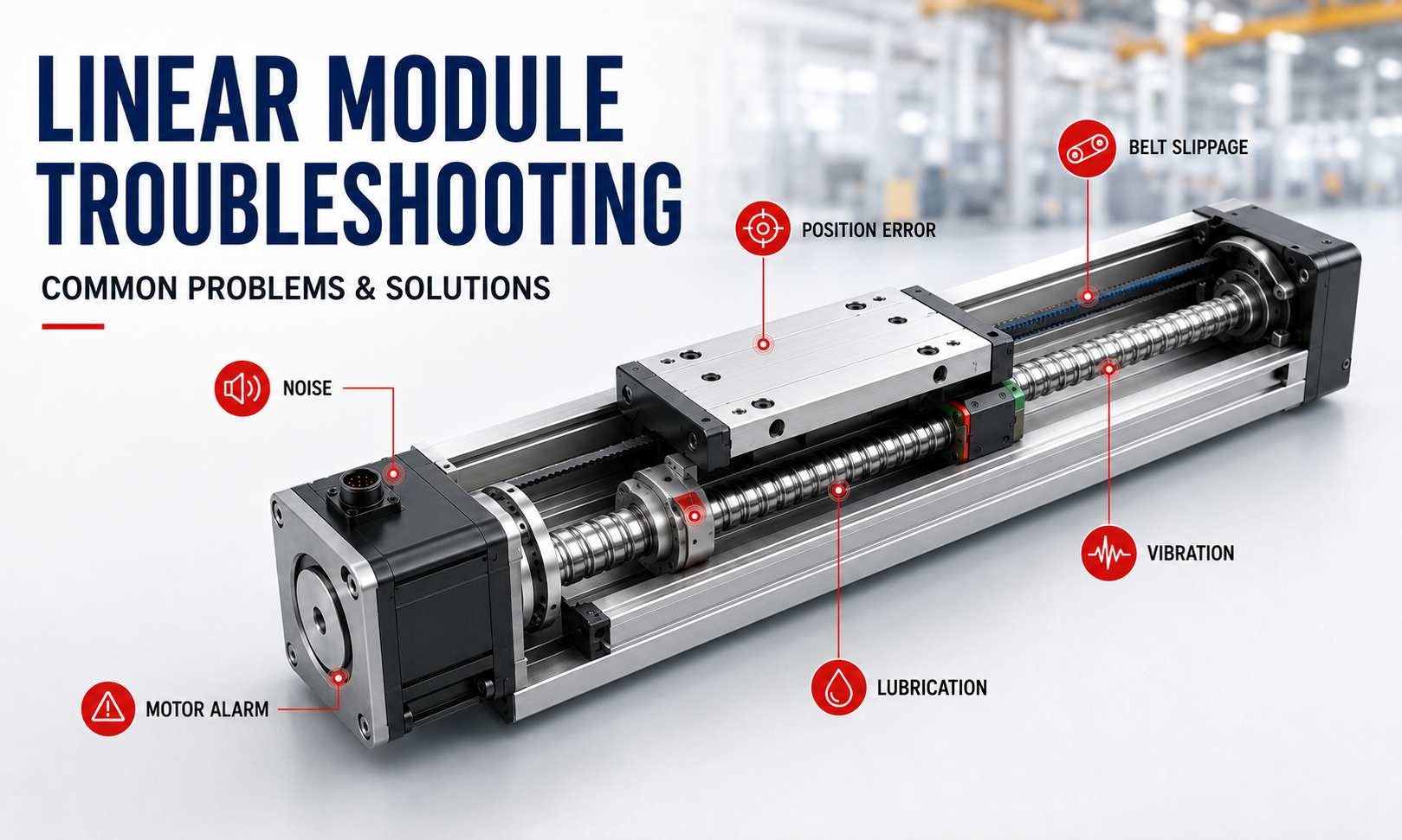
Linear module troubleshooting: establish the symptom
Reliable linear module troubleshooting follows a symptom-confirmation, safe-stop, cause-separation, measurement, correction and verification sequence. Check alignment, lubrication, looseness and transmission condition before attributing the problem to the motor, drive, sensor or controller.
Mechanical and transmission causes
Positioning Errors
Positioning Errors should be separated into systematic position error, reversal error and random repeatability loss. Compare commanded and measured carriage position at multiple points and from both approach directions, while recording load and temperature. A consistent travel-dependent trend suggests geometry or transmission error; a direction-dependent jump suggests backlash; changing scatter points to looseness, friction, vibration or feedback instability.
Excessive Noise
Excessive Noise should be classified by location, frequency and relationship to speed or position. A once-per-revolution tone points toward a rotating element, a tooth-frequency tone toward belt or gear mesh, and a local stroke-dependent sound toward alignment, contamination or a damaged raceway. Inspect at reduced speed, compare motor current, and correct the cause before noise develops into wear.
Vibration
Vibration can come from structural resonance, aggressive control gains, poor alignment, rotating imbalance, tooth-mesh variation or an S-curve that is too abrupt. Measure where vibration is strongest and whether its frequency follows motor speed, mesh frequency or the machine structure. Change one variable at a time and verify that the correction does not merely move resonance to another operating speed.
Control, sensor and drive evidence
Reduced Accuracy
Reduced Accuracy should be separated into systematic position error, reversal error and random repeatability loss. Compare commanded and measured carriage position at multiple points and from both approach directions, while recording load and temperature. A consistent travel-dependent trend suggests geometry or transmission error; a direction-dependent jump suggests backlash; changing scatter points to looseness, friction, vibration or feedback instability.
Lubrication Failure
Lubrication Failure must create the correct film at rolling or sliding contacts without attracting excessive contamination. Use a lubricant compatible with the component and environment, deliver it to the actual contact path, and avoid mixing incompatible products. Too much lubricant can raise drag, heat and leakage just as too little accelerates wear.
Corrective action and recurrence prevention
Engine Alarm
Motor Alarm is evidence, not a diagnosis. Record the exact alarm, axis position, commanded profile, load and whether the event occurs during acceleration, constant speed, deceleration or holding. Mechanical binding and brake timing can cause overcurrent or following-error alarms, while wiring, encoder and drive faults require electrical checks after the axis is proven mechanically free.
Belt Slippage
Belt Slippage may mean tooth jump rather than smooth frictional slip. Check tension by the approved method, pulley tooth condition, alignment, wrap and peak acceleration load; mark the belt and pulley to confirm relative movement. Raising tension without finding overload or tooth damage can increase bearing load and shorten belt life.
Verification before return to service
Ball Screw Wear
Ball Screw Wear should be confirmed from surface condition, backlash or tension trend, debris and position-dependent noise rather than assumed from operating hours. Identify the cause—load concentration, contamination, poor lubrication, misalignment or shock—before replacing the part, and inspect mating components that shared the damaged contact.
Preventive Solutions
Preventive Solutions should convert root causes into controls: clean datums, documented alignment, correct lubricant and tension, protected cables, alarm history and periodic trend measurements. Baseline current, temperature, noise and positioning after commissioning, then set intervention limits before process quality is affected.
Related engineering searches such aslinear module problems, linear module repair, linear module troubleshooting guide, common linear module problemspoint to the same decision discipline: define the operating case first, then verify the mechanics and controls with measurable evidence. The phrases do not replace load data or acceptance criteria.
Engineering takeaway
A reliable linear module troubleshooting decision comes from a defined operating case, a correct load path and verification of the assembled axis. Focus on Positioning Errors, Excessive Noise, Vibration, while recording load, speed, temperature, maintenance state and acceptance method so the selection or corrective action remains traceable in service.
