 English

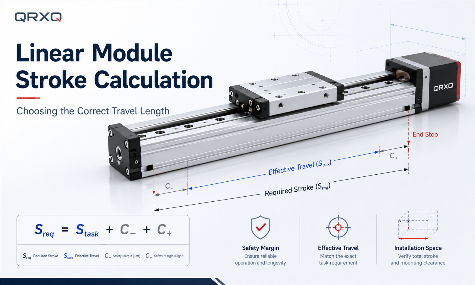
Alinear modulestroke calculation converts the workpiece motion, tooling geometry, end clearances, stopping behavior, and machine envelope into one required travel length. The number is not simply the distance between two process points. The module carriage may need extra travel for pickup approach, tool clearance, homing, controlled stopping, calibration, and future adjustment.
Choosing too little stroke can make an otherwise suitable module impossible to commission because the tool cannot reach every position without entering a limit or buffer zone. Choosing excessive stroke increases the module length, moving mass, screw or belt span, installation space, cable-carrier travel, and often cost. On long ball-screw axes it can also make critical-speed and buckling checks more demanding.
This guide builds the required stroke from a common coordinate system, shows how to allocate margins at both ends, calculates a speed-dependent stopping allowance, and completes a worked teaching example. All numerical data in the example are hypothetical and demonstrate the method only; they are not specifications for a QRXQ product, test results, or data from a customer project.
What does stroke mean on a linear module?
Nominal strokeis the travel stated for a module configuration.Effective travelis the portion that the machine can actually use after accounting for limit positions, buffers, hard stops, homing strategy, tooling clearances, and any restricted end zones.Process travelis the carriage movement required to complete the task itself.
These terms must not be treated as interchangeable. A module with 900 mm nominal stroke does not automatically provide a safe 900 mm process move. The usable interval depends on the exact product drawing, switch arrangement, stop geometry, control settings, installation, and tooling envelope.
| Term | Engineering meaning | Typical source |
|---|---|---|
| Process positions | All tool-center or workpiece coordinates required by every operating recipe | Machine layout and process plan |
| Carriage positions | Process positions transformed to the module carriage datum | Tooling geometry and coordinate model |
| Process travel | Difference between the maximum and minimum required carriage positions | Calculated from the position list |
| End allowance | Reserved travel beyond the process range at each end | Process, control, stopping, and service requirements |
| Required stroke | Process travel plus the separately justified allowances at both ends | Engineering calculation |
| Nominal stroke | Catalog or drawing value for a selectable module configuration | Confirmed manufacturer documentation |
| Installation envelope | Space occupied by the complete module, motor, cables, connectors, and service access | Product drawing and machine layout |
Start with one coordinate system and the real tool point
Define a machine coordinate axis before adding margins. Record every required process position in the same coordinate system, including load, unload, inspection, reject, cleaning, and maintenance positions when they are part of normal automatic motion. Using only the nominal distance between two stations can miss a farther tool-clearance or service position.
The process specification usually describes the tool center point, gripper fingers, nozzle, camera field center, or workpiece datum rather than the module carriage datum. Convert each required tool position to the carriage position:
Carriage coordinate:x_c,i = x_tool,i - o_i
Here, x_c,i is the carriage datum coordinate for state i, x_tool,i is the required tool-point coordinate, and o_i is the signed offset from the carriage datum to the tool point. The signs must follow the selected coordinate direction.
If the tool offset is constant, it changes the absolute placement of the module but cancels out of the basic point-to-point span. If the tool rotates, changes grippers, extends a slide, or carries products of different lengths, o_i can change. Every relevant state must then be transformed separately before calculating the range.
The minimum task travel is the range of all required carriage coordinates:
Task travel:S_task = max(x_c,i) - min(x_c,i)
This range method is safer than adding individual moves because stroke is governed by the two extreme carriage positions, not by the sum of distances traveled during a cycle.
Build the two end allowances from physical requirements
Reserve the negative-end allowance C_- and positive-end allowance C_+ separately. They do not have to be equal. A loading side may require a gripper back-off distance, while the opposite side may need a larger stopping distance, connector clearance, or inspection overtravel.
| Allowance component | Why it may consume travel | How to determine it |
|---|---|---|
| Process approach or back-off | The tool must approach, retract, clear a fixture, or move beyond a sensing point | Process sequence, tooling model, and collision study |
| Part and fixture tolerance | The required point can shift with product size, nest adjustment, or setup variation | Tolerance stack and recipe range |
| Homing and limit-switch zone | The carriage needs a repeatable home sequence without entering a forbidden region | Sensor arrangement, control logic, and product drawing |
| Controlled stopping allowance | The moving axis travels during command reaction and deceleration | Validated speed, reaction time, deceleration, and load condition |
| Buffer or hard-stop clearance | Normal operation must remain outside mechanical end-stop engagement | Manufacturer drawing and safety concept |
| Thermal or calibration reserve | Coordinate correction or thermal growth may shift the required carriage position | Error budget and environmental analysis |
| Future process adjustment | A known product-family range may require a wider operating interval | Approved machine specification, not an arbitrary percentage |
Do not add the same uncertainty more than once. For example, if the process-coordinate range already includes every product size, adding a second full product-size allowance would double count it. Each margin should have an owner, a physical reason, and a documented value.
When speed affects the required end margin
Stroke is a geometric requirement, but the safe distance between the normal end position and a restricted end zone can depend on speed. For a preliminary constant-deceleration check, the controlled stopping distance can be estimated as:
Controlled stopping distance:d_stop = v × t_r + v² ÷ (2 × a_d)
| Symbol | Meaning | Unit |
|---|---|---|
| d_stop | Distance traveled during reaction and controlled deceleration | m or mm |
| v | Axis speed when the stop command begins | m/s or mm/s |
| t_r | Total validated reaction time before the assumed deceleration is established | s |
| a_d | Available deceleration magnitude under the evaluated load and drive condition | m/s² or mm/s² |
This formula assumes speed is constant during the reaction interval and deceleration is then constant. It is not a substitute for a machine safety assessment, a servo drive's verified stop performance, or the manufacturer's end-stop limits. Power loss, drive faults, vertical loads, brake timing, regenerative limits, jerk-limited profiles, controller scan time, and communication delay may require a different model and a larger validated distance.
Normal process motion should be planned to stop before the software limit. Software limits should normally be inside hardware limit-switch positions, and mechanical buffers or hard stops should remain outside the normal control zone. Exact ordering and distances must follow the selected module, controls, and risk assessment.
Calculate the required stroke
After the extreme carriage positions and justified end allowances are known, calculate:
Required stroke:S_req = S_task + C_- + C_+
| Symbol | Meaning | Unit | Calculation rule |
|---|---|---|---|
| x_tool,i | Required tool-point coordinate for state i | mm | Input from the process layout |
| o_i | Signed tool offset from carriage datum for state i | mm | Input from the tooling model |
| x_c,i | Required carriage coordinate for state i | mm | x_tool,i - o_i |
| S_task | Travel between the extreme required carriage positions | mm | max(x_c,i) - min(x_c,i) |
| C_- | Total justified allowance at the negative end | mm | Sum of non-overlapping negative-end requirements |
| C_+ | Total justified allowance at the positive end | mm | Sum of non-overlapping positive-end requirements |
| S_req | Minimum required effective stroke | mm | S_task + C_- + C_+ |
| S_name | Selected nominal catalog stroke | mm | Confirmed available value not less than S_req |
Select a nominal stroke that is available for the actual product family and is not less than S_req. Do not assume that every arbitrary length is manufacturable. After selection, allocate the excess stroke intentionally between the two ends and update the module mounting coordinate.
For several machine recipes, calculate x_c,i for every recipe and use the global minimum and maximum. If tooling is changed manually, include the worst approved configuration or define a controlled setup that prevents an incompatible tool from being used with the selected axis.
Worked example: pick-and-place axis with unequal end margins
Teaching-data statement:The following values are hypothetical and are used only to demonstrate linear module stroke sizing. They do not represent a QRXQ model, catalog dimension, verified stop distance, or customer machine.
Input positions and tooling states
A horizontal pick-and-place axis moves a gripper between several machine coordinates. Positive travel is to the right. The gripper center is 40 mm to the right of the carriage datum in all listed states.
| State | Tool-point coordinate x_tool,i | Tool offset o_i | Carriage coordinate x_c,i |
|---|---|---|---|
| Pick approach | 120 mm | 40 mm | 80 mm |
| Pick retract | 165 mm | 40 mm | 125 mm |
| Vision inspection | 510 mm | 40 mm | 470 mm |
| Place position | 870 mm | 40 mm | 830 mm |
Step 1: calculate task travel
The extreme carriage positions are 80 mm and 830 mm:
S_task = 830 - 80 =750 mm
The intermediate positions affect the motion profile and cycle time, but they do not increase the stroke because they lie inside the two extremes.
Step 2: calculate a preliminary controlled stopping distance
Assume the positive-end approach can occur at 0.30 m/s, the validated control reaction time is 0.020 s, and the available controlled deceleration magnitude is 2.5 m/s² under the evaluated load:
Reaction distance = 0.30 × 0.020 = 0.006 m =6 mm
Deceleration distance = 0.30² ÷ (2 × 2.5) = 0.018 m =18 mm
d_stop = 6 + 18 =24 mm
For this teaching example, the engineering team reserves 30 mm for the positive-end controlled stopping component. The extra 6 mm is an explicit project allowance for model and setting variation; it is not a universal safety factor.
Step 3: build the negative and positive end allowances
| End | Allowance component | Value |
|---|---|---|
| Negative | Pick-side approach and fixture clearance | 20 mm |
| Negative | Home and hardware-limit separation | 25 mm |
| Negative | Calibration reserve | 5 mm |
| Positive | Place-side retract and product-family adjustment | 35 mm |
| Positive | Controlled stopping component | 30 mm |
| Positive | Calibration reserve | 5 mm |
C_- = 20 + 25 + 5 =50 mm
C_+ = 35 + 30 + 5 =70 mm
Step 4: calculate and select the stroke
S_req = 750 + 50 + 70 =870 mm
Assume the candidate product family offers a confirmed 900 mm nominal stroke. The preliminary selection is therefore:
S_name =900 mm, which leaves 900 - 870 =30 mmof additional travel.
If the task interval is placed from module coordinate 50 mm to 800 mm, the negative side retains 50 mm and the positive side retains 100 mm. This satisfies the planned 50 mm and 70 mm allowances and assigns the extra 30 mm to the positive side, where stopping and future product adjustment are more demanding.
Step 5: check the machine installation envelope
Stroke alone does not prove that the module fits. Assume a hypothetical drawing for the candidate configuration shows a complete module envelope of 1,180 mm including its selected motor arrangement. The machine layout also requires 120 mm of drive-end assembly access and 60 mm of opposite-end service access:
Required bay length = 1,180 + 120 + 60 =1,360 mm
If the available bay is 1,420 mm, the static length check leaves60 mm. The design is not released until the cable bend radius, connector removal path, moving cable loop, gripper sweep, guards, fasteners, and adjacent equipment are also checked in the full motion model.
Effective travel must remain outside restricted end zones
After selecting S_nom, obtain the manufacturer's dimensioned drawing and identify the reference points for nominal stroke. Confirm whether the stated endpoints refer to carriage-center positions, mechanical contact positions, switch positions, or another datum. Never infer the usable range from the extrusion length or overall module length.
Create a position schedule with at least the following coordinates:
- Mechanical negative limit or buffer-contact position.
- Negative hardware limit-switch position.
- Negative software limit.
- Minimum normal process position.
- Maximum normal process position.
- Positive software limit.
- Positive hardware limit-switch position.
- Mechanical positive limit or buffer-contact position.
The order must be physically and logically consistent in the selected coordinate direction. The exact separation between these positions is product- and control-specific. Verify switch repeatability, actuator width, sensing flag geometry, braking behavior, and the ability to recover from an overtravel without creating a new collision.
How drive type changes the stroke-selection checks
The geometric calculation is common to ball-screw, belt-driven, rack-and-pinion, and linear-motor axes, but a longer selected stroke changes different mechanical limits.
| Drive type | Stroke-related checks after geometry is complete | Common design concern |
|---|---|---|
| Ball screw | Available screw length, support arrangement, critical speed, compression buckling, lead accuracy, lubrication, and life | A longer screw can reduce allowable rotational speed or stiffness |
| Timing belt | Belt length, tension, tooth engagement, pulley loads, elastic stretch, natural frequency, and repeatability over the span | Long travel can increase compliance and settling time |
| Rack and pinion | Rack section joints, lubrication, tooth rating, gearbox load, backlash, and structural alignment | Long axes require careful rack alignment and joint management |
| Linear motor | Magnet-track segmentation, cable travel, encoder scale, thermal behavior, continuous force, and end-stop energy | There is no rotary transmission, but long direct-drive travel still needs accurate guidance and cable management |
A vertical or inclined installation usually does not change the geometric process span, but it can change the stopping distance, brake behavior, fault travel, and safe end-zone design. Gravity-assisted downward motion and power-loss conditions require specific analysis. A counterbalance may also create its own travel and collision envelope.
Check installation space separately from travel length
The selected module's overall length is normally greater than its stroke because it includes end supports, motor mounts, bearing housings, covers, and other structure. Motor orientation can change the required drive-end space: inline, folded-belt, side-mounted, or gearbox arrangements may have different envelopes even when the nominal stroke is identical.
The complete moving envelope must include the workpiece, gripper fingers, hoses, electrical connectors, cable carrier, sensor targets, and any vertically or laterally extending tooling. Check the envelope at intermediate positions as well as both ends. A tool can clear the machine at its endpoints and still collide during a rotation or diagonal motion between them.
Provide service access for coupling installation, lubrication, belt tensioning, switch adjustment, cover removal, fastener tools, and motor replacement. If servicing requires removing the entire axis, record that as a deliberate maintenance strategy rather than discovering it after assembly.
Verify the selected stroke before releasing the design
- Audit every operating recipe:confirm that the global minimum and maximum carriage coordinates include all approved products, tools, rejects, cleaning positions, and recovery moves.
- Run a 3D collision check:sweep the complete moving assembly through the calculated interval, including cable and hose envelopes.
- Confirm end-zone geometry:locate software limits, hardware switches, buffers, and hard stops from real drawings rather than assumed offsets.
- Validate stopping behavior:test the intended speed, load, reaction time, deceleration, brake behavior, and regenerative limits under controlled commissioning conditions.
- Check the transmission:verify that the chosen stroke and speed comply with screw, belt, rack, linear-motor, guide, bearing, and structure limits.
- Check accuracy across the full range:confirm positioning accuracy, repeatability, straightness, stiffness, and thermal effects at the actual working positions.
- Measure effective travel during commissioning:record the final usable process interval and retain it with the software-limit and home-offset settings.
Common mistakes in linear module stroke calculation
- Using the distance between station centerlines without transforming the real tool point to the carriage datum.
- Adding all moves in a cycle instead of using the difference between the extreme required carriage coordinates.
- Treating nominal stroke, effective travel, process travel, extrusion length, and overall module length as the same dimension.
- Applying one arbitrary percentage margin without identifying the physical requirement it covers.
- Using equal margins at both ends when the process, homing, stopping, or service conditions are asymmetric.
- Ignoring a changing tool offset caused by gripper rotation, extension, tool change, or product-size variation.
- Using a stopping-distance formula without verified reaction time, load-dependent deceleration, vertical-axis behavior, or fault conditions.
- Allowing normal process positions to overlap software limits, hardware switches, buffers, or mechanical stops.
- Selecting the next nominal stroke without checking whether the complete module and motor fit the machine bay.
- Checking only endpoint collisions and missing the intermediate sweep of tooling, cables, hoses, or a rotating workpiece.
- Increasing ball-screw stroke without checking critical speed, buckling, support arrangement, and life.
- Leaving spare stroke unallocated, which makes the module mounting coordinate and end clearances ambiguous.
Data to prepare for final stroke sizing
- Machine coordinate convention and the selected carriage reference datum.
- All required tool-center, workpiece, inspection, reject, cleaning, homing, and recovery positions.
- Tool offsets for every gripper, product, tool orientation, and extension state.
- Fixture and product tolerance ranges that can move the required coordinates.
- Maximum speed at each end, motion profile, validated reaction time, available deceleration, and load range.
- Software-limit, hardware-switch, buffer, and hard-stop positions from confirmed drawings and control requirements.
- Selected drive type, nominal stroke options, module overall dimensions, motor orientation, and support arrangement.
- Cable-carrier bend radius, hose and connector envelopes, and required service access.
- Available machine bay dimensions and full 3D collision model.
- Accuracy, repeatability, rigidity, thermal, environmental, life, and safety requirements across the full travel.
Selection conclusion
A defensible linear module stroke calculation starts with every required tool position, converts those positions to the carriage datum, finds the extreme carriage coordinates, and adds separately justified allowances at the negative and positive ends. The result is then rounded up only to a confirmed available nominal stroke, with any excess travel deliberately allocated.
In the hypothetical example, the task travel is 750 mm, the two end allowances are 50 mm and 70 mm, and the required stroke is 870 mm. A confirmed 900 mm nominal option would satisfy the preliminary geometric requirement and leave 30 mm of additional travel. The selection is not complete until the actual module drawing, restricted end zones, controlled stopping behavior, transmission limits, complete installation envelope, cable sweep, accuracy, and safety functions have all been verified.
