 English

Linear module load calculationis a design verification process rather than a simple comparison between payload mass and a catalog load rating. A reliable calculation must describe the complete operating condition, including the moving mass, mounting orientation, acceleration, external process forces, load center of gravity, motion cycle and expected service life.
Alinear modulecontains several load-bearing and force-transmitting elements. The guide system supports the payload and resists roll, pitch and yaw moments, while the drive mechanism generates the thrust required to accelerate the moving mass and overcome friction, gravity and process resistance. The motor, coupling, bearings, module body and mounting structure must also remain within their respective limits.
This guide explains how to calculate horizontal and vertical linear module loads, determine offset moments, convert thrust into motor torque, distinguish static and dynamic ratings, apply safety margins and complete a practical selection check.
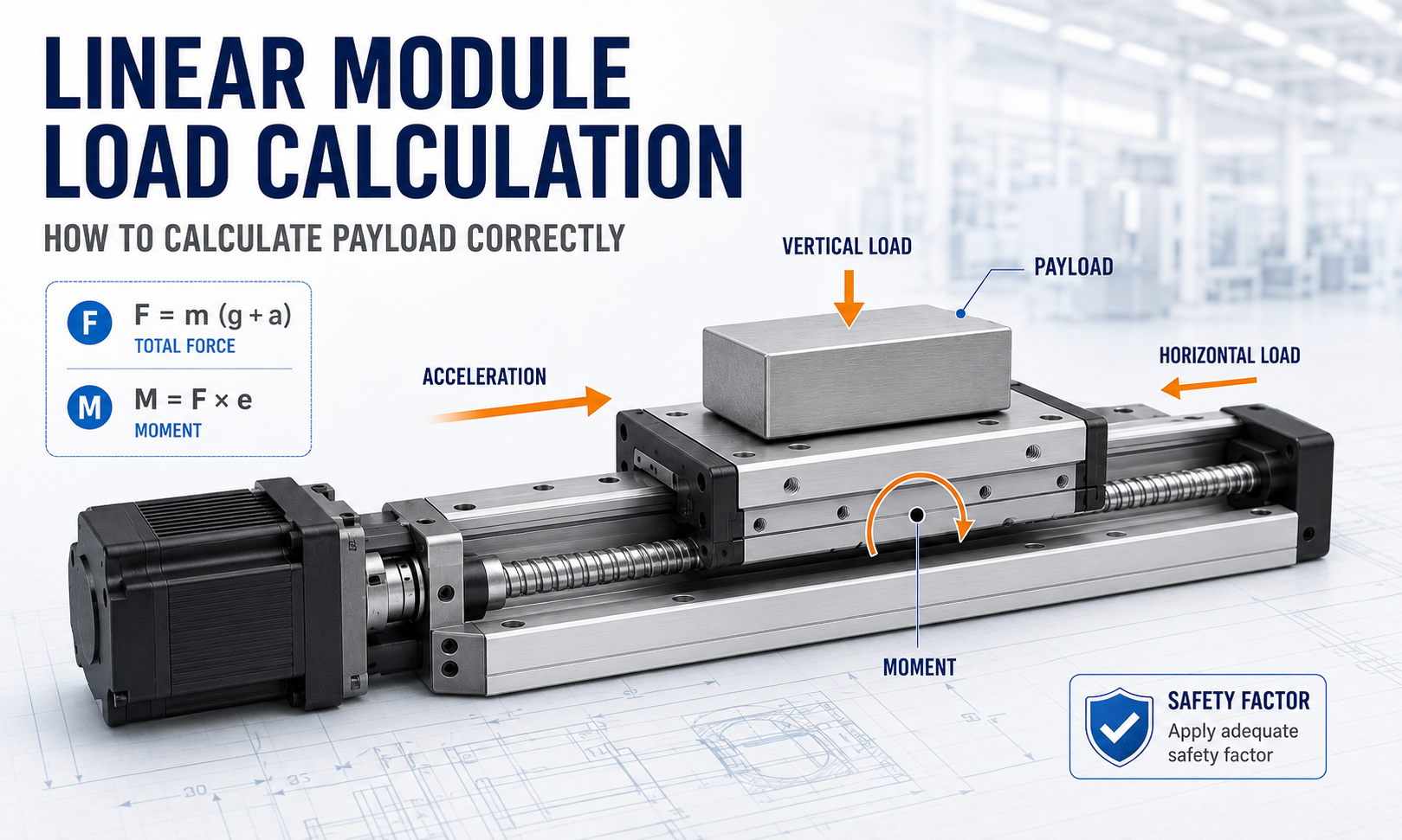
What Must Be Checked in a Linear Module Load Calculation?
A complete load calculation does not produce only one result. Different components are governed by different forces, moments and rating definitions. The guide system may be limited by static load, dynamic load or allowable moment, while the drive system may be limited by peak thrust, continuous thrust, motor torque, transmission strength or bearing capacity.
The calculation should therefore answer the following questions:
- What total mass moves with the carriage?
- What thrust is required during acceleration, constant-speed travel and deceleration?
- How does the result change between horizontal, vertical and inclined mounting?
- What roll, pitch and yaw moments are created by the load offset?
- What motor torque is required after transmission efficiency is considered?
- Can the guide withstand the maximum static load and moment?
- Will the guide and transmission provide the required operating life?
- Is sufficient margin available for shock, friction variation, assembly error and future load changes?
Calculation path:define the operating case, calculate forces and moments at the carriage, convert the required thrust through the transmission, and then check the guide, drive, motor, bearings and structure separately.
Define the Calculation Inputs
The calculation should begin with the worst credible operating case rather than the average production condition. An axis that operates safely during normal travel may still be overloaded during rapid acceleration, emergency deceleration, tool contact or power-off holding.
The moving mass must include every component that moves with the carriage:
- Workpiece or payload
- Fixture and tooling
- Carriage-mounted motor or actuator
- End effector, gripper, camera or dispensing head
- Moving cable, hose and drag-chain mass
- Adapter plates and mounting brackets
- Any portion of another axis carried by the module
| Symbol | Meaning | Typical Unit |
|---|---|---|
| m | Total moving mass | kg |
| g | Gravitational acceleration | 9.81 m/s² |
| a | Linear acceleration or deceleration | m/s² |
| m | Equivalent friction coefficient | Dimensionless |
| F | Force or required thrust | N |
| e | Perpendicular distance from the load line to the reference point | m |
| M | Moment load | N·m |
| p | Ball screw lead | m/rev or mm/rev |
| r | Pulley or pinion pitch radius | m |
| or | Transmission efficiency | Dimensionless |
| T | Required drive torque | N·m |
All units must be made consistent before substitution. A common error is mixing millimeters with meters when calculating torque or moment. For example, an offset of 120 mm must be entered as 0.12 m when the required result is expressed in N·m.
Separate Guide Load from Drive Force
The payload supported by the guide is not automatically equal to the thrust required from the drive. These are two related but different calculations.
The guide system carries vertical, lateral and moment loads. The drive system generates force along the axis of travel. In a horizontal installation, the guide may support the full payload weight while the motor only needs to overcome acceleration, friction, cable resistance and external process force.
For this reason, a linear module can have sufficient motor thrust but insufficient guide moment capacity. The opposite is also possible: the guide may support the payload, but the motor or transmission may be unable to accelerate it at the required rate.
Load Types Used in Linear Module Selection
Payload Mass
Payload mass describes the physical mass placed on the carriage, but it is only an input to the calculation. It does not describe acceleration force, gravity force, offset moment, shock load or process resistance.
Continuous Load
Continuous load represents the force or torque that acts for a significant portion of the operating cycle. It is important for motor heating, bearing temperature, transmission wear and long-term reliability.
Peak Load
Peak load occurs during acceleration, deceleration, reversal, impact or short-duration process operations. Peak motor torque and peak transmission capacity must be checked separately from continuous ratings.
Static Load
Static load is used to evaluate the risk of permanent deformation at the rolling contacts, bearings, carriage or structure. The worst static condition may occur while the machine is stopped, transported, impacted or subjected to an emergency stop.
Dynamic Load
Dynamic load is associated with fatigue life under repeated motion. It is not the maximum instantaneous load. The equivalent dynamic load must reflect the real load spectrum, duty cycle, operating direction and load distribution.
Moment Load
Moment load is generated when the center of gravity or process force does not act through the carriage reference point. Even a relatively light payload can exceed the allowable moment if it is mounted far from the carriage.
Horizontal Linear Module Load Calculation
For a horizontal axis, gravity is normally perpendicular to the travel direction. The guide supports the weight, while the drive generates the force required to accelerate the moving mass and overcome resistance.
A practical horizontal drive-force equation is:
F_horizontal = ma + μmg + F_cable + F_seal + F_process
Where:
- mais the inertial force required for acceleration.
- μmgrepresents estimated friction resistance when an equivalent friction coefficient is used.
- F_cableis the force created by cable carriers, hoses or moving wiring.
- F_sealrepresents additional resistance from seals, covers or protective structures.
- F_processis the external force caused by machining, pressing, dispensing, gripping or another operation.
The friction term should not be estimated carelessly. Use measured values, verified component data or a conservative engineering estimate appropriate to the guide type, lubrication condition, sealing system and mounting accuracy.
The horizontal guide load is evaluated separately. Under static conditions, the vertical guide force begins with:
F_guide = mg + F_external,vertical
This force must then be distributed through the carriage and combined with any roll, pitch or yaw moments produced by the load position.
Vertical Linear Module Load Calculation
In a vertical axis, gravity acts directly along the travel direction. The motor must generate sufficient force not only to accelerate the payload but also to support it against gravity.
When upward travel is defined as the positive direction, a general signed-force model is:
F_drive = ma + mg + F_resistance + F_process
The sign of acceleration and external process force must follow the selected coordinate direction. This allows upward acceleration, upward deceleration, downward acceleration and downward braking to be evaluated consistently.
Upward Acceleration
During upward acceleration, acceleration and gravity act in the same required motor-force direction:
F_up,accel = m(g + a) + F_resistance + F_process
This condition commonly produces the maximum lifting thrust.
Upward Constant-Speed Travel
When acceleration is zero:
F_up,constant = mg + F_resistance + F_process
Upward Deceleration
During upward deceleration, the acceleration vector acts downward. When the deceleration magnitude is lower than gravitational acceleration:
F_up,decel = m(g - a_decel) + F_resistance + F_process
The exact motor torque may be lower than during upward acceleration, but regeneration and braking behavior still require verification.
Downward Acceleration
During downward acceleration, gravity assists the motion. Depending on the requested acceleration, friction and process force, the motor may provide reduced lifting force or operate in a braking condition.
Using acceleration magnitude in the downward direction:
F_down,accel = m(g - a_down) + F_resistance + F_process
If the requested downward acceleration exceeds the natural gravitational acceleration after resistance is considered, the drive must actively pull the load downward. If gravity produces more acceleration than required, the motor must absorb energy and control the descent.
Downward Deceleration
Decelerating a downward-moving load requires an upward acceleration. This can produce a high motor force:
F_down,decel = m(g + a_decel) + F_resistance + F_process
For many vertical applications, downward deceleration is as important as upward acceleration.
Holding and Power-Off Conditions
Moving torque must not be used as the only basis for evaluating vertical holding safety. The calculation should separately verify:
- Motor holding torque
- Brake rated holding torque
- Transmission backdriving behavior
- Emergency-stop deceleration
- Power-off load retention
- Mechanical anti-fall protection where required
Calculate Roll, Pitch and Yaw Moments
A moment is produced when a force acts at an offset from the carriage reference point:
M = F × e
The distanceemust be measured perpendicular to the force direction. The calculation should distinguish the three principal moment directions.
| Moment | Typical Cause | Possible Effect |
|---|---|---|
| Roll moment | Payload mounted to one side of the carriage | Uneven loading between guide tracks |
| Pitch moment | Payload center of gravity positioned above or ahead of the carriage | Front-to-rear load imbalance and carriage deflection |
| Yaw moment | Lateral process force or offset along the travel plane | Side loading and unequal guide-block force |
Calculate moments for both gravity and dynamic forces. A high-mounted load may create a small static moment while stopped but a much larger moment during rapid acceleration.
For example:
M_dynamic = F_inertia × e_height
M_gravity = mg × e_lateral
M_process = F_process × e_process
Do not assume that passing each individual moment rating automatically proves that the combined load is acceptable. Use the combined-load equation or equivalent-load method specified by the module or guide manufacturer. Different guide arrangements may use different interaction equations.
Convert Linear Thrust into Drive Torque
After the required linear thrust has been calculated, it must be converted through the actual transmission. Transmission efficiency, reduction ratio, pulley radius and screw lead affect the required motor torque.
Ball Screw Linear Module
For a ball screw drive:
T_screw = Fp / (2πη)
Wherepis the screw lead in meters per revolution. When the lead is provided in millimeters per revolution, convert it to meters before calculating torque in N·m.
A larger lead increases linear travel per revolution but also increases the torque required for the same linear thrust.
Timing Belt Linear Module
For a timing belt drive:
T_pulley = Fr / h
Whereris the pitch radius of the driving pulley. Belt tension, pulley tooth engagement, belt tooth strength and shaft bearing load must also be checked.
Rack and Pinion Linear Module
For a rack and pinion drive:
T_pinion = Fr / h
Whereris the pinion pitch radius. The calculation must also consider gearbox ratio, gear-tooth load, backlash, lubrication and the required acceleration torque.
If a gearbox is used, convert torque and speed through the gearbox ratio while including gearbox efficiency. Peak motor torque, continuous motor torque and the motor speed-torque curve must all be checked.
Check Static Load, Dynamic Load and Service Life
Static Load Check
The maximum static force and moment should be compared with the applicable basic static load rating and static moment rating. The calculation should include foreseeable shock, emergency stopping, installation handling and temporary overload conditions.
A static safety factor may be expressed as:
f_static = C0 / P_max
WhereC0is the applicable basic static load rating andP_maxis the maximum equivalent static load. The required minimum factor must be selected according to the manufacturer's rating method, shock level, safety consequences and machine risk assessment.
Dynamic Load and Life Check
The equivalent dynamic load should represent repeated operating conditions rather than only the highest load. The load spectrum may include acceleration, constant-speed travel, process operation, return motion and idle time.
For many recirculating-ball guide systems, rated life is related to the ratio between the basic dynamic load rating and the equivalent dynamic load. However, the reference travel distance, correction factors and exact equation can vary between manufacturers.
Use the specific product catalog to confirm:
- Basic dynamic load rating
- Equivalent-load calculation method
- Life equation and reference travel distance
- Load-direction factors
- Hardness, temperature and reliability factors
- Moment-load conversion method
Do not combine a load rating from one manufacturer with a life equation or correction factor from another.
Apply Safety Factors and Engineering Margin
A safety factor covers uncertainty, but it cannot correct an incomplete force model. Before applying a margin, make sure that the calculation already includes the actual moving mass, acceleration, gravity, friction, process force, load offset and transmission efficiency.
Additional margin may be required for:
- Shock or vibration
- Rapid direction reversal
- Uncertain friction
- Long-term lubrication deterioration
- Installation misalignment
- High temperature or contamination
- Flexible mounting structures
- Future payload increases
- Safety-critical vertical motion
There is no single safety factor suitable for every linear module. The required margin should follow the component rating basis, operating environment, duty cycle and machine risk level.
Worked Linear Module Load Calculation Example
The following example demonstrates the calculation method. The values are hypothetical and are provided only for engineering illustration. They do not represent a specific QRXQ product model or customer application.
Operating Conditions
| Parameter | Value |
|---|---|
| Mounting orientation | Horizontal |
| Total moving mass | 25 kg |
| Maximum acceleration | 2.5 m/s² |
| Equivalent friction coefficient | 0.01 |
| Cable drag | 20 N |
| External process force | 35 N |
| Ball screw lead | 20 mm/rev |
| Estimated transmission efficiency | 0.90 |
| Center-of-gravity lateral offset | 80 mm |
| Center-of-gravity height | 120 mm |
| Process-force offset | 150 mm |
Step 1: Calculate Inertial Force
F_inertia = ma
F_inertia = 25 × 2.5 = 62.5 N
Step 2: Estimate Friction Force
F_friction = μmg
F_friction = 0.01 × 25 × 9.81 = 2.45 N
Step 3: Calculate Required Horizontal Thrust
F_horizontal = F_inertia + F_friction + F_cable + F_process
F_horizontal = 62.5 + 2.45 + 20 + 35 = 119.95 N
The calculated operating thrust is therefore approximately120 Nbefore additional design margin is applied.
Step 4: Calculate Ball Screw Torque
Convert the 20 mm lead to meters:
p = 20 mm/rev = 0.020 m/rev
T_screw = Fp / (2πη)
T_screw = 119.95 × 0.020 / (2 × 3.1416 × 0.90)
T_screw = 0.424 N·m
The calculated screw torque is approximately0.42 N·m. This result does not yet include rotating inertia, coupling losses, bearing drag, motor reserve or a selected engineering safety margin.
Step 5: Calculate Static Guide Force
F_weight = mg
F_weight = 25 × 9.81 = 245.25 N
The guide must support at least245.25 Nof vertical weight, in addition to any external vertical force and moment effects.
Step 6: Calculate Roll Moment from the Lateral Offset
M_roll = F_weight × e_lateral
M_roll = 245.25 × 0.080 = 19.62 N·m
Step 7: Calculate Pitch Moment from Acceleration
M_pitch,inertia = F_inertia × e_height
M_pitch,inertia = 62.5 × 0.120 = 7.50 N·m
Step 8: Add the Process-Force Moment
M_pitch,process = F_process × e_process
M_pitch,process = 35 × 0.150 = 5.25 N·m
When both moments act in the same direction:
M_pitch,total = 7.50 + 5.25 = 12.75 N·m
Step 9: Complete the Selection Check
The example calculation produces the following preliminary requirements:
| Calculated Requirement | Result | Catalog Check Required |
|---|---|---|
| Horizontal operating thrust | Approximately 120 N | Peak and continuous drive thrust |
| Ball screw torque | Approximately 0.42 N·m | Motor torque, screw torque and coupling rating |
| Vertical guide load | 245.25 N | Static and dynamic guide load |
| Roll moment | 19.62 N·m | Allowable roll moment |
| Total pitch moment | 12.75 N·m | Allowable dynamic pitch moment |
A module should not be approved only because its nominal payload exceeds 25 kg. The selected model must satisfy the required thrust, torque, static load, dynamic load, combined moment and target life under the same operating condition.
Common Linear Module Load Calculation Mistakes
- Comparing payload mass directly with the catalog load rating without calculating force and moment.
- Excluding the fixture, tooling, adapter plate, cable carrier or moving secondary axis from the total mass.
- Using payload weight as the horizontal drive force.
- Ignoring acceleration and checking only constant-speed travel.
- Using the same force equation for horizontal and vertical mounting.
- Ignoring the load center of gravity because the total payload is below the nominal limit.
- Checking motor torque without checking guide moment capacity.
- Checking peak torque without checking continuous torque and motor heating.
- Using a static load rating as if it were a dynamic-life rating.
- Mixing millimeters and meters in torque or moment calculations.
- Applying a safety factor before all real forces have been included.
- Using assumed catalog values without identifying the product model and rating basis.
Information Required for Linear Module Selection
To complete a practical linear module payload calculation, prepare the following project information:
- Total moving mass
- Payload dimensions and center-of-gravity position
- Horizontal, vertical or inclined mounting orientation
- Stroke and available installation length
- Maximum speed
- Acceleration and deceleration
- Motion cycle and operating hours
- External process forces
- Required positioning accuracy and repeatability
- Environmental conditions
- Required service life
- Motor, gearbox and controller requirements
- Emergency-stop and power-off safety requirements
Engineering Takeaway
A reliablelinear module load calculationmust connect the actual operating condition with the separate limits of the guide, drive, motor, bearings and structure. Payload mass alone cannot describe the required thrust, allowable moment or expected service life.
Begin by defining the total moving mass, mounting orientation, acceleration, friction, process force and load offset. Calculate horizontal or vertical thrust, determine roll, pitch and yaw moments, convert the thrust into transmission torque, and then compare every result with the relevant peak, continuous, static, dynamic and life rating.
The final selection should remain traceable: record the input values, units, assumptions, formulas, catalog ratings, applied margins and acceptance method. This makes the result easier to review during machine design, commissioning, maintenance and future payload changes.
