 English

Rack and pinionlinear modulesare widely used for long-travel, high-speed and heavy-duty motion because the drive length can be extended without requiring one long rotating screw. But “rack and pinion module” covers several very different structures.
The most useful way to understandrack and pinion linear module typesis to classify them by tooth form, drive arrangement, preload method, protection level and machine architecture. A straight rack with one pinion, a helical rack with dual preloaded pinions, an enclosed long-travel axis and a dual-side heavy gantry may all belong to the same product family while having very different performance.
This guide explains the major rack module designs and shows where straight racks, helical racks, single- and dual-pinion drives, single- and dual-side rack layouts, open/enclosed structures and heavy-duty configurations fit best.
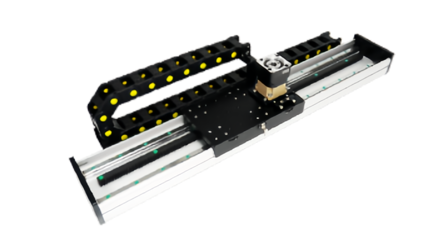
Rack and Pinion Modules Can Be Classified in Several Dimensions
- Straight-tooth or helical-tooth rack
- Single-pinion or dual-pinion drive
- Single-side or dual-side rack drive
- Open, semi-enclosed or enclosed module
- Standard, wide-body or heavy-duty structure
- Single carriage or gantry carriage
- Single motor or synchronized dual motor
- Single rack section or multi-section long travel
Important:these are different classification dimensions. A module can be helical, dual-pinion, enclosed and heavy-duty at the same time.
Straight Rack Linear Modules
A straight rack uses teeth perpendicular to the direction of travel. The mating pinion has straight teeth as well.
Typical advantages include:
- Simple tooth geometry
- Easy manufacturing and inspection
- Good efficiency
- No axial gear-thrust component from helix angle
- Broad availability
- Cost-effective long-travel motion
Where straight rack modules are commonly used
- Material handling
- Warehouse automation
- Large transfer axes
- General gantry systems
- Machine loading
- Long travel where moderate noise and smoothness are acceptable
Helical Rack Linear Modules
A helical rack uses teeth angled relative to the travel direction. The mating helical pinion engages progressively rather than across the whole tooth width at once.
This can provide:
- Smoother tooth engagement
- Higher contact ratio in many designs
- Reduced transmission ripple
- Lower impact noise at equivalent quality and operating conditions
- Good suitability for precision long-travel motion
Helical racks also create axial force
Because the teeth are angled, the pinion produces an axial force component. Bearings, gearbox output shaft and motor mounting structure must be designed to react this force.
Helical does not automatically mean “more accurate.”Accuracy still depends on rack grade, pinion quality, gearbox backlash, preload, installation and feedback.
Straight vs Helical Rack: Quick Comparison
| Comparison | Straight Rack | Helical Rack |
|---|---|---|
| Tooth engagement | More direct engagement | More progressive engagement |
| Noise potential | Can be higher at high speed | Often smoother and quieter |
| Axial force | No helix-induced axial force | Creates axial thrust component |
| Structural complexity | Lower | Higher |
| Typical use direction | General long-travel motion | Higher-smoothness or precision long travel |
Single-Pinion Rack Modules
A single-pinion system uses one pinion meshing with one rack to generate linear motion.
It is the simplest drive architecture and is common when:
- Moderate backlash is acceptable
- The gearbox already provides sufficiently low backlash
- Motion is mainly unidirectional
- Cost and simplicity are important
- The application is transport-oriented rather than precision contouring
What limits single-pinion precision?
Reversal performance depends on:
- Gearbox backlash
- Rack-pinion backlash
- Pinion runout
- Center-distance adjustment
- Mounting stiffness
Dual-Pinion Rack Modules
A dual-pinion system uses two pinions on the same rack. The two drives can be mechanically or electronically biased against each other to reduce effective backlash.
Common reasons to use dual pinions include:
- Improved reversal behavior
- Higher torsional stiffness
- Reduced effective backlash
- High-precision long-travel positioning
- Large-machine contouring
Mechanical Preload With Two Pinions
Two pinions can be mechanically preloaded so their tooth flanks contact opposite sides of the rack teeth.
This can reduce free motion during direction reversal.
The preload must be controlled carefully because excessive preload can increase:
- Gear mesh friction
- Heat
- Tooth wear
- Gearbox load
Electronic Dual-Pinion Preload
In electronically preloaded systems, two servo drives apply a controlled torque bias in opposite directions while still producing the required net axis force.
This architecture can provide:
- Active backlash suppression
- High drive stiffness
- Flexible preload adjustment
But it also adds:
- Two motors or drive channels
- Control complexity
- Thermal load from preload torque
- More commissioning work
Single Pinion vs Dual Pinion
| Feature | Single Pinion | Dual Pinion |
|---|---|---|
| Complexity | Lower | Higher |
| Cost | Lower | Higher |
| Backlash control | Depends on gear/gearbox quality | Can use active or mechanical preload |
| Precision long travel | Suitable for many applications | Preferred where reversal accuracy is critical |
| Maintenance | Simpler | Requires preload/synchronization checks |
Single-Side Rack Drive
A single-side rack layout uses one rack along one side of the moving structure.
This is common for narrow carriages and single-axis modules where the guide system can resist the drive-induced yaw moment.
Advantages include:
- Simple architecture
- Lower component count
- Lower cost
- Easy maintenance
Dual-Side Rack Drive
A dual-side rack layout places racks on both sides of a wide gantry or machine structure. Each side usually has its own pinion and often its own motor/gearbox.
This is fundamentally different from a dual-pinion preload system on one rack.
Dual-side drive is useful for:
- Wide gantries
- Heavy crossbeams
- Large-format machine tools
- Cartesian robots
- Long-travel palletizing systems
Why Wide Gantries Need Dual-Side Drive
If a wide gantry is driven from only one side, the drive force can twist or rack the crossbeam.
Dual-side drive distributes force more symmetrically and reduces:
- Gantry skew
- Guide loading imbalance
- Crossbeam torsion
However, both sides must remain synchronized.
Dual-Side Drive Requires Electronic and Mechanical Squaring
A dual-drive gantry should manage:
- Independent homing
- Motor synchronization
- Crossbeam squareness
- Rack pitch matching
- Guide parallelism
Control cannot fully correct poor mechanical alignment.Electronic synchronization should maintain a correctly built gantry, not compensate for a severely twisted structure.
Single Rack vs Dual Rack Is Not the Same as Single vs Dual Pinion
| Term | What It Usually Means |
|---|---|
| Single pinion | One pinion drives one rack |
| Dual pinion | Two pinions engage one rack, often for preload/backlash control |
| Single-side rack | One rack line drives a carriage or gantry |
| Dual-side rack | Two rack lines drive opposite sides of a wide structure |
Open Rack and Pinion Modules
An open module leaves the rack, pinion or guide area more accessible.
Advantages include:
- Easy inspection
- Easy lubrication
- Easy rack alignment
- Convenient replacement
- Lower cover complexity
Open designs are common inside protected machine enclosures or clean industrial environments.
Enclosed Rack and Pinion Modules
Enclosed designs use covers, profiles, steel strips or external housings to reduce direct contamination of the rack and guide system.
Potential benefits include:
- Better protection from debris
- Cleaner external appearance
- Reduced accidental contact
- More controlled lubrication environment
But “enclosed” does not automatically mean waterproof, dustproof to a specific IP rating or cleanroom-certified.
Semi-Enclosed Designs
Semi-enclosed modules balance protection with maintenance access.
They can be useful where:
- Moderate dust protection is needed
- Rack inspection should remain easy
- Cost needs to remain lower than a fully enclosed system
Open vs Enclosed Rack Modules
| Feature | Open | Enclosed |
|---|---|---|
| Inspection access | Very easy | May require cover removal |
| Contamination protection | Lower | Higher |
| Lubrication access | Easy | Depends on service design |
| Structural complexity | Lower | Higher |
Standard-Duty Rack Modules
Standard-duty modules are designed for general automation where load, thrust and moment requirements are moderate.
Typical applications include:
- Material transfer
- Packaging
- General gantry motion
- Warehouse handling
- Long-axis pick-and-place
Heavy-Duty Rack and Pinion Modules
Aheavy duty rack moduletypically uses some combination of:
- Larger rack module
- Larger pinion
- Higher-torque gearbox
- Wider guide spacing
- Larger linear guides
- Stronger carriage and base structure
- Dual-side drive
Heavy duty should be defined by actual tooth load, guide capacity, gearbox torque and structural stiffness rather than by appearance alone.
What “Gear Module” Means
In gear terminology, module describes tooth size. A larger gear module generally means larger teeth and can support higher tooth load when other design factors are suitable.
But increasing module also affects:
- Pinion diameter
- Transmission ratio
- Tooth engagement
- Space
- Resolution per motor revolution
Therefore, a larger module is not automatically better for every heavy-load axis.
Fine-Pitch Precision Rack Modules
Precision-oriented rack modules may use smaller pitch, higher rack quality and tightly controlled mounting.
They can be useful for:
- Inspection
- Machining
- Laser cutting
- Large-format metrology
Precision depends on the complete chain: rack, pinion, gearbox, preload, mounting and feedback.
Large-Pinion High-Speed Designs
For a given pinion rpm, a larger pitch diameter produces more linear travel per revolution.
This can reduce required motor/gearbox rpm for a target linear speed.
But a larger pinion also requires more torque for the same linear thrust:
T = F × r
So pinion diameter creates a speed-thrust trade-off similar to pulley diameter in belt systems.
Gearbox-Based Rack Modules
Rack drives frequently use a planetary or other reduction gearbox between the servo motor and pinion.
The gearbox can provide:
- Higher output torque
- Better motor-speed utilization
- Inertia matching
But it also adds:
- Backlash
- Torsional compliance
- Efficiency loss
- Cost
Gearbox quality is therefore a major part of rack-module performance.
Direct-Drive Pinion Configurations
Some systems drive the pinion with little or no reduction, especially where high speed and low mechanical complexity are priorities.
This requires careful motor sizing because the motor must provide the required pinion torque directly.
Long-Travel Multi-Section Rack Modules
One of the biggest advantages of rack drive is that the rack can be assembled from multiple sections.
This allows:
- Multi-meter travel
- Modular machine extension
- Easier transport and installation
- Replacement of individual rack sections
Rack Joints Must Preserve Tooth Continuity
Multi-section installation must control:
- Pitch continuity
- Tooth phase
- Rack height
- Side alignment
- Mounting straightness
Poor joints can create impact, noise and periodic positioning error.
Precision Rack vs Standard Rack
| Feature | Standard Rack | Precision Rack |
|---|---|---|
| Typical priority | Transport and general motion | Positioning and contour performance |
| Pitch accuracy | Moderate | Tighter |
| Installation demand | Standard industrial alignment | More stringent mounting |
| Typical feedback | Motor encoder often sufficient | May add direct linear feedback |
Rack Accuracy Is Not the Same as Axis Accuracy
Final positioning also depends on:
- Pinion quality
- Pinion runout
- Gearbox backlash
- Rack mounting
- Guide straightness
- Machine frame
- Thermal expansion
- Feedback system
Axis-level accuracy should be validated over the real travel.A high-grade rack alone does not guarantee high machine accuracy.
Single-Carriage Rack Modules
A single-carriage architecture is common for one moving tool, fixture or axis.
It provides:
- Simple control
- Compact moving structure
- Easy integration
Multiple-Carriage and Independent-Carriage Systems
Long racks can also support multiple moving carriages, each with its own drive.
This can be useful for:
- Multiple processing heads
- Independent pick-and-place stations
- Large production lines
Collision avoidance and control architecture become important when multiple carriages share the same travel zone.
Horizontal Rack Modules
Horizontal mounting is the most common arrangement.
Key checks include:
- Moving mass
- Acceleration
- Required thrust
- Guide moment load
- Lubrication retention
Vertical Rack Modules
Rack drives can also be used vertically, but gravity and safety must be included.
Check:
- Gravity force
- Motor brake
- Gearbox backdriving
- Regenerative energy
- Mechanical anti-fall protection
Do not assume gearbox friction provides a safety-rated holding function.
Rack Modules for XYZ Cartesian Systems
Rack drive is especially useful on the long X axis of a Cartesian system.
A common mixed architecture is:
- Rack-and-pinion X axis for long travel
- Ball screw Y axis for precise cross positioning
- Ball screw or electric-cylinder Z axis depending on function
Each axis should be selected for its own motion requirement.
Rack Modules for Large Gantries
Large gantries often combine:
- Dual-side racks
- Two servo motors
- Gearboxes
- Wide-spaced guide rails
- Rigid crossbeam
This structure is common in machining, laser processing, palletizing and large-format automation.
Helical Dual-Pinion Precision Modules
For applications requiring smooth long-travel positioning with low backlash, one possible architecture is:
- Helical rack
- Dual preloaded pinions
- Low-backlash gearbox
- Precision guide system
- Direct linear encoder where required
This can provide high performance, but it is also more expensive and complex than a standard straight-rack single-pinion module.
Straight Single-Pinion Economy Modules
When the application mainly needs reliable long-distance transport, a straight rack with one pinion can be a practical low-complexity solution.
Typical priorities are:
- Long travel
- Moderate accuracy
- Simple maintenance
- Cost control
Heavy-Duty Dual-Side Gantry Modules
For very wide or heavy gantries, a common heavy-duty architecture is:
- Rack on both sides
- Servo gearbox on both sides
- Large gear module
- High-capacity linear guides
- Rigid steel or reinforced aluminum beam
Load sharing and synchronization are essential.
How to Match Module Type to the Application
| Application Need | Configuration to Evaluate |
|---|---|
| General long travel | Straight rack, single pinion |
| Smoother high-speed motion | Helical rack |
| Low backlash long travel | Dual-pinion preload |
| Wide gantry | Dual-side rack drive |
| Dirty environment | Enclosed or protected rack module |
| Heavy payload and thrust | Heavy-duty rack, gearbox and wide-guide structure |
| Precision multi-meter axis | Precision rack + preload + direct feedback if required |
Common Rack-Module Type Selection Mistakes
Assuming helical rack always means higher accuracy
Helical geometry improves engagement smoothness, but final accuracy still depends on rack grade, preload, gearbox, mounting and feedback.
Confusing dual pinion with dual-side rack
Dual pinion usually controls backlash on one rack. Dual-side rack drives both sides of a wide gantry.
Choosing heavy duty only from tooth size
Guide capacity, gearbox torque, carriage stiffness and machine structure must also increase appropriately.
Ignoring rack joint alignment
Long travel can lose smoothness and accuracy at poorly installed section joints.
Using excessive preload
Too much preload increases friction, heat and wear.
Assuming enclosed means maintenance-free
Rack teeth, guides, gearboxes and lubrication still require inspection.
A Practical Rack and Pinion Module Selection Workflow
- Define required travel.
- Define moving mass and center of gravity.
- Define maximum speed and acceleration.
- Calculate required linear thrust.
- Define repeatability and absolute positioning separately.
- Select straight or helical tooth form.
- Determine whether single or dual pinion is required.
- Determine whether a wide gantry needs single-side or dual-side drive.
- Select rack module, pinion size and gearbox ratio.
- Check guide loads and moment capacity.
- Choose open, semi-enclosed or enclosed protection.
- Plan rack-section alignment for long travel.
- Define lubrication and maintenance access.
- Validate vibration, backlash and positioning over the full travel.
What QRXQ Needs to Recommend a Rack Module Type
- Required travel
- Moving mass
- Center-of-gravity position
- Maximum speed
- Acceleration
- Required thrust
- Positioning accuracy
- Repeatability
- Single carriage or gantry structure
- Available installation width
- Working environment
- Daily duty cycle
There is no single “best” rack and pinion module type.Tooth form, pinion count, rack layout, enclosure and heavy-duty structure solve different engineering problems.
QRXQ evaluates rack and pinion linear modules from the complete motion architecture, matching straight or helical racks, single or dual pinions, single- or dual-side drive, protection level and structural capacity to the actual long-travel application.
