 English

Correct installation is essential for achieving the expected speed, positioning accuracy, load capacity and service life of a gear racklinear module. Unlike a short ball screw axis, a rack-driven linear axis may use multiple rack segments to achieve a long travel. The mounting surface, linear guide, rack joints, pinion meshing and gearbox alignment must therefore be adjusted as one complete transmission system.
This guide explains the main installation procedures for a gear rack linear module, including mounting surface preparation, guide alignment, rack segment installation, rack joint adjustment, pinion meshing, backlash setting, lubrication, sensor setup and commissioning.
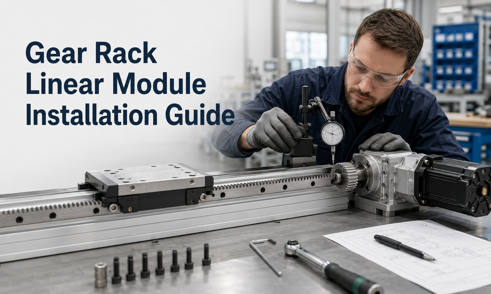
1. Preparation Before Installation
Before assembling the linear module, confirm the installation drawings, rack specifications, pinion parameters, gearbox ratio, motor model and required travel. Different rack modules, tooth profiles and accuracy grades require different mounting and meshing conditions.
Prepare the following tools and inspection equipment:
- Precision level
- Dial indicator and magnetic base
- Straightedge or alignment reference
- Feeler gauges
- Torque wrench
- Vernier caliper or micrometer
- Rack joint alignment tool or matching rack section
- Recommended lubricant and lubrication tools
- Thread-locking compound specified for the fasteners
- Cleaning cloths and non-corrosive cleaning agent
Inspect the rack teeth, pinion, guide rails, carriage, gearbox flange and mounting holes before installation. Components with dents, burrs, corrosion, tooth damage or abnormal deformation should not be installed.
2. Mounting Surface Preparation
The installation base directly affects the straightness, rigidity and running accuracy of the gear rack axis. The mounting surface must be sufficiently rigid to support the module, payload and dynamic forces generated during acceleration and deceleration.
Before mounting the module:
- Remove oil, dust, metal chips, paint residue and burrs from the mounting surface.
- Check the flatness and straightness of the base according to the equipment drawing.
- Confirm that locating shoulders and reference edges are clean and undamaged.
- Inspect threaded holes and positioning holes for dimensional or machining errors.
- Ensure that the base structure does not deform when the mounting bolts are tightened.
Do not use the mounting bolts to force a distorted module against an uneven surface. This can twist the guide rails, increase carriage resistance and cause uneven gear meshing.
3. Installing and Aligning the Linear Guide
The linear guide determines the movement direction of the carriage and should normally be aligned before the rack is finally positioned. The rack must remain parallel to the actual travel path of the carriage rather than only parallel to the edge of the machine base.
Place the guide rail or complete module base on the mounting surface and lightly tighten the bolts. Use the reference shoulder, straightedge or dial indicator to align the master guide. Tighten the bolts gradually from the reference end toward the opposite end.
For systems using two parallel guide rails, install the reference rail first. Then move the carriage along the complete stroke while adjusting the secondary rail. The carriage should move smoothly without binding, local resistance or abnormal variation in preload.
After alignment, tighten all guide and base fasteners to the specified torque. Recheck straightness and running resistance because tightening can slightly change the alignment.
4. Installing the First Rack Segment
The first rack segment establishes the reference for all following segments. Position it against the designed locating surface and confirm the correct tooth direction, installation height and distance from the linear guide.
Initially tighten the rack screws only enough to hold the segment in place. Use a dial indicator or suitable reference tool to check that the rack is parallel to the guide movement. Move the carriage or measurement fixture along the rack and observe the variation over the complete length.
After the rack position is confirmed, tighten the fasteners gradually and evenly. If the design includes locating pins, install them only after the rack has been accurately aligned and the final position has been verified.
5. Rack Segment Alignment
Long-stroke gear rack modules commonly use several rack segments connected end to end. The joint between two segments must maintain the correct tooth pitch. A joint that is too narrow, too wide or vertically offset can produce impact, noise, vibration and positioning errors every time the pinion passes over it.
A common alignment method is to use a short matching rack section placed upside down across the joint. Its teeth engage with both installed rack segments and help maintain the correct tooth pitch during adjustment.
The basic procedure is:
- Secure the first rack segment as the reference.
- Position the next segment close to the reference segment without fully tightening it.
- Place the matching rack section across the joint so that it engages both segments.
- Adjust the second segment until the temporary rack section seats evenly without rocking.
- Check the vertical height and side alignment at the joint.
- Gradually tighten the second rack segment while keeping the joint tool engaged.
- Remove the joint tool and manually inspect the transition between the two segments.
Repeat the process for each additional rack segment. Do not assume that the machine base edge alone can maintain tooth-pitch accuracy across all rack joints.
6. Rack Joint Adjustment
After the rack segments are installed, inspect every joint individually. The tooth transition should be smooth, and the pinion should pass through the joint without impact or sudden resistance.
Check the following conditions:
- The two rack segments are at the same mounting height.
- The tooth pitch remains continuous across the joint.
- There is no lateral offset between adjacent segments.
- The rack ends do not contact each other in a way that causes thermal expansion problems.
- The mounting screws do not pull either rack segment out of alignment.
Slowly roll a test pinion across each joint or move the carriage manually with the drive disconnected. If resistance changes at the joint, loosen the adjacent rack segment and repeat the alignment procedure.
7. Gearbox and Pinion Installation
Install the servo motor, gearbox, coupling and pinion according to the assembly drawing. The gearbox flange and mounting bracket must be clean, flat and rigid. Any angular error in the gearbox installation can cause uneven contact across the pinion tooth width.
Before tightening the gearbox mounting bolts, confirm:
- The pinion axis is perpendicular to the rack travel direction.
- The pinion tooth width is correctly positioned relative to the rack.
- The gearbox output shaft has no abnormal radial or axial play.
- The coupling is installed without excessive axial preload.
- The motor and gearbox fasteners are tightened evenly.
When a spring-loaded or eccentric meshing mechanism is used, inspect its movement range and preload adjustment before engaging the pinion with the rack.
8. Pinion Meshing Adjustment
Correct pinion meshing distributes the load across the tooth surface while allowing smooth movement. Excessive engagement increases friction, heat, noise and tooth wear. Insufficient engagement increases backlash and can cause tooth impact under reversing loads.
Adjust the center distance between the rack and pinion according to the rack and gearbox specifications. Rotate or move the pinion slowly while checking the contact condition along the complete stroke.
Apply a thin layer of marking compound to several rack teeth when necessary. Move the pinion through the marked area and inspect the contact pattern. The contact should be reasonably even across the working tooth width rather than concentrated at one edge.
Check meshing at multiple positions along the axis. A setting that is correct at one end but too tight at the opposite end usually indicates that the rack is not parallel to the guide travel.
9. Backlash Adjustment
Backlash is the relative movement between the rack and pinion when the drive direction reverses. A certain amount of backlash may be required for lubrication, manufacturing tolerance and thermal expansion. However, excessive backlash reduces positioning accuracy and can create impact during acceleration reversal.
To check backlash:
- Lock or hold the carriage so that it cannot move freely.
- Place a dial indicator against the carriage or drive mechanism.
- Apply a small rotational force to the pinion in one direction.
- Reverse the force without moving the rack position significantly.
- Record the lost motion shown by the indicator.
Adjust backlash through the gearbox mounting position, eccentric mechanism, spring preload or other adjustment structure provided by the module design. Always follow the specified range for the particular rack and pinion system.
Do not eliminate backlash by forcing the pinion deeply into the rack. Zero clearance under static conditions can produce tooth interference after temperature changes, lubrication film formation or base deformation.
10. Checking the Complete Stroke
After the rack, pinion and gearbox have been adjusted, move the carriage manually across the full travel with the motor power disconnected. The required force should remain reasonably consistent.
Pay particular attention to:
- Rack joints
- Stroke ends
- Guide rail connection areas
- Cable carrier transition points
- Locations near mounting brackets
If the movement becomes tight at a specific position, inspect rack parallelism, guide alignment, rack height and pinion engagement at that location. Do not proceed to powered operation until the cause has been corrected.
11. Lubrication
Proper lubrication reduces friction, tooth wear, noise and temperature rise. Apply the lubricant recommended for the rack material, operating speed, load and environmental conditions.
Before lubrication, clean the rack teeth and remove dust, chips and old contaminated grease. Apply a uniform film along the working tooth surfaces. Excessive grease can collect abrasive particles, while insufficient lubrication can cause rapid surface wear.
For automatic lubrication systems:
- Confirm the lubricant type and supply pressure.
- Check the tubing and fittings for leakage.
- Verify that lubricant reaches the rack and pinion contact area.
- Set the lubrication interval according to the operating cycle.
- Inspect the lubrication system during initial commissioning.
The linear guide and gearbox may require different lubricants. Do not mix incompatible grease types without approval from the component manufacturer.
12. Sensor and Limit Switch Setup
Install the home sensor, positive limit sensor, negative limit sensor and any additional position switches according to the control design. Sensor brackets must be rigid enough to prevent movement caused by vibration.
Adjust the sensor positions so that the controller receives the stop signal before the carriage reaches the mechanical stroke limit. Mechanical stops should be treated as emergency protection rather than normal stopping positions.
Check the following items:
- Sensor power supply and wiring polarity
- Normally open or normally closed signal configuration
- Trigger distance and detection repeatability
- Cable protection throughout the complete stroke
- Controller input status
- Home return direction and home offset
Move the carriage manually or at very low speed while verifying each sensor signal before normal operation.
13. Motor and Controller Configuration
Enter the correct motor, encoder, gearbox ratio, pinion pitch diameter and motion conversion parameters into the controller. Incorrect electronic gearing can cause the commanded travel distance to differ from the actual movement.
For a rack-and-pinion axis, the theoretical travel per pinion revolution is related to the pinion pitch diameter:
Travel per revolution = π × pinion pitch diameter
The actual motor travel conversion must also include the gearbox ratio and any additional transmission ratio. Confirm all units before entering the parameters into themotion controller.
Set conservative speed, acceleration, deceleration, torque and following-error limits for the first powered test. High-speed parameters should only be applied after the mechanical installation has been verified.
14. Initial Commissioning
Begin commissioning at low speed and without the full production load. Use a short movement command and keep the emergency stop available.
The recommended commissioning sequence is:
- Confirm that all fasteners, covers and cables are secure.
- Verify the motor direction and encoder feedback direction.
- Test the positive and negative limit sensors.
- Perform a low-speed jog near the center of the stroke.
- Move across each rack joint and listen for impact or abnormal noise.
- Run the complete stroke at low speed.
- Perform the home return procedure.
- Gradually increase speed and acceleration.
- Add the operating load and repeat the motion test.
- Check motor current, gearbox temperature, vibration and positioning error.
Stop the system immediately if there is severe vibration, tooth impact, abnormal temperature rise, motor overload or repeated following-error alarms.
15. Positioning and Repeatability Verification
After the axis runs smoothly, verify the positioning performance using a dial indicator, laser measurement system or other suitable inspection equipment.
Measure positions at several points across the stroke and approach each point from both movement directions. This helps identify backlash, rack-joint errors, scale errors and bidirectional positioning differences.
If the mechanical installation is stable but a consistent travel error remains, check the pinion diameter, gearbox ratio and controller conversion parameters. Software compensation should only be applied after mechanical errors have been reduced as much as reasonably possible.
16. Common Installation Problems
| Problem | Possible Cause | Recommended Check |
|---|---|---|
| Impact at rack joints | Incorrect tooth pitch or height difference between segments | Realign the joint using a matching rack section |
| Noise increases along the stroke | Rack is not parallel to the guide | Measure rack-to-guide distance at multiple positions |
| High motor current | Excessive pinion engagement or guide misalignment | Check manual running resistance and backlash |
| Position changes after direction reversal | Excessive backlash or loose transmission components | Inspect rack-pinion clearance, coupling and gearbox output |
| Uneven tooth wear | Pinion angular misalignment or poor lubrication | Check tooth contact pattern and lubricant distribution |
| Repeated limit alarms | Incorrect sensor position or controller travel settings | Verify sensor signals, soft limits and home offset |
| Vibration during acceleration | Loose base, insufficient rigidity or aggressive motion parameters | Check mounting bolts, structure and servo settings |
17. Installation Acceptance Checklist
Before putting the gear rack linear module into production, confirm that:
- The installation base is flat, clean and sufficiently rigid.
- The guide rails are aligned and the carriage moves smoothly.
- All rack segments are parallel to the movement direction.
- Every rack joint has a continuous tooth pitch.
- The pinion contact pattern is even.
- Backlash is within the specified range.
- The gearbox, motor and coupling are securely installed.
- The rack, pinion and guide are correctly lubricated.
- Home and limit sensors operate reliably.
- The controller travel conversion is correct.
- The axis completes the full stroke without abnormal noise or resistance.
- Positioning accuracy and repeatability meet the application requirements.
Conclusion
Installing a gear rack linear module requires coordinated adjustment of the mounting base, linear guide, rack segments, rack joints, pinion, gearbox and control system. The rack should be aligned to the actual carriage movement, and every joint must maintain a continuous tooth pitch. Pinion meshing and backlash should be adjusted across the entire stroke rather than at only one position.
Careful lubrication, sensor setup and low-speed commissioning help prevent premature wear and identify installation errors before full-load operation. A properly installed gear rack linear module can provide reliable high-speed, heavy-load and long-stroke motion forgantry robots, material handling systems, machine tools and industrial automation equipment.
