 English

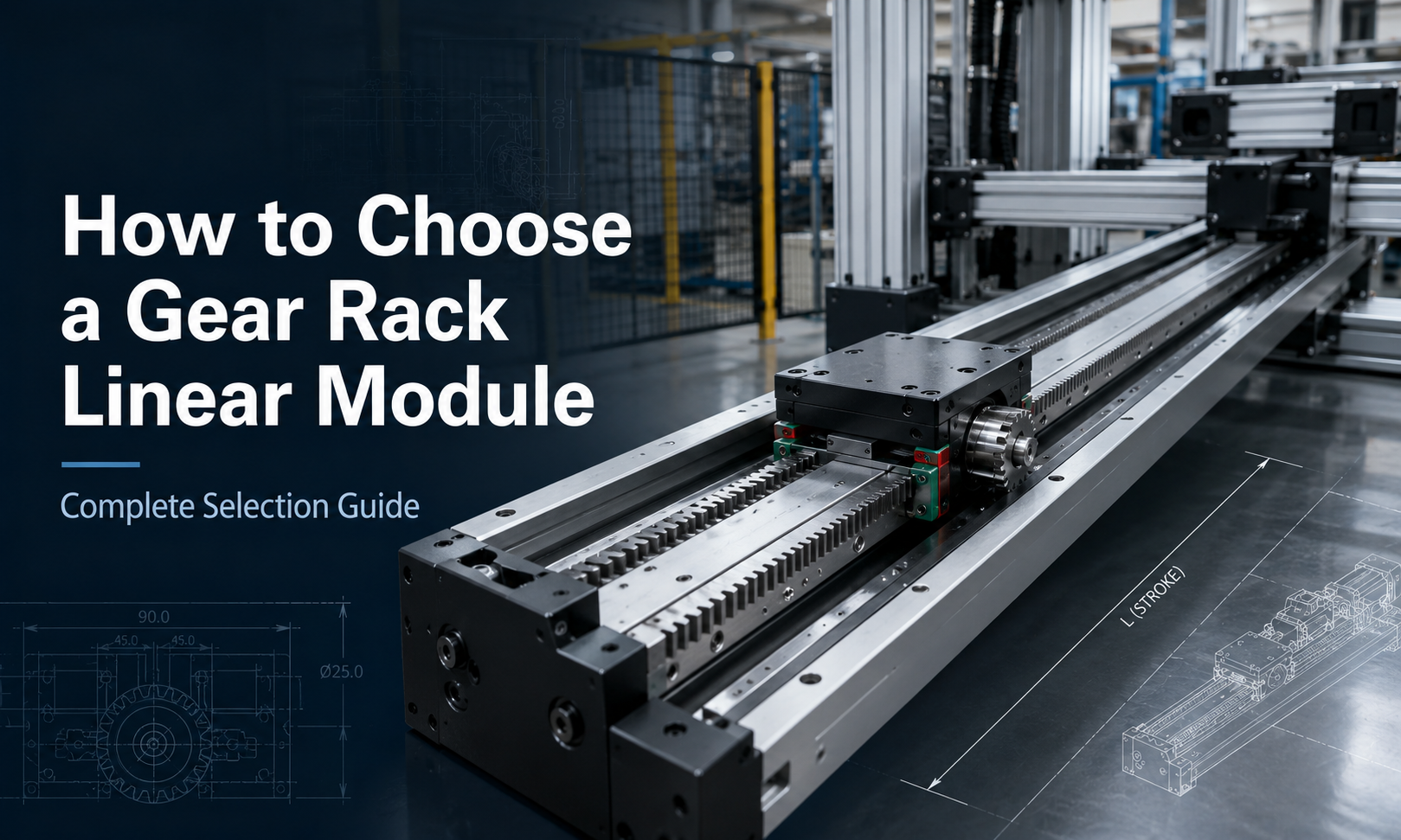
A gear racklinear moduleis commonly used in long-stroke, high-speed and heavy-load automation systems. Unlike a ball screw system, whose maximum travel length can be limited by screw deflection and critical speed, a rack and pinion drive can be extended by connecting multiple rack sections. This makes it suitable forgantry robots, machine tending, material handling, laser cutting, welding, palletizing and warehouse automation.
However, selecting a gear rack linear module requires more than checking its nominal payload. Load direction, stroke, speed, acceleration, positioning accuracy, rack module, gear ratio, motor torque, installation orientation and environmental conditions must all be evaluated together.
This guide explains how to choose a gear rack linear module systematically and how to avoid common sizing mistakes.
1. Define the Application Requirements
The selection process should begin with a clear description of the application. Before comparing product specifications, collect the following information:
- Type of machine or automation system
- Required payload
- Total moving mass
- Effective travel stroke
- Maximum linear speed
- Acceleration and deceleration
- Required cycle time
- Positioning accuracy
- Repeatability requirement
- Installation orientation
- Expected operating hours
- Environmental conditions
- Available motor and gearbox space
It is important to distinguish between payload and total moving mass. The motor must accelerate not only the workpiece, but also the carriage, tooling, gripper, brackets, cables and any components mounted on the moving platform.
The basic moving mass can be expressed as:
Total moving mass = Payload + Carriage-mounted tooling + Fixtures + Cable system + Other moving components
Using only the payload in the calculation may result in an undersized motor, gearbox or pinion.
2. Determine the Required Load Capacity
Gear rack linear module load capacity is affected by the linear guide, carriage dimensions, bearing arrangement, aluminum or steel base, rack size and installation direction.
The main load types include:
- Vertical load acting directly on the carriage
- Horizontal load during side-mounted installation
- Axial driving force along the motion direction
- Pitching moment caused by an offset load
- Yawing moment caused by lateral offset
- Rolling moment around the travel axis
- Dynamic load generated by acceleration and deceleration
Static Load
Static load is the force applied when the module is stationary or moving at a constant low speed. For horizontal installation, the main vertical load is approximately:
Fstatic= m × g
Where:
Fstaticis the static load in newtonsmis the total supported mass in kilogramsgis gravitational acceleration, approximately 9.81 m/s²
Acceleration Force
The force required to accelerate the moving mass is:
Facc= m × a
Whereais the required acceleration in m/s².
For a horizontal axis, the estimated driving force can be expressed as:
Fdrive= m × a + Ffriction+ Fexternal
For a vertical axis, gravity must also be included:
Fdrive= m × a + m × g + Ffriction+ Fexternal
Vertical gear rack axes normally require a brake motor, counterbalance device or mechanical anti-fall mechanism.
Moment Load
An offset load creates a moment on the carriage and guide system:
M = F × L
Where:
Mis the moment loadFis the applied forceLis the distance from the force to the carriage center
A module may have sufficient nominal payload but still be unsuitable if the tooling extends too far from the carriage. Always compare the calculated pitching, yawing and rolling moments with the allowable moment values supplied by the manufacturer.
3. Confirm the Required Stroke
Stroke is one of the main reasons for selecting a rack and pinion actuator. Rack-driven systems can support long travel by joining rack sections along the module base.
The required effective stroke should include:
- Normal working travel
- Tool approach and withdrawal distance
- Loading and unloading clearance
- Sensor and limit-switch margin
- Deceleration distance
- Maintenance or service position
The recommended axis length can be estimated as:
Total module length = Effective stroke + Carriage length + End clearances
For long-stroke systems, also evaluate:
- Base straightness over the full length
- Rack joint alignment
- Guide rail joint accuracy
- Support spacing
- Thermal expansion
- Cable carrier length
- Installation and transportation limits
Long travel does not automatically mean unlimited unsupported length. The supporting machine frame must provide sufficient rigidity and installation accuracy.
4. Calculate Speed, Acceleration and Cycle Time
Maximum speed should not be selected independently from acceleration and cycle time. A machine may have a high nominal speed but still fail to achieve the required cycle time if acceleration is too low or the travel distance is short.
For a triangular motion profile, where the axis accelerates and then immediately decelerates, the peak speed is:
vpeak= √(a × S)
Where:
vpeakis peak speedais accelerationSis travel distance
For a trapezoidal motion profile, total travel time can be estimated as:
ttotal= tacc+ tconstant+ tdec
The complete cycle time should also include:
- Motion time
- Tool operating time
- Clamping or gripping time
- Sensor confirmation time
- Controller delay
- Loading and unloading time
Do not select the motor based only on maximum speed. The motor must also provide sufficient peak torque during acceleration and sufficient continuous torque for repetitive operation.
5. Select the Rack Module
The rack module describes the size of the gear teeth. A larger rack module generally provides larger teeth, higher tooth strength and greater allowable tangential force. However, it also increases pinion size, transmission dimensions and potentially positioning resolution per motor revolution.
The relationship between module, pitch diameter and number of pinion teeth is:
d = m × z
Where:
dis the pinion pitch diametermis the rack modulezis the number of pinion teeth
The linear travel produced by one pinion revolution is approximately:
L = π × d = π × m × z
A larger module is generally considered when the system requires:
- Higher driving force
- Heavy payload
- High acceleration
- Frequent start-stop operation
- High shock-load resistance
- Long industrial service life
A smaller module may be suitable for lighter loads, compact systems and applications requiring finer transmission resolution.
| Selection Condition | Rack Module Tendency | Main Reason |
|---|---|---|
| Light load and compact machine | Smaller module | Reduced size and inertia |
| Heavy load and high thrust | Larger module | Higher tooth strength |
| High acceleration | Medium or larger module | Greater dynamic load capacity |
| Shock or impact loading | Larger module | Improved tooth durability |
| High positioning resolution | Smaller module or higher gear reduction | Less travel per motor revolution |
The final rack module should be confirmed using the manufacturer’s allowable tangential force, tooth contact stress, lubrication method and expected duty cycle.
6. Choose the Pinion Diameter
Pinion diameter directly affects linear speed, output force and positioning resolution.
A larger pinion produces more linear travel per revolution and can increase maximum axis speed. However, for the same output torque, a larger pitch radius reduces the available tangential force.
The relationship between output torque and linear driving force is:
F = T / r
Where:
Fis tangential driving forceTis pinion output torqueris pinion pitch radius
A smaller pinion provides more driving force for the same torque and improves linear resolution, but it may limit maximum speed and increase motor revolutions.
Pinions with too few teeth may also have unfavorable tooth engagement or increased wear. The selected pinion should match the rack specifications and the manufacturer’s minimum tooth-number requirements.
7. Select the Gear Ratio
A gearbox is commonly installed between the servo motor and pinion. The gear ratio affects output torque, axis speed, reflected inertia and positioning resolution.
The approximate gearbox output torque is:
Tout= Tmotor× i × n
Where:
Toutis gearbox output torqueTmotoris motor torqueiis the reduction ratiooris gearbox efficiency
The gearbox output speed is:
nout= nmotor/ i
A higher reduction ratio provides:
- Higher output torque
- Lower pinion speed
- Improved motor-to-load inertia matching
- Finer theoretical positioning resolution
However, an excessively high ratio may reduce maximum linear speed and increase cycle time.
A lower reduction ratio provides:
- Higher axis speed
- Lower gearbox multiplication
- Lower motor revolutions for a given movement
But it requires the motor to provide more torque directly.
The correct gear ratio should satisfy both speed and torque requirements:
Required output speed ≤ Allowable gearbox output speed
Required output torque × Safety factor ≤ Allowable gearbox torque
8. Evaluate Positioning Accuracy and Repeatability
Positioning accuracy and repeatability are different specifications.
- Positioning accuracyindicates how close the actual position is to the commanded position over the full stroke.
- Repeatabilityindicates how consistently the axis returns to the same position under the same conditions.
The total positioning error of a gear rack linear module may be affected by:
- Rack pitch error
- Rack joint alignment
- Pinion manufacturing accuracy
- Gearbox backlash
- Rack and pinion backlash
- Guide rail straightness
- Base installation error
- Servo tuning
- Encoder resolution
- Structural deflection
- Temperature variation
For applications such as welding, material transfer and palletizing, repeatability may be more important than absolute accuracy. For precision machining, measurement or laser processing, full-stroke positioning accuracy may require higher-grade racks, low-backlash gearboxes, encoder feedback or compensation calibration.
Backlash Control Methods
Backlash can be reduced by using:
- Precision-ground or high-accuracy racks
- Low-backlash planetary gearboxes
- Adjustable rack and pinion engagement
- Preloaded dual-pinion systems
- Proper bearing support
- Accurate servo tuning
- Linear encoder closed-loop feedback
Zero backlash should not be assumed unless the complete drive system has been designed and verified for that performance.
9. Consider the Installation Orientation
Installation orientation affects guide loading, motor torque, lubrication and safety requirements.
| Orientation | Main Considerations |
|---|---|
| Horizontal, carriage facing upward | Standard load arrangement, relatively simple lubrication and cable routing |
| Horizontal, side-mounted | Higher rolling moment and uneven guide loading may occur |
| Inverted installation | Fastener security, lubrication retention and falling-object protection |
| Vertical installation | Gravity load, brake motor, anti-fall design and emergency stopping |
| Inclined installation | Gravity component must be included in thrust calculations |
For an inclined axis, the gravitational force acting along the travel direction can be estimated as:
Fgravity= m × g × sin θ
Whereiis the inclination angle.
10. Select the Servo Motor
The servo motor must satisfy speed, continuous torque, peak torque, inertia matching and duty-cycle requirements.
Motor Speed
The required motor speed can be estimated from the required linear velocity:
nmotor= (v × 60 × i) / (π × d)
Where:
nmotoris motor speed in rpmvis linear velocity in m/siis the gearbox reduction ratiodis pinion pitch diameter in meters
Motor Torque
The required pinion torque is approximately:
Tpinion= Fdrive× r
The required motor torque is:
Tmotor= Tpinion/ (i × n)
Additional torque should be included for:
- Gearbox inertia
- Pinion inertia
- Coupling losses
- Guide friction
- Cable carrier resistance
- External machining or process forces
Peak motor torque must cover acceleration and emergency conditions, while continuous torque must remain within the motor’s rated thermal capacity during repeated cycles.
Inertia Matching
Excessive load-to-motor inertia ratio can make servo tuning difficult and reduce dynamic response. A gearbox can improve inertia matching because reflected load inertia decreases approximately with the square of the reduction ratio:
Jreflected= Jload/ i²
The acceptable inertia ratio depends on the servo system, gearbox, control requirements and motion profile.
11. Select the Gearbox
Planetary gearboxes are widely used with gear rack axes because they provide compact dimensions, high torque density and relatively low backlash.
When choosing a gearbox, check:
- Nominal output torque
- Maximum acceleration torque
- Emergency-stop torque
- Permitted radial and axial loads
- Maximum input and output speed
- Backlash
- Torsional rigidity
- Efficiency
- Service life
- Lubrication and mounting orientation
The gearbox output bearing may not be designed to support all radial forces generated by the pinion. In heavy-duty systems, an independent pinion bearing arrangement may be required.
12. Check the Structural Rigidity
A gear rack module can generate sufficient thrust but still fail to maintain accuracy if the base, carriage, mounting frame or machine structure deflects under load.
Structural rigidity should be evaluated for:
- Module base bending
- Carriage plate deformation
- Guide rail deflection
- Support-frame vibration
- Crossbeam bending in gantry systems
- Tooling overhang
- Dynamic resonance
For a gantry robot, the beam span, moving load and acceleration must be considered together. Increasing acceleration may significantly increase beam deflection and vibration even when the static payload remains unchanged.
13. Evaluate the Operating Environment
Environmental conditions affect rack lubrication, sealing, corrosion resistance and component life.
| Environment | Recommended Considerations |
|---|---|
| Dust and particles | Protective cover, bellows, scraper, sealed guide blocks and frequent cleaning |
| Metal chips | Steel cover, chip guard and protected rack orientation |
| Coolant or oil mist | Corrosion-resistant materials and compatible seals |
| High humidity | Anti-corrosion treatment and moisture-resistant lubrication |
| High temperature | Thermal expansion analysis and high-temperature lubricant |
| Low temperature | Low-temperature grease and suitable cable materials |
| Clean environment | Low-particle lubrication and enclosed drive components |
| Washdown environment | Special sealing, drainage and corrosion protection |
Open rack drives require regular lubrication. If dust or abrasive particles mix with the lubricant, tooth wear can accelerate. Protective design should therefore be considered at the beginning of the selection process.
14. Apply an Appropriate Safety Factor
A safety factor compensates for uncertainties such as load variation, impact, calculation error, friction changes and future process adjustments.
The design force can be calculated as:
Fdesign= Fcalculated× S
WhereSis the selected safety factor.
| Operating Condition | Typical Safety-Factor Approach |
|---|---|
| Smooth, predictable load | Lower safety margin may be acceptable |
| Frequent acceleration and deceleration | Moderate safety margin |
| Shock, vibration or uncertain load | Higher safety margin |
| Vertical lifting | Higher safety margin plus anti-fall protection |
| Continuous industrial production | Margin for thermal load and service life |
The safety factor should not be applied only to motor torque. Rack teeth, pinion, gearbox, guide rails, bearings, carriage, mounting bolts and supporting frame must all be checked.
15. Gear Rack Linear Module Selection Example
Consider a horizontal material-handling axis with the following requirements:
- Payload: 120 kg
- Moving tooling and carriage-mounted components: 40 kg
- Total moving mass: 160 kg
- Effective stroke: 6 m
- Maximum speed: 2 m/s
- Acceleration: 3 m/s²
- External resistance and friction: 150 N
- Selected safety factor: 1.5
Step 1: Calculate Acceleration Force
Facc= 160 × 3 = 480 N
Step 2: Add Friction and External Resistance
Fcalculated= 480 + 150 = 630 N
Step 3: Apply the Safety Factor
Fdesign= 630 × 1.5 = 945 N
Step 4: Estimate Pinion Torque
If the pinion pitch radius is 40 mm, or 0.04 m:
Tpinion= 945 × 0.04 = 37.8 N·m
Step 5: Estimate Motor Torque
If a 10:1 gearbox with 90% efficiency is used:
Tmotor= 37.8 / (10 × 0.9) = 4.2 N·m
The selected motor must provide more than 4.2 N·m under the required acceleration conditions. Continuous torque, peak torque, inertia ratio and duty cycle must then be checked separately.
Step 6: Check Motor Speed
For a pinion pitch diameter of 80 mm:
nmotor= (2 × 60 × 10) / (π × 0.08) ≈ 4,775 rpm
If the chosen servo motor cannot operate continuously at this speed, the pinion diameter, gearbox ratio or target speed must be adjusted.
This example shows why torque and speed must be checked together. A higher gear ratio increases torque but also increases the required motor speed for the same linear velocity.
16. Common Selection Mistakes
Using Payload Instead of Total Moving Mass
Ignoring tooling, fixtures, carriage-mounted components and cable carriers leads to underestimated acceleration force.
Selecting Only by Nominal Load Capacity
Nominal payload does not guarantee sufficient moment capacity, dynamic rigidity or service life.
Ignoring Gearbox Backlash
A high-accuracy rack cannot compensate for excessive gearbox backlash.
Choosing an Excessively Large Pinion
A large pinion increases linear travel per revolution but reduces tangential force for the same output torque.
Choosing the Gear Ratio Based Only on Torque
An overly high reduction ratio may make the required motor speed exceed its allowable operating range.
Ignoring Rack Joint Accuracy
Poor alignment between rack sections can cause vibration, noise, tooth impact and positioning error.
Ignoring the Supporting Frame
A rigid linear module mounted on a flexible frame cannot maintain its specified accuracy.
Insufficient Lubrication Planning
Improper lubrication can cause tooth wear, increased noise, temperature rise and shortened service life.
17. Gear Rack Linear Module Selection Checklist
| Selection Item | Required Information |
|---|---|
| Application | Machine type, process and operating sequence |
| Load | Payload, tooling mass, external force and offset distance |
| Stroke | Effective travel, clearance and maintenance position |
| Motion | Speed, acceleration, deceleration and cycle time |
| Accuracy | Positioning accuracy, repeatability and backlash |
| Rack and pinion | Module, tooth grade, pinion diameter and lubrication |
| Gearbox | Ratio, torque, speed, backlash and radial-load capacity |
| Motor | Rated torque, peak torque, maximum speed and inertia |
| Installation | Horizontal, vertical, side-mounted, inverted or inclined |
| Environment | Dust, chips, moisture, temperature and corrosion |
| Structure | Base rigidity, support spacing and mounting accuracy |
| Safety | Safety factor, brake, limit switches and anti-fall design |
Frequently Asked Questions
When should a gear rack linear module be selected instead of a ball screw module?
A gear rack module is generally preferred for long strokes, high speeds, heavy loads and applications where the axis length must be extended by connecting multiple sections. Aball screw modulemay be more suitable for shorter strokes and applications requiring high precision with compact transmission components.
Does a larger rack module always provide better performance?
No. A larger module increases tooth strength and load capacity, but it also increases size, inertia and travel per pinion revolution. The module should match the required force, speed, accuracy and duty cycle.
How should the gearbox ratio be selected?
The ratio must allow the motor to meet both torque and speed requirements. A higher ratio increases output torque and improves inertia matching, but it also reduces pinion speed and may increase the required motor speed for a given linear velocity.
Can a gear rack linear module be installed vertically?
Yes, but the motor must continuously overcome gravity, and the system should normally include a brake motor, mechanical anti-fall device or counterbalance mechanism. Vertical holding and emergency-stop conditions must be calculated separately.
What determines the positioning accuracy of a rack-driven axis?
Positioning accuracy depends on rack pitch accuracy, rack joint alignment, pinion quality, gearbox backlash, guide straightness, machine-frame rigidity, servo tuning, encoder feedback and temperature variation.
How much safety factor should be used?
The appropriate safety factor depends on load stability, acceleration, shock, installation direction, operating hours and the consequences of failure. Smooth horizontal systems may use a lower margin, while vertical, impact-loaded or continuous-duty systems generally require a higher margin.
Conclusion
Choosing a gear rack linear module requires a complete evaluation of the mechanical load, motion profile, rack and pinion geometry, gearbox, servo motor, positioning requirements, installation direction and operating environment.
The most important steps are to calculate the total moving mass, determine the required driving force, verify moment loads, select a suitable rack module and pinion diameter, balance gearbox torque against motor speed, and confirm the rigidity of the complete machine structure.
A properly selected rack and pinion actuator provides scalable stroke, high speed, strong load capacity and reliable operation for long-distance industrial automation. For demanding applications, the final selection should be verified using the actual motion profile, duty cycle, structural layout and manufacturer-specific load data.
