 English

Gear rack linear modules are widely used in long-stroke, high-speed and heavy-load automation systems. Their transmission structure is durable, but positioning errors, excessive backlash, abnormal noise, vibration, tooth wear and gearbox overheating may develop when installation, lubrication or operating conditions are unsuitable.
Effective troubleshooting should follow a systematic process rather than replacing components immediately. Operators should first identify the operating condition in which the problem occurs, inspect the mechanical transmission, verify lubrication and alignment, and then check the motor, gearbox, sensors and control parameters.
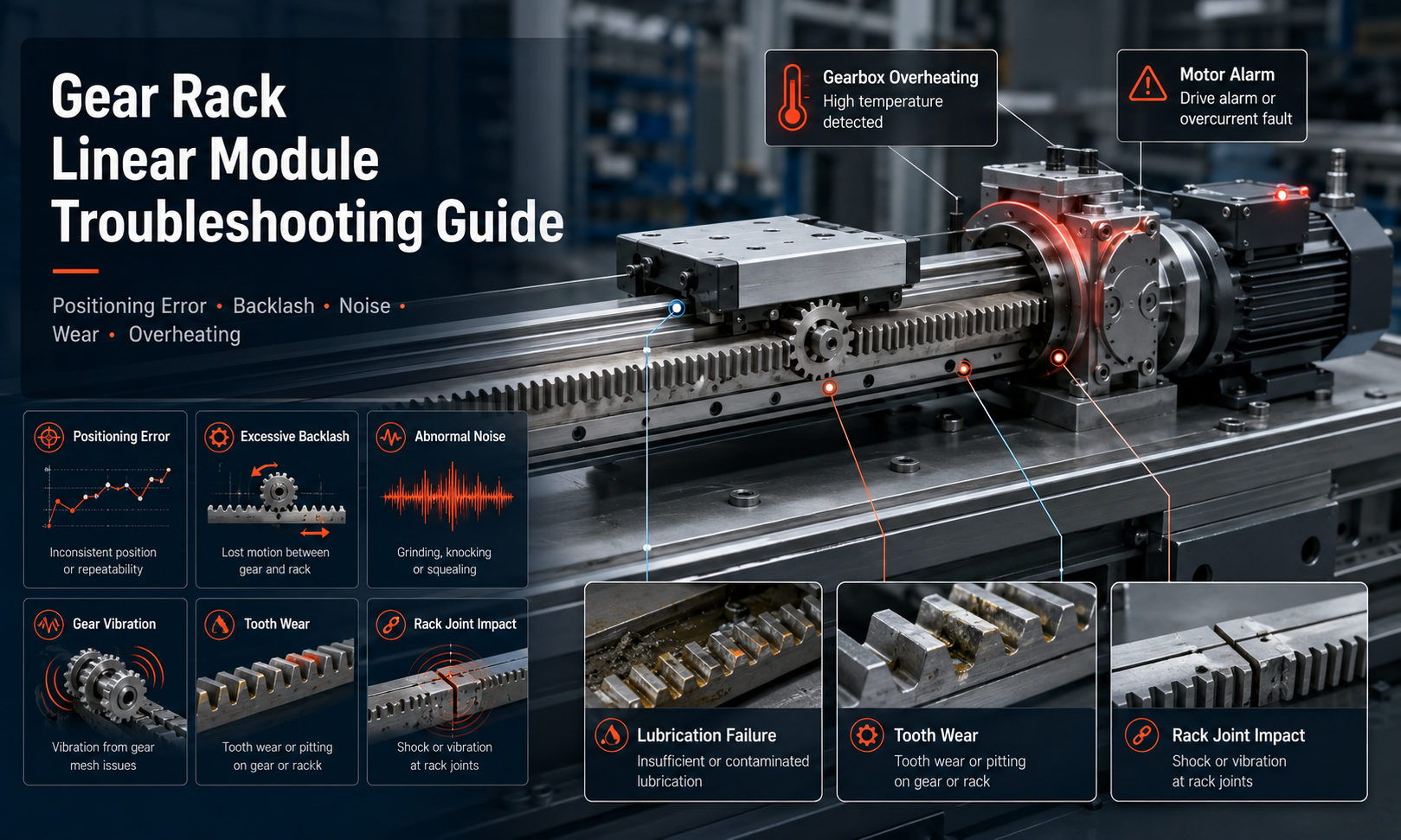
Common Gear Rack Linear Module Problems
| Problem | Possible Causes | Recommended Checks |
|---|---|---|
| Positioning error | Backlash, loose fasteners, incorrect calibration, rack misalignment or encoder problems | Check repeatability, rack alignment, pinion engagement, coupling and control settings |
| Excessive backlash | Incorrect meshing clearance, tooth wear, loose gearbox or worn bearings | Measure backlash and inspect the rack, pinion, reducer and mounting structure |
| Abnormal noise | Insufficient lubrication, poor meshing, contamination, damaged teeth or bearing wear | Locate the noise source and inspect lubrication, tooth contact and rotating components |
| Gear vibration | Rack misalignment, unstable mounting, excessive acceleration or damaged bearings | Check installation rigidity, rack straightness, guide alignment and motion parameters |
| Tooth wear | Overload, poor lubrication, contamination or incorrect pinion engagement | Inspect the tooth contact pattern, lubricant condition and operating load |
| Rack joint impact | Segment height difference, incorrect tooth pitch alignment or loose rack sections | Inspect rack joints with a reference pinion and verify joint flatness |
| Gearbox overheating | Overload, excessive preload, poor lubrication or incorrect motor parameters | Measure temperature, load, operating current and gearbox condition |
| Engine alarm | Overload, mechanical jamming, incorrect parameters, cable faults or sensor problems | Read the alarm code and separate mechanical causes from electrical causes |
Safety Preparations Before Troubleshooting
Before inspecting a gear racklinear module, stop the equipment and isolate all power sources. Apply the required lockout and tagout procedure, release stored pneumatic or mechanical energy, and support any vertically mounted or suspended load.
Do not place hands near the rack, pinion, guide rail or carriage while the axis is moving. Manual inspection should only be carried out after the drive system has been disabled and accidental startup has been prevented.
Prepare the maintenance record, alarm history, operating parameters and recent production changes. Information about when the fault started is often as important as the visible condition of the module.
1. Positioning Error
Positioning error may appear as an incorrect stopping position, inconsistent travel distance or a difference between the commanded position and the actual position. The first step is to determine whether the error is repeatable.
If the axis repeatedly stops at the same incorrect position, the problem may be related to calibration, transmission ratio, encoder scaling, home offset or control parameters. If the error changes between cycles, mechanical looseness, backlash, rack contamination, unstable loading or sensor interference is more likely.
Possible Causes
- Incorrect rack and pinion backlash
- Loose motor, gearbox, rack or carriage fasteners
- Rack sections installed out of alignment
- Worn pinion teeth, rack teeth or gearbox components
- Loose coupling or damaged key connection
- Incorrect encoder resolution or electronic gear ratio
- Home sensor movement or unstable sensor signal
- Excessive load, acceleration or structural deformation
Recommended Checks
- Run the axis repeatedly to the same position and measure repeatability.
- Inspect all mounting bolts and mechanical connections.
- Measure backlash at several positions along the rack.
- Check whether the error increases in one travel direction.
- Inspect the rack joints and tooth contact pattern.
- Verify encoder scaling, transmission ratio and home offset.
- Compare positioning performance under loaded and unloaded conditions.
A gradual increase in positioning error often indicates wear, loosening or lubrication deterioration. A sudden change is more likely to be caused by an impact, parameter modification, loose component or sensor displacement.
2. Excessive Backlash
Backlash is the lost motion that occurs when the travel direction reverses. A small amount of backlash may be required for smooth gear engagement, but excessive clearance reduces positioning accuracy and may cause impact during direction changes.
Possible Causes
- Pinion engagement depth is insufficient
- Rack and pinion teeth are worn
- Gearbox output shaft has excessive play
- Motor coupling or shaft connection is loose
- Gearbox mounting plate has shifted
- Support bearings are worn or damaged
- Preload mechanism has lost adjustment
Troubleshooting Method
Lock the motor shaft or gearbox input and apply a small reversing force to the carriage. Measure the movement before the pinion begins transmitting torque in the opposite direction. Repeat the measurement at several rack positions.
If backlash varies significantly along the stroke, inspect rack straightness, rack mounting height and individual rack sections. If backlash is similar throughout the stroke, the problem may be concentrated in the gearbox, pinion, coupling or adjustment mechanism.
Do not eliminate all clearance by forcing the pinion too tightly against the rack. Excessive preload can increase noise, heat, tooth wear and motor load.
3. Abnormal Noise
Normal rack and pinion drives produce a regular meshing sound. Grinding, knocking, clicking, squealing or irregular impact noise usually indicates a mechanical or lubrication problem.
Noise Characteristics and Likely Causes
| Noise Type | Likely Cause |
|---|---|
| Regular clicking at fixed intervals | Damaged tooth, rack joint error or foreign material on the rack |
| Continuous grinding | Insufficient lubrication, contamination or excessive engagement preload |
| Knocking during reversal | Excessive backlash, loose gearbox or loose coupling |
| High-pitched sound at high speed | Poor alignment, high preload, bearing wear or unsuitable motion parameters |
| Irregular metallic impact | Loose fastener, damaged tooth or contact with an external component |
Operate the module at a low speed and identify where the noise occurs. Determine whether the noise is linked to a specific rack position, travel direction, speed range or load condition. A noise that always occurs at the same position usually points to a local rack, joint or tooth problem.
4. Gear Vibration
Gear vibration can reduce positioning stability, damage tooth surfaces and shorten the service life of the gearbox and guide system. It may be caused by both mechanical installation errors and unsuitable motion-control settings.
Mechanical Causes
- Rack mounting surface is uneven
- Rack is not parallel to the guide rail
- Rack joint is misaligned
- Pinion shaft or gearbox bearing is worn
- Machine frame has insufficient rigidity
- Carriage or load mounting plate is loose
- Guide rail preload is inconsistent
Control-Related Causes
- Acceleration and deceleration are too aggressive
- Servo gain is too high
- Mechanical resonance is not filtered correctly
- Load inertia ratio is unsuitable
- Motion profile produces sudden torque changes
Inspect the mechanical system before changing servo parameters. Tuning the controller cannot permanently correct loose fasteners, damaged bearings or incorrect rack alignment.
5. Tooth Wear
Gear rack tooth wear normally develops gradually. Uniform polishing on the working tooth surfaces may be acceptable, but pitting, scoring, sharp edges, uneven wear or broken teeth require immediate investigation.
Common Causes of Tooth Wear
- Insufficient or unsuitable lubricant
- Metal particles, dust or cutting fluid contamination
- Repeated overload or impact loading
- Incorrect rack and pinion alignment
- Excessive meshing preload
- Incorrect material or hardness combination
- Pinion repeatedly operating on a limited rack area
Inspect several sections of the rack rather than only the most accessible area. Uneven wear on one side of the tooth may indicate angular misalignment. Severe wear concentrated near rack joints may indicate an installation height difference or pitch alignment error.
When replacing a severely worn pinion, inspect the corresponding rack teeth. Installing a new pinion against a heavily worn rack may produce poor contact and accelerate wear of the replacement component.
6. Rack Joint Impact
Long-stroke systems often use multiple rack segments. If the segments are not aligned correctly, the pinion may produce a click, shock or vibration whenever it crosses a joint.
Possible Causes
- Rack segment ends are installed at different heights
- Tooth pitch is not continuous across the joint
- Joint gap is too large or too small
- Mounting screws near the joint are loose
- Rack mounting surface contains burrs or debris
- Rack sections have shifted after an impact
Inspection Method
Move a reference pinion slowly across the joint and observe whether the tooth engagement remains smooth. Check the joint with a dial indicator and verify that both rack sections have consistent height, straightness and pitch alignment.
Do not grind the tooth surfaces as the first corrective action. First confirm the mounting surface, joint position and segment alignment. Uncontrolled grinding can change the tooth profile and weaken the rack.
7. Gearbox Overheating
A gearbox will normally become warm during operation, especially under high load or continuous duty. However, rapidly rising temperature, excessive surface temperature, lubricant leakage or a burning smell may indicate a fault.
Possible Causes
- Operating load exceeds the gearbox rating
- Acceleration or duty cycle is too high
- Rack and pinion preload is excessive
- Gearbox lubricant is insufficient or deteriorated
- Input speed is outside the recommended range
- Bearings or internal gears are damaged
- Motor brake is not releasing completely
- Gearbox mounting alignment is incorrect
Record the gearbox temperature from startup to steady operation. Compare the temperature with motor current, speed, load and cycle time. If the temperature rises when the pinion is disengaged from the rack, the gearbox or motor may be the primary source. If the temperature falls significantly, inspect rack alignment and meshing preload.
8. Engine Alarm
A motor alarm does not always mean the motor is defective. Overload, overcurrent, position deviation and encoder alarms may be triggered by resistance within the mechanical transmission.
Mechanical Conditions That Can Trigger Alarms
- Rack or guide rail contamination
- Pinion engagement is too tight
- Damaged tooth blocks the movement
- Gearbox or bearing is seized
- Load exceeds the designed capacity
- Carriage collides with a mechanical stop
- Cable carrier restricts movement
- Vertical load brake or counterbalance fails
Read and record the exact alarm code before resetting the drive. Check whether the alarm occurs during acceleration, constant-speed travel, deceleration, reversal or stopping. This operating point can help identify whether the cause is overload, tuning, wiring, feedback or mechanical resistance.
9. Lubrication Failure
Lubrication failure can cause noise, rising friction, tooth wear, vibration and overheating. Both insufficient lubrication and excessive lubrication can create problems.
Signs of Insufficient Lubrication
- Dry or discolored tooth surfaces
- Increasing meshing noise
- Metallic particles near the rack
- Rapid temperature increase
- Scoring or pitting on tooth surfaces
Signs of Excessive or Incorrect Lubrication
- Large quantities of grease thrown from the rack
- Dust and debris accumulating in thick grease
- Increased resistance in cold conditions
- Seal damage or lubricant leakage
- Incompatibility between different lubricant types
Clean contaminated lubricant before applying fresh grease. Use a lubricant compatible with the rack material, operating speed, temperature, load and environmental conditions. Follow the equipment manufacturer's lubrication quantity and interval rather than filling the tooth space completely.
Systematic Troubleshooting Workflow
- Record the symptom:Identify the noise, error, vibration, temperature or alarm condition.
- Determine when it occurs:Check the position, direction, speed, load and production cycle.
- Review recent changes:Look for impacts, maintenance, parameter changes, load changes or lubrication work.
- Perform a visual inspection:Check fasteners, rack joints, tooth condition, contamination and lubricant distribution.
- Run at low speed:Locate the problem without exposing personnel to unnecessary risk.
- Separate mechanical and electrical causes:Verify whether resistance exists when the drive is disabled.
- Measure before adjusting:Record backlash, alignment, temperature, motor current and positioning results.
- Correct one factor at a time:Avoid changing multiple mechanical and control settings simultaneously.
- Verify under actual load:Test repeatability, noise, temperature and alarm status during normal operation.
- Document the repair:Record the cause, action, replaced parts and final measurement results.
Preventive Measures
- Inspect rack cleanliness and lubrication regularly.
- Check rack joints and mounting bolts after impacts or heavy-load operation.
- Measure backlash at scheduled maintenance intervals.
- Monitor gearbox temperature and motor current trends.
- Protect the rack from chips, dust, liquids and welding spatter.
- Avoid exceeding the rated load, speed, acceleration and duty cycle.
- Maintain correct alignment between the rack, guide rail, gearbox and pinion.
- Record positioning accuracy and repeatability to identify gradual deterioration.
When Should Components Be Replaced?
Replacement should be considered when tooth damage cannot be corrected by alignment or lubrication, backlash exceeds the allowable value, bearings produce persistent vibration, the gearbox shows abnormal internal play, or positioning performance cannot be restored through adjustment.
Rack, pinion and gearbox components should be evaluated as a complete transmission system. Replacing only one severely worn component may not solve the problem if the mating parts are also damaged.
Conclusion
Gear rack linear module troubleshooting requires a structured inspection of the rack, pinion, gearbox, guide system, motor, sensors and control parameters. Positioning errors, excessive backlash, abnormal noise, vibration and overheating are often connected, so the visible symptom may not be the original cause.
By recording operating conditions, measuring mechanical clearance, checking alignment and lubrication, and separating mechanical faults from electrical faults, maintenance teams can identify problems more accurately and reduce unnecessary component replacement. Regular inspection and preventive maintenance also help preserve positioning performance and extend the service life of the complete gear rack drive system.
