 English

Ball screw linear modulesare widely used in precision automation equipment because they provide accurate positioning, high rigidity, smooth motion and reliable thrust transmission. However, dust, insufficient lubrication, loose fasteners and long-term mechanical wear can gradually reduce positioning accuracy and shorten the service life of the module.
Proper ball screw linear module maintenance should include routine inspection, regular cleaning, correct lubrication and scheduled checks of the coupling, bearings, fasteners and sensors. A structured preventive maintenance program helps identify small problems before they lead to abnormal noise, excessive backlash, motor alarms or unexpected production downtime.
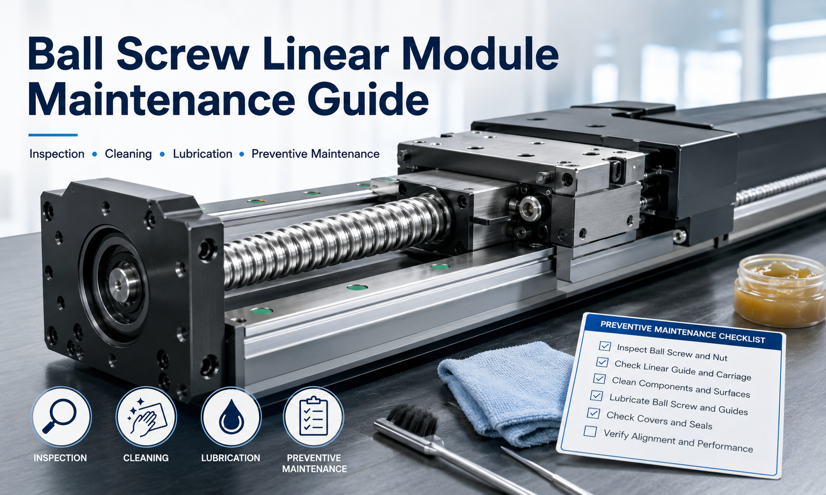
Why Ball Screw Linear Module Maintenance Is Important
A ball screw linear module contains several precision components working together, including the ball screw, ball nut, linear guide, slider, support bearings, coupling, motor mount and position sensors. Contamination or wear in any of these components can affect the complete motion system.
Regular maintenance provides several practical benefits:
- Maintains positioning accuracy and repeatability
- Reduces friction between the ball screw, ball nut and guide components
- Prevents premature wear and corrosion
- Reduces vibration and abnormal operating noise
- Helps avoid coupling and bearing failures
- Improves production stability and equipment availability
- Extends the service life of the linear module
Maintenance requirements depend on operating speed, load, stroke, duty cycle, installation orientation and environmental conditions. Modules operating continuously in dusty, humid or contaminated environments normally require more frequent inspection and lubrication.
Safety Precautions Before Maintenance
Before inspecting or servicing a ball screw linear module, stop the machine and isolate all power sources. The motor must not be able to start unexpectedly while technicians are working near the moving carriage.
- Turn off the main electrical power and servo drive.
- Release stored pneumatic or hydraulic pressure where applicable.
- Apply lockout and tagout procedures according to the machine safety requirements.
- Support the moving carriage before servicing a vertically installed module.
- Allow hot motors, bearings and mechanical components to cool.
- Use clean gloves to prevent dirt and moisture from contacting precision surfaces.
Never remove the ball nut from the screw shaft unless the maintenance procedure specifically requires complete disassembly. Removing the nut incorrectly may cause the recirculating balls to fall out and damage the ball screw assembly.
Daily Inspection of the Linear Module
A brief daily inspection can reveal developing problems before they affect production. The inspection should be carried out before startup or during a planned machine check.
Check the External Condition
Inspect the module housing, protective cover, carriage and mounting structure. Look for visible damage, contamination, oil leakage, loose cables or foreign objects near the travel path.
Make sure that no tools, parts or accumulated debris can interfere with carriage movement. Protective bellows, covers and sealing strips should remain correctly positioned and free from tears or deformation.
Listen for Abnormal Noise
Run the module at a low speed and listen for grinding, clicking, knocking or irregular rolling sounds. Changes in operating noise may indicate insufficient lubrication, contamination, coupling misalignment, bearing wear or damage to the screw and guide components.
Observe Motion Smoothness
The carriage should move smoothly across the complete stroke. Pay attention to hesitation, vibration, stick-slip motion or increased resistance at specific positions. A sudden change in motion resistance may indicate contamination, guide misalignment or mechanical damage.
Check Positioning Performance
If the machine includes a positioning verification function, compare the actual position with the commanded position. Increasing positioning deviation or reduced repeatability should be investigated before making software compensation adjustments.
Mechanical wear, loose couplings and unstable mounting conditions should be corrected first. Software compensation should not be used to hide a developing mechanical problem.
Ball Screw Cleaning
Dust, metal particles and dried lubricant can enter the ball nut circulation system and increase wear. Regular ball screw cleaning is therefore an essential part of screw-driven linear module maintenance.
Recommended Cleaning Procedure
- Disconnect the equipment from its power source.
- Move the carriage to a position that provides access to the screw shaft.
- Remove loose dust using a clean, soft brush or lint-free cloth.
- Wipe away old grease and contamination with an approved cleaning agent.
- Rotate or move the screw slowly to expose different sections of the shaft.
- Inspect the screw raceways for rust, scratches, pitting or discoloration.
- Allow the cleaned surface to dry completely.
- Apply the specified lubricant before returning the module to service.
Do not use abrasive cloth, metal brushes or sharp tools on the screw raceways. These methods can damage the precision surface and create premature wear. High-pressure compressed air should also be avoided because it may force contamination into the ball nut or support bearings.
Linear Guide Rail Cleaning
The linear guide supports the carriage and controls motion accuracy. Contaminated guide rails can cause rough movement, increased friction and accelerated wear of the guide blocks.
Wipe the exposed guide surfaces with a clean lint-free cloth. Remove old grease, dust and metal particles without scratching the rail. Pay particular attention to the areas close to the carriage seals, where contamination often accumulates.
After cleaning, inspect the guide rail for corrosion, surface damage and uneven wear. Check whether the guide block seals are damaged or displaced. Replace damaged seals promptly to prevent particles from entering the internal rolling elements.
Ball Screw and Guide Lubrication
Correct lubrication reduces friction, protects precision surfaces and helps remove heat from the ball screw and linear guide. Insufficient lubrication can cause noise, high motor load, rapid wear and eventual failure. Excessive lubrication can also create resistance, attract contamination and cause grease leakage.
Selecting the Lubricant
Use the lubricant specified by the linear module or component manufacturer. The lubricant must be compatible with the ball screw, guide rail, sealing materials, operating temperature and surrounding production environment.
Common applications use suitable industrial grease or lubricating oil. Special environments may require different products:
- Low-dust grease for cleanroom equipment
- Food-grade lubricant for applicable food processing equipment
- Low-temperature lubricant for cold environments
- High-temperature lubricant for equipment exposed to elevated temperatures
- Corrosion-resistant lubricant for humid environments
Do not mix different grease types unless their compatibility has been confirmed. Mixing incompatible lubricants may reduce lubrication performance or cause the grease to harden.
Lubrication Procedure
- Clean the grease nipple and the surrounding area.
- Remove heavily contaminated or deteriorated lubricant where necessary.
- Apply the specified amount of lubricant through the lubrication port.
- Move the carriage slowly across the complete stroke several times.
- Allow the lubricant to distribute through the ball nut and guide blocks.
- Remove excess grease from exposed surfaces.
- Check for abnormal resistance or lubricant leakage.
The amount of lubricant should follow the product documentation. Filling the ball nut or guide blocks with excessive grease can increase operating resistance and motor current.
Lubrication Frequency
Lubrication intervals vary according to travel distance, operating time, speed, load and environmental contamination. A module used for continuous high-speed reciprocating motion may require lubrication more frequently than a module operating only a few cycles per day.
Lubrication should be brought forward when any of the following conditions appear:
- The screw or guide surface looks dry.
- Operating noise gradually increases.
- The motor load or current becomes higher than normal.
- The carriage no longer moves smoothly.
- Grease becomes dark, dry or contaminated.
- The module operates in a dusty or high-temperature environment.
Coupling Inspection
The coupling connects the motor shaft to the ball screw and transfers motor torque. A loose, damaged or misaligned coupling can cause positioning errors, vibration, abnormal noise and reduced repeatability.
During coupling inspection, check the following items:
- Coupling clamping screws are tightened correctly.
- Motor and ball screw shafts remain properly aligned.
- There are no cracks, deformation or damaged flexible elements.
- The coupling does not contact the motor mount or surrounding components.
- There is no visible axial movement between the shaft and coupling.
If the coupling has been removed, reinstall it according to the specified shaft insertion depth, alignment method and tightening torque. Uneven tightening can deform the coupling and introduce additional load into the support bearings.
Support Bearing Inspection
The fixed and floating support bearings maintain ball screw alignment and control axial movement. Bearing deterioration can produce noise, vibration, increased backlash and heat near the screw support.
Inspect the bearing area for abnormal temperature, grease leakage, looseness and unusual sound. With the power isolated, check whether the screw rotates smoothly without roughness or localized resistance.
Excessive axial play may indicate loose bearing components, insufficient preload or bearing wear. Bearing adjustment and replacement should be completed by qualified technicians because incorrect preload can cause overheating or reduce positioning accuracy.
Fastener and Mounting Check
Repeated acceleration and deceleration can gradually loosen mounting bolts and mechanical connections. Loose fasteners may change the alignment of the linear module and cause vibration or positioning deviation.
Check the following locations:
- Module base mounting bolts
- Carriage and load mounting bolts
- Motor mounting screws
- Coupling clamping screws
- Bearing support housing bolts
- Sensor brackets and limit switch fasteners
- Protective cover and cable carrier connections
Use the specified tightening torque where available. Do not overtighten bolts in aluminum components because the threads or mounting surfaces may be damaged.
Sensor and Cable Inspection
Ball screw modules commonly use origin sensors, positive and negative limit sensors, and sometimes additional position detection devices. Incorrect sensor operation can cause homing failures, overtravel alarms or collisions.
Confirm that each sensor is securely mounted and correctly aligned with its target. Check indicator lights and verify the sensor signal through the machine controller. Remove dust, oil or metal particles from the sensing surface.
Inspect sensor cables, motor cables and cable carriers for abrasion, sharp bends, loose connectors and insufficient bend radius. Cables must move freely through the complete stroke without being stretched, pinched or pulled against the module structure.
Preventive Maintenance Schedule
The following schedule provides a general reference. The actual maintenance interval should be adjusted according to the module instructions, machine operating conditions and maintenance history.
| Maintenance Interval | Recommended Tasks |
|---|---|
| Daily or before startup | Check contamination, visible damage, abnormal noise, cable condition, motion smoothness and sensor status. |
| Weekly | Clean exposed screw and guide surfaces, inspect protective covers and check for loose external fasteners. |
| Monthly | Check lubrication condition, coupling security, motor mounting, cable carrier movement and positioning repeatability. |
| Every three to six months | Perform detailed cleaning and lubrication, inspect bearings, check mounting alignment and verify sensor positions. |
| Annually or during planned overhaul | Measure backlash and positioning accuracy, inspect screw and guide wear, evaluate bearing condition and replace worn seals or protective components. |
Modules operating under heavy loads, high acceleration, continuous duty or severe contamination may require shorter intervals. Maintenance records should be used to determine the most suitable schedule for each machine.
Signs That Maintenance Is Required
Immediate inspection is recommended when the linear module shows any of the following symptoms:
- Increasing positioning error or reduced repeatability
- Grinding, clicking or knocking sounds
- Visible vibration during acceleration or deceleration
- Higher servo motor current or overload alarms
- Rough or uneven carriage movement
- Excessive backlash or axial movement
- Abnormal heat around the motor, coupling or bearings
- Grease leakage or severely contaminated lubricant
- Frequent origin or limit sensor alarms
Continuing to operate the module after these symptoms appear may damage the ball screw, guide blocks, bearings or motor. Stop the equipment and identify the cause before restarting production.
Maintenance Record and Inspection Checklist
A maintenance record makes it easier to track changes in machine condition and identify recurring problems. Each inspection record should include:
- Inspection date and technician name
- Machine and linear module identification
- Operating hours or cycle count
- Cleaning and lubrication completed
- Lubricant type and quantity
- Fasteners and coupling inspection results
- Bearing, sensor and cable condition
- Positioning accuracy or repeatability measurements
- Abnormal symptoms and corrective actions
- Recommended date for the next maintenance activity
Comparing maintenance records over time can reveal increasing motor load, shorter lubrication intervals or gradual accuracy loss. This information helps maintenance teams plan component replacement before an unexpected failure occurs.
Common Maintenance Mistakes
Several maintenance practices can reduce rather than improve module reliability:
- Operating the module without sufficient lubrication
- Applying excessive grease to the ball nut and guide blocks
- Mixing incompatible lubricant types
- Using abrasive tools on precision raceways
- Using compressed air to force debris into the module
- Ignoring abnormal noise or increasing motor current
- Tightening coupling screws without checking shaft alignment
- Changing controller compensation before checking mechanical components
- Servicing a vertical module without supporting the load
Maintenance personnel should follow the technical documentation for the specific module because lubrication quantities, tightening torques and component structures may differ between models.
Conclusion
Effective ball screw linear module maintenance combines daily inspection, careful cleaning, correct lubrication and scheduled checks of the coupling, bearings, fasteners, sensors and cables. These procedures help preserve positioning accuracy, prevent unexpected failures and extend the service life of the motion system.
A preventive maintenance schedule should be based on actual working conditions rather than a fixed interval alone. Modules exposed to high loads, continuous operation, dust or high temperatures should be inspected more frequently. By recording maintenance results and responding promptly to abnormal noise, vibration or accuracy changes, operators can keep ball screw linear modules running safely and reliably.
