 English

Correct installation is essential for achieving the positioning accuracy, repeatability, rigidity and service life expected from a ball screwlinear module. Even a high-precision module can experience abnormal noise, increased resistance, positioning errors or premature wear when the mounting surface is uneven, the module is misaligned or the motor coupling is installed incorrectly.
This guide explains the complete ball screw linear module installation process, including mounting surface preparation, horizontal and vertical installation, alignment, parallelism adjustment, coupling installation, motor mounting, sensor setup, lubrication and commissioning.
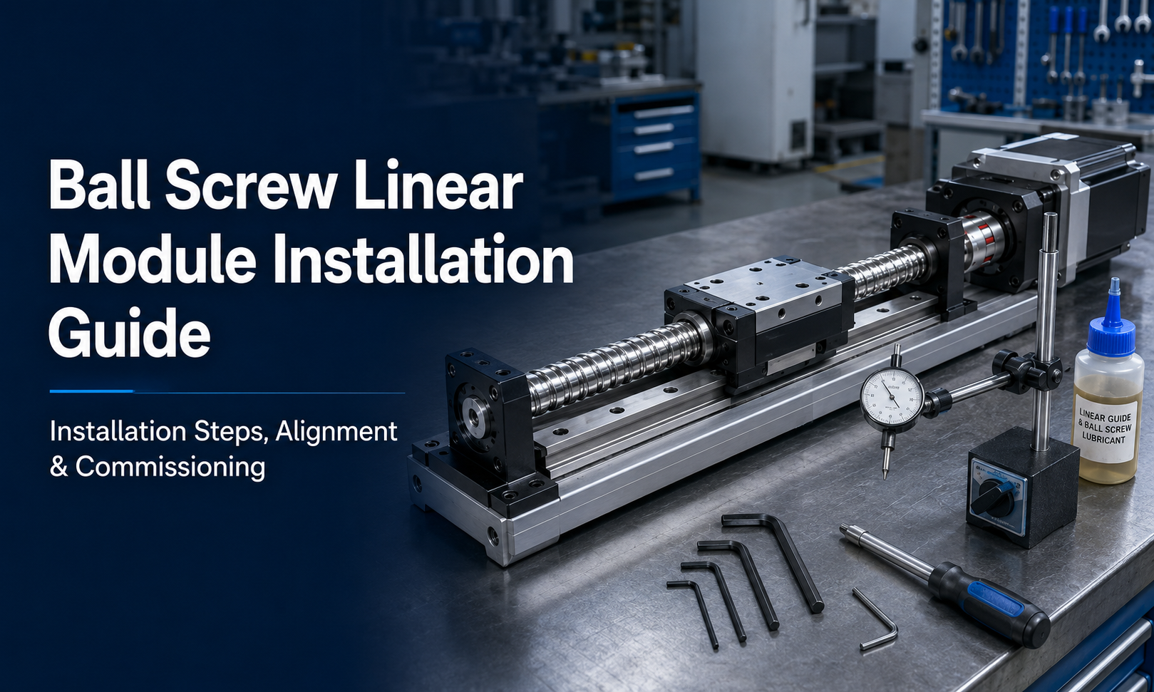
Why Correct Installation Matters
A ball screw linear module combines a ball screw, linear guide, carriage, bearings, coupling and motor into one motion system. These components must remain accurately aligned during operation.
Improper installation may cause:
- Increased running resistance
- Abnormal vibration or mechanical noise
- Reduced positioning accuracy
- Uneven guide or ball screw wear
- Coupling damage
- Motor overload or alarm
- Shortened bearing and ball screw service life
The objective of installation is not simply to fasten the module to the machine. The mounting process must preserve the module’s straightness, parallelism and internal alignment.
Tools and Materials Required
Prepare the necessary tools before beginning the installation. The exact tools depend on the module size and machine structure, but a typical installation requires:
- Torque wrench
- Hex keys and suitable screwdrivers
- Dial indicator
- Magnetic indicator base
- Precision straightedge
- Feeler gauges
- Spirit level or electronic level
- Cleaning cloths
- Industrial cleaning agent
- Lubricating grease recommended for the ball screw and linear guide
- Thread-locking compound where specified
- Shims for alignment adjustment
Use clean and calibrated measuring tools. Contaminated or damaged tools can introduce measurement errors during alignment.
1. Inspect the Ball Screw Linear Module
Before installation, inspect the module for transportation damage, loose fasteners or contamination.
Check the following items:
- The aluminum base or steel structure is not bent or damaged.
- The protective cover or sealing strip is correctly positioned.
- The carriage moves smoothly through the available travel.
- The motor mounting plate and coupling are undamaged.
- The sensor brackets and cables are secure.
- No foreign material is present on the guide, screw or mounting surface.
Do not force the carriage to move when abnormal resistance is detected. Identify the cause before continuing with the installation.
2. Prepare the Mounting Surface
The mounting surface directly affects the straightness and operating accuracy of the module. It should be flat, rigid, clean and capable of supporting the module and payload without excessive deformation.
Clean the Surface
Remove oil, dust, metal chips, paint residue, burrs and other contaminants from both the machine base and the bottom of the linear module.
Pay particular attention to:
- Threaded mounting holes
- Locating shoulders
- Dowel-pin holes
- Reference edges
- Recessed mounting areas
A small metal chip trapped under the base can twist the module after the bolts are tightened.
Check Flatness and Rigidity
Use a precision straightedge, level or dial indicator to inspect the mounting surface. The permissible flatness error should be determined according to the module accuracy grade, length and manufacturer specifications.
For long-stroke modules, measure several points along the entire mounting surface rather than checking only the two ends.
Remove Burrs
Inspect all edges and holes for raised burrs. Carefully remove them without damaging the reference surface.
3. Position the Module on the Machine
Lift the module using appropriate handling equipment. Long or heavy modules should be supported at multiple points to prevent bending.
Never lift the module by:
- The motor cable
- The sensor cable
- The protective cover
- The coupling
- The carriage alone
Place the module gently on the prepared mounting surface. Align its reference side with the machine’s locating shoulder or reference edge where available.
4. Horizontal Installation
Horizontal mounting is the most common arrangement for ball screw linear modules. In this orientation, the module mainly carries the payload through the linear guide system.
Initial Fastening
Insert the mounting bolts but do not fully tighten them. Keep the bolts slightly loose so the module can move during alignment.
Align the Reference Side
Push the module gently against the locating shoulder. For modules without a locating shoulder, use a dial indicator to establish a straight reference line.
Tighten in Sequence
After alignment, tighten the mounting bolts gradually. Begin near the center and work toward both ends, alternating sides where appropriate.
This tightening sequence reduces the risk of twisting or bending the module base.
Verify Smooth Movement
Move the carriage slowly through the complete stroke after preliminary tightening. Running resistance should remain consistent from one end to the other.
If resistance increases at a specific position, loosen the nearby bolts and check the mounting surface and alignment again.
5. Vertical Installation
Vertical installation requires additional safety and load considerations because gravity continuously acts on the carriage and payload.
Support the Moving Carriage
Secure the carriage before installing the motor, brake or load. Without support, the carriage may move downward unexpectedly.
Suitable safety measures may include:
- A mechanical support block
- A temporary locking fixture
- A motor with an electromagnetic brake
- A counterbalance mechanism
- A safety brake or anti-fall device
Confirm Vertical Load Capacity
The allowable vertical payload may differ from the allowable horizontal payload. Confirm that the selected ball screw, motor torque, brake capacity and safety factor are suitable for the vertical load.
Check Back-Driving Risk
Many ball screws can be back-driven by the payload when motor power is removed. Do not rely on the ball screw alone to hold a suspended load.
Verify Lubrication Distribution
Vertical orientation can influence grease distribution. Follow the lubrication method and maintenance interval recommended for the selected module.
6. Adjust Straightness and Parallelism
Alignment is especially important when the linear module works with another axis, a fixed guide, a gantry crossbeam or external machine tooling.
Straightness Measurement
Mount a dial indicator on a stable reference structure and measure along the module’s reference edge or carriage travel.
Make small adjustments by:
- Moving the module laterally
- Using precision shims
- Adjusting the machine reference shoulder
- Loosening and retightening mounting bolts in stages
Parallelism Between Two Modules
When twoball screw modulesoperate in parallel, such as in a dual-axis gantry system, poor parallelism can create internal stress and uneven loading.
Measure:
- The distance between both module reference edges
- The height difference between the two carriages
- The parallelism of the travel directions
- The squareness between the moving axis and crossbeam
Do not use the gantry crossbeam to force two misaligned modules into position. Align the modules first, then install and adjust the crossbeam.
7. Install the Coupling
The coupling connects the motor shaft to the ball screw input shaft. Incorrect installation can create axial force, radial load, vibration and premature bearing wear.
Inspect the Shafts
Clean the motor shaft and ball screw shaft. Remove oil, burrs and contamination. Confirm that both shaft diameters match the coupling specification.
Maintain the Correct Shaft Gap
Do not insert both shafts so deeply that they contact each other inside the coupling. Maintain the required gap specified for the coupling design.
Avoid Excessive Axial Force
Do not hammer, press or force the coupling onto the shafts. Excessive force can damage the ball screw support bearings or motor bearings.
Tighten Evenly
Position the coupling correctly and tighten the clamping screws evenly using the specified torque. Where multiple clamping screws are used, tighten them gradually in sequence.
Check Concentricity
The motor shaft and ball screw shaft should be aligned as closely as possible. Flexible couplings can compensate for small installation errors, but they should not be used to correct major misalignment.
8. Mount the Motor
Install the servo motor or stepper motor on the motor mounting plate without allowing the motor weight to pull on the coupling.
The recommended sequence is:
- Support the motor in line with the ball screw shaft.
- Insert the motor shaft into the coupling.
- Lightly fasten the motor mounting bolts.
- Check that the motor flange sits flat against the mounting plate.
- Tighten the motor bolts gradually in a diagonal sequence.
- Tighten the coupling clamps to the specified torque.
- Rotate or jog the system slowly to check for binding.
Do not use the mounting bolts to pull a misaligned motor flange into position. Correct the alignment before final tightening.
9. Install and Adjust Sensors
Ball screw linear modules commonly use origin sensors, positive limit sensors and negative limit sensors.
Sensor Functions
| Sensor | Main Function | Installation Consideration |
|---|---|---|
| Origin sensor | Establishes the machine reference position | Position it where repeatable homing can be completed safely. |
| Positive limit sensor | Prevents excessive travel in the positive direction | Leave sufficient stopping distance before the mechanical end. |
| Negative limit sensor | Prevents excessive travel in the negative direction | Confirm that the sensor activates before mechanical contact. |
Adjust the sensor positions so that the control system can stop the carriage before it reaches the mechanical travel limit.
Secure all sensor cables away from the moving carriage, ball screw, coupling and sharp edges. Use a cable carrier where repeated cable movement is required.
10. Lubricate Before Startup
Confirm that the ball screw and linear guide have sufficient lubrication before initial operation.
Use only a lubricant compatible with:
- The ball screw nut
- The linear guide blocks
- The operating speed
- The ambient temperature
- The presence of dust, moisture or cleanroom requirements
Do not mix incompatible grease types. When changing lubricant, clean out the previous grease according to the maintenance procedure.
After lubrication, move the carriage slowly through the full stroke several times to distribute the lubricant evenly.
11. Electrical and Control Checks
Before applying power, inspect the motor, sensor and grounding connections.
Confirm that:
- The motor phases or servo cables are connected correctly.
- The encoder cable is securely installed.
- The sensor voltage matches the controller input.
- The positive and negative limit signals are assigned correctly.
- The motor brake is wired correctly for vertical applications.
- The emergency stop circuit is functional.
- The motor rotation direction matches the commanded travel direction.
Keep power cables separated from low-voltage sensor and encoder cables where possible to reduce electrical interference.
12. Commissioning Procedure
Commission the module gradually. Do not begin with maximum speed, acceleration or payload.
Step 1: Manual Inspection
Check all fasteners, cable routes, covers, sensors and safety devices. Make sure no tools or temporary supports remain in the travel area.
Step 2: Low-Speed Jogging
Run the carriage at low speed over a short distance. Confirm the actual movement direction and check for unusual sound or vibration.
Step 3: Full-Stroke Test
Move the carriage slowly through the complete usable stroke. Verify that both limit sensors operate before the carriage reaches the mechanical ends.
Step 4: Homing Test
Run the homing sequence several times. The origin position should be detected consistently.
Step 5: Gradual Speed Increase
Increase speed and acceleration in stages while monitoring motor current, vibration, temperature and positioning behavior.
Step 6: Load Test
Add the payload gradually. Confirm that the motor torque, braking performance and positioning accuracy remain within the required range.
Step 7: Accuracy Verification
Measure positioning accuracy, repeatability and travel straightness using suitable measuring equipment. Apply controller compensation only after mechanical installation errors have been minimized.
Common Installation Mistakes
| Installation Mistake | Possible Result | Corrective Action |
|---|---|---|
| Installing on an uneven surface | Base deformation, uneven resistance and accuracy loss | Clean, measure and correct the mounting surface before tightening. |
| Tightening one end completely first | Twisting or bending of the module base | Tighten gradually from the center toward both ends. |
| Using the coupling to compensate for major misalignment | Coupling fatigue and bearing damage | Realign the motor shaft and ball screw shaft. |
| Operating without sufficient lubrication | High friction, noise and premature wear | Lubricate the ball screw and guide before commissioning. |
| Incorrect limit sensor position | Mechanical collision or overtravel | Provide adequate stopping distance before both travel ends. |
| No brake or support in a vertical application | Unexpected downward movement | Use a motor brake, mechanical support or anti-fall device. |
| Starting immediately at full speed | Collision, vibration or control instability | Commission the system at low speed and increase parameters gradually. |
Installation Checklist
- The mounting surface is clean, flat and rigid.
- The module base is not twisted after tightening.
- The mounting bolts are tightened to the specified torque.
- The carriage moves smoothly through the full stroke.
- The motor shaft and ball screw shaft are aligned.
- The coupling is correctly positioned and tightened.
- The motor flange is mounted flat against the motor plate.
- The origin and limit sensors operate correctly.
- The ball screw and linear guide are properly lubricated.
- The cables are secured and protected from moving components.
- Vertical loads are protected by a brake or mechanical safety device.
- Low-speed, full-stroke, homing and load tests have been completed.
Maintenance After Installation
Inspect the installation again after the initial operating period. Fasteners may settle slightly during early operation, especially on long modules or machines exposed to vibration.
Periodic maintenance should include:
- Checking mounting and motor bolts
- Inspecting the coupling
- Checking sensor positions
- Monitoring noise and vibration
- Lubricating the ball screw and linear guides
- Inspecting cables and protective covers
- Verifying positioning repeatability
Any sudden increase in noise, resistance, temperature or motor current should be investigated before continued operation.
Conclusion
Successful ball screw linear module installation depends on careful surface preparation, accurate alignment, controlled bolt tightening, correct coupling and motor installation, reliable sensor adjustment and sufficient lubrication.
Horizontal installations require accurate support and straightness, while vertical installations also require protection against back-driving and falling loads. Commissioning should always begin at low speed and progress gradually toward the required operating conditions.
Following a structured installation and inspection process helps the ball screw linear module achieve stable motion, high positioning accuracy and a long operating life.
