 English

A ball screwlinear moduleis a precision linear motion system that converts rotary motor motion into controlled linear travel. Its positioning accuracy, load capacity, rigidity, service life and operating stability depend not only on the ball screw itself, but also on the mechanical relationship between the base, linear guides, carriage, support bearings, coupling, motor mount, protective cover and sensors.
Understanding the internal structure of a ball screw linear module helps engineers evaluate module quality, select the correct configuration and identify the source of positioning errors, vibration, noise or premature wear.
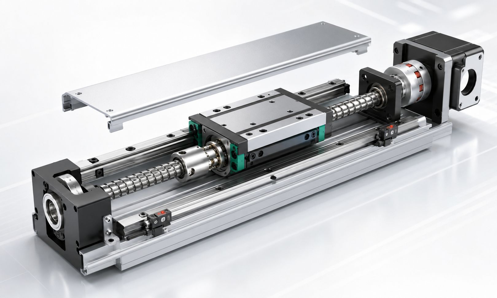
Structural Overview of a Ball Screw Linear Module
A typical ball screw linear module consists of the following main components:
- Aluminum base or structural body
- Precision ball screw shaft
- Ball nut assembly
- Linear guide rails and guide blocks
- Moving carriage or worktable
- Fixed-end bearing support
- Floating-end bearing support
- Flexible or rigid coupling
- Motor mounting bracket
- Protective cover or sealing system
- Limit, origin and position sensors
During operation, the motor rotates the ball screw through the coupling. The ball nut moves along the screw shaft and transfers the axial motion to the carriage. The linear guides support the carriage and constrain it to move in a straight line, while the bearing supports maintain screw alignment and absorb axial or radial forces.
Each component performs a different mechanical function. The ball screw generates linear movement, the guide system supports external loads, and the base maintains the alignment of the complete assembly.
1. Aluminum Base
The aluminum base is the main load-bearing body of the linear module. It provides mounting surfaces for the ball screw, linear guides, bearing supports, protective covers and motor assembly.
Main functions of the aluminum base
- Maintains the parallel relationship between the ball screw and guide rails
- Supports the moving and stationary components
- Transfers external forces to the machine frame
- Protects internal transmission parts
- Provides mounting holes and reference surfaces
- Improves the overall bending and torsional rigidity of the module
Most standard ball screw modules use extruded aluminum alloy profiles because aluminum provides a useful balance between structural rigidity, low weight, corrosion resistance and manufacturing cost.
The internal ribs and cross-sectional geometry of the profile strongly affect module stiffness. A larger profile does not automatically provide better performance unless the wall thickness, reinforcing ribs and guide mounting surfaces are properly designed.
The guide mounting surfaces and support-unit mounting surfaces normally require precision machining after extrusion. Inadequate machining accuracy can cause guide misalignment, uneven preload and increased resistance during travel.
2. Ball Screw
The ball screw is the primary transmission component of the module. It converts motor rotation into linear displacement through the rolling contact between the screw raceway, recirculating balls and ball nut.
Compared with a conventional sliding lead screw, a ball screw offers lower friction, higher transmission efficiency, better positioning accuracy and reduced wear.
Important ball screw parameters
- Screw diameter:Influences axial load capacity, rigidity and critical speed.
- Lead:Determines the linear travel produced by one screw revolution.
- Accuracy grade:Influences lead error and positioning accuracy.
- Preload:Reduces axial clearance and improves rigidity.
- Effective stroke:Defines the available carriage travel.
- Critical speed:Limits the maximum rotational speed for a given screw length.
- Buckling capacity:Determines resistance to axial compression on long strokes.
A small screw lead provides higher mechanical resolution and greater thrust for a given motor torque, but normally results in lower maximum linear speed. A larger lead increases travel speed but may reduce available thrust and positioning resolution.
For long-stroke applications, screw diameter, support configuration and rotational speed must be carefully evaluated. When the screw rotates too quickly, it may produce whipping, vibration and excessive noise.
3. Ball Nut
The ball nut surrounds the ball screw and contains the recirculating steel balls. As the screw rotates, the balls roll through the raceways and continuously return through an internal or external circulation system.
The ball nut is normally connected to a nut housing or directly attached to the moving carriage. It is responsible for transmitting axial force from the screw to the worktable.
Common ball nut configurations
- Single-nut configuration
- Preloaded single nut
- Double-nut preload configuration
- Flanged ball nut
- Cylindrical ball nut
Preloaded ball nuts are commonly used in precision automation equipment. Preload removes or reduces axial clearance between the nut and screw, improving bidirectional positioning repeatability and axial rigidity.
However, excessive preload increases friction, motor load and heat generation. The preload level should therefore match the required accuracy, duty cycle and service life rather than being selected as high as possible.
4. Linear Guide
The linear guide system supports the carriage and controls its motion direction. It typically consists of one or two guide rails and multiple recirculating-ball guide blocks.
The ball screw should primarily transmit axial driving force. External vertical loads, lateral loads and moment loads should be carried by the linear guides rather than by the screw shaft.
Functions of the linear guide
- Supports the payload and carriage weight
- Maintains straight-line movement
- Resists radial, lateral and moment loads
- Reduces sliding friction
- Improves motion smoothness
- Prevents the carriage from rotating around the screw axis
Guide-rail size, block quantity, preload level and installation spacing determine the load and moment capacity of the module. Wider spacing between guide blocks generally improves resistance to pitch, yaw and roll moments.
The parallelism between the guide rail and ball screw is especially important. Misalignment can create uneven guide loading, screw bending and abnormal wear.
5. Moving Carriage
The carriage, also called the worktable or slider, is the moving platform used to mount a workpiece, gripper, dispensing head, inspection camera or other automation equipment.
The carriage connects the ball nut to the guide blocks, allowing the screw-generated axial motion to move the complete payload along the guide rails.
Carriage design considerations
- Mounting-hole pattern
- Table length and width
- Material thickness
- Flatness of the mounting surface
- Guide-block spacing
- Ball-nut mounting rigidity
- Allowable payload and moment load
A longer carriage can provide larger mounting space and improved moment resistance, but it also increases moving mass. Higher moving mass requires more motor torque during acceleration and deceleration.
The carriage must be sufficiently rigid to prevent deformation under load. Carriage deflection can affect tool position even when the ball screw and encoder indicate that the commanded position has been reached.
6. Fixed-End and Floating-End Supports
The ball screw is normally supported by bearing units at both ends. The drive end is typically designed as the fixed end, while the opposite side acts as the floating or support end.
Fixed-end support
The fixed end usually contains a pair of angular-contact bearings installed in a back-to-back or face-to-face arrangement. This bearing set controls axial displacement and provides radial support for the screw.
The fixed support performs several important functions:
- Locates the ball screw axially
- Absorbs axial thrust in both directions
- Maintains rotational accuracy
- Improves axial rigidity
- Connects the screw shaft to the motor side
Floating-end support
The floating end usually uses a radial bearing. It supports the screw radially while allowing a small amount of axial movement caused by thermal expansion.
If both screw ends are completely constrained without considering thermal growth, temperature changes can generate unwanted axial stress and increase bearing load.
Common support configurations
- Fixed-free
- Fixed-supported
- Fixed-fixed
A fixed-supported arrangement is common in standard linear modules. A fixed-fixed configuration can provide higher rigidity and critical speed, but it requires more precise assembly and preload control.
7. Coupling
The coupling connects the motor shaft to the ball screw shaft. It transmits torque while compensating for small amounts of angular, parallel or axial misalignment.
Common coupling types
- Helical beam coupling
- Bellows coupling
- Oldham coupling
- Disc coupling
- Jaw coupling
Precision ball screw modules often use low-backlash couplings. Coupling torsional stiffness affects servo response and positioning performance, especially during rapid acceleration, deceleration and direction reversal.
A coupling that is too flexible can introduce torsional wind-up and response delay. A coupling that is too rigid may transfer assembly misalignment directly to the motor bearings and ball screw support bearings.
Correct shaft insertion depth, clamping torque and alignment are essential during assembly. Loose coupling screws can cause lost motion, abnormal noise and inconsistent positioning.
8. Motor Mount
The motor mount secures the servo motor or stepper motor to the module body and maintains alignment between the motor shaft and ball screw.
The motor mounting structure may be arranged as:
- Direct inline motor connection
- Side-mounted motor with timing belt transmission
- Folded motor configuration
- Motor with planetary gearbox
A direct inline connection offers a compact transmission path and minimizes additional backlash. A side-mounted configuration reduces the total module length and may be useful where installation space is limited.
The motor mount must have sufficient rigidity. If the mounting plate bends under motor torque, shaft alignment can change and produce coupling wear or vibration.
9. Protective Cover and Sealing System
The protective cover prevents dust, metal chips, oil droplets and foreign objects from entering the ball screw and guide system.
Common protection structures
- Stainless-steel strip cover
- Aluminum cover plate
- Bellows cover
- Telescopic cover
- Fully enclosed profile
- Dust-resistant sealing strips
The protection level should be selected according to the working environment. A standard cover may be sufficient for clean assembly or inspection equipment, while machining, welding or dusty production lines may require a more fully enclosed design.
The cover should protect internal components without generating excessive friction. Poorly adjusted sealing strips can increase running resistance and reduce usable thrust.
10. Sensors
Sensors provide position references and travel protection for the linear module. They are normally mounted along the module body or inside dedicated sensor grooves.
Common sensor functions
- Origin sensor:Establishes the machine reference position.
- Positive limit sensor:Prevents travel beyond the positive stroke boundary.
- Negative limit sensor:Prevents travel beyond the negative stroke boundary.
- Intermediate position sensor:Confirms arrival at a specified process position.
Photoelectric sensors, inductive proximity sensors and magnetic sensors are commonly used. The selected sensor must be compatible with the controller input, supply voltage, output type and required detection repeatability.
Mechanical end stops may also be installed as a secondary safety measure. However, they should not be used as the normal stopping method during production operation.
How the Components Work Together
The structural relationship of a ball screw linear module can be summarized as follows:
- The motor is installed on the motor mount.
- The motor shaft connects to the ball screw through the coupling.
- The ball screw is located by the fixed support and stabilized by the floating support.
- The ball nut is mounted inside or below the moving carriage.
- The carriage is supported by guide blocks running on the linear guide rails.
- The aluminum base maintains the relative position of the guide rails and screw supports.
- The protective cover isolates the transmission system from contaminants.
- The sensors provide homing, limit and position signals to the controller.
When the motor rotates, torque passes through the coupling to the ball screw. The rotating screw drives the nut in a linear direction. Because the nut is connected to the carriage and the carriage is constrained by the linear guides, the carriage moves along a controlled straight path.
The screw and nut generate axial motion, while the guide system carries the external payload. This separation of transmission and load-support functions is one of the most important principles inball screw moduledesign.
Important Structural Design Factors
Parallelism between the ball screw and linear guide
The screw axis and guide direction must remain parallel throughout the effective stroke. Poor parallelism increases operating resistance and may cause uneven ball-nut loading.
Guide-rail spacing
A wider guide spacing can improve moment-load capacity. However, it also increases module width and manufacturing cost.
Support-bearing preload
Correct bearing preload improves axial rigidity and rotational accuracy. Excessive preload increases heat and reduces bearing life, while insufficient preload can create axial movement.
Ball-nut preload
Nut preload improves bidirectional positioning and reduces backlash. It must be balanced against friction, temperature rise and motor torque requirements.
Structural rigidity
The rigidity of the base, carriage, support housings and motor mount affects real positioning performance. A high-accuracy screw cannot compensate for a flexible mechanical structure.
Lubrication access
The structure should allow regular lubrication of the ball nut and guide blocks. Some modules use external grease fittings or centralized lubrication ports to simplify maintenance.
Thermal expansion
Motor heat, bearing friction and repeated motion can increase the temperature of the screw and module body. Thermal expansion may produce positioning drift, especially in long-stroke or high-duty-cycle systems.
Maintenance accessibility
Sensors, grease ports, coupling clamps and mounting screws should remain accessible after the module is installed in the machine.
How Structure Affects Module Performance
| Structural Element | Main Performance Influence |
|---|---|
| Ball screw diameter and lead | Speed, thrust, resolution, rigidity and critical speed |
| Ball nut preload | Backlash, repeatability, friction and service life |
| Guide size and block spacing | Load capacity, moment resistance and motion stability |
| Base cross-section | Bending rigidity, torsional rigidity and alignment stability |
| Support-bearing arrangement | Axial rigidity, rotational stability and screw critical speed |
| Coupling stiffness | Servo response, positioning delay and vibration |
| Protective structure | Contamination resistance and maintenance interval |
| Sensor arrangement | Homing accuracy, travel safety and process control |
Common Structural Problems
Ball screw and guide misalignment
This can cause high running resistance, motor overload, vibration and uneven wear.
Loose coupling connection
A loose coupling may produce lost motion, impact noise or unstable positioning during direction changes.
Incorrect bearing preload
Excessive preload generates heat, while insufficient preload reduces axial rigidity.
Contaminated guide or screw raceways
Dust and chips can damage rolling surfaces and reduce operating life.
Insufficient carriage rigidity
A flexible carriage can deform under offset loads, producing tool-position errors even when screw travel is accurate.
Poor sensor installation
Loose brackets or inconsistent sensing gaps can cause unreliable homing or limit signals.
Ball Screw Module Structure Selection Checklist
Before selecting a ball screw linear module, evaluate the following structural requirements:
- Required effective stroke
- Horizontal, vertical and side-mounted orientation
- Payload mass and center-of-gravity position
- Axial, radial and moment loads
- Required positioning accuracy and repeatability
- Maximum speed and acceleration
- Available installation space
- Motor mounting direction
- Environmental dust, oil and moisture conditions
- Lubrication and maintenance access
- Sensor quantity and output type
- Expected duty cycle and service life
A correctly designed module combines the screw, guide, support and base as one complete mechanical system. Selecting individual components only by their nominal load ratings may not provide reliable system-level performance.
Frequently Asked Questions
What is the main structure of a ball screw linear module?
The main structure includes an aluminum base, ball screw, ball nut, linear guide rails, guide blocks, moving carriage, fixed and floating bearing supports, coupling, motor mount, protective cover and position sensors.
Does the ball screw support the payload?
The ball screw primarily transmits axial driving force. The linear guide system should support the payload, radial forces and moment loads.
Why does a ball screw module need a fixed and floating support?
The fixed support controls the axial position of the screw, while the floating support provides radial support and allows limited thermal expansion.
What connects the ball nut to the carriage?
The ball nut is normally connected through a nut housing, flange or integrated mounting structure inside the moving carriage.
Why are two guide rails used in some modules?
Two guide rails can provide higher load capacity, improved torsional rigidity and better resistance to pitch, yaw and roll moments.
How does the module structure affect accuracy?
Accuracy is affected by screw lead error, nut preload, bearing preload, guide straightness, assembly parallelism, base rigidity, carriage deformation, coupling stiffness and thermal expansion.
Can the motor be installed on the side of the module?
Yes. A folded or side-mounted motor can drive the screw through a timing belt and pulleys. This arrangement reduces overall module length but introduces additional transmission components.
What protection structure is suitable for dusty environments?
A fully enclosed body, stainless-steel strip cover, bellows or additional sealing system is generally more suitable than an open module. The exact configuration should match the type and quantity of contaminants.
Conclusion
A ball screw linear module is an integrated mechanical system rather than a ball screw installed inside an aluminum profile. The aluminum base maintains structural alignment, the ball screw and nut generate linear motion, the guides support the payload, the bearings locate the screw, and the coupling and motor mount transmit drive torque.
Protective covers and sensors further improve reliability, travel safety and environmental resistance. For accurate module selection, engineers should evaluate the complete assembly, including rigidity, preload, support configuration, lubrication, thermal behavior and mounting orientation.
A well-designed ball screw linear module structure provides accurate positioning, stable load support, smooth operation and long service life in automated assembly, inspection, dispensing, machine loading, semiconductor equipment and other precision motion applications.
