 English

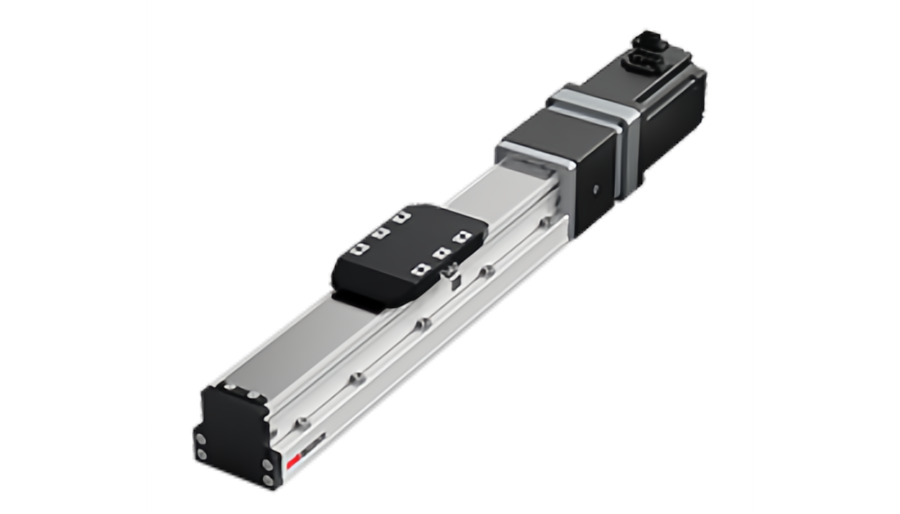
A ball screwlinear moduleconverts motor torque into linear thrust through the helical motion of the screw and nut. Compared with a timing belt drive, the relationship between torque, screw lead and thrust is much more direct, which makesball screw modulesespecially useful for precision positioning, vertical lifting and higher-thrust linear motion.
However, the theoretical torque-to-thrust conversion is only the starting point. A completeball screw linear module thrust calculationmust also account for moving mass, acceleration, gravity, guide resistance, screw efficiency, preload, motor torque at operating speed and the mechanical limits of the screw, bearings and guide system.
This guide explains how to calculate required thrust, convert motor torque into ball screw thrust, and verify whether the selected screw and drive can support the real motion cycle.
What Is Thrust in a Ball Screw Linear Module?
Thrust is the axial linear force generated along the screw direction and delivered to the moving carriage.
It should not be confused with payload capacity.
| Parameter | What It Describes |
|---|---|
| Thrust | Linear force available to accelerate the carriage or resist an external axial load |
| Payload | Mass supported by the guide system |
| Moment load | Pitch, yaw or roll load caused by an offset center of gravity |
| Ball screw axial load | Load carried through the screw/nut system |
Key distinction:a module may support a large payload through its linear guides while the ball screw is limited by motor torque, axial load, speed or life.
Step 1: Calculate the Required Linear Force
For a simplified horizontal axis:
Freq= m × a + Fresistance+ Fprocess
where:
- m= total moving mass in kg
- a= required linear acceleration in m/s2
- Fresistance= guide, seal and cable resistance in N
- Fprocess= external process force in N
What should be included in moving mass?
- Workpiece
- Fixture
- Tooling
- Upper axes in a multi-axis system
- Moving cables and cable carrier where relevant
- Any auxiliary moving hardware
Using only the product weight can underestimate the actual acceleration force significantly.
Acceleration Force: F = m × a
The dynamic force required to accelerate the moving mass is:
Facc= m × a
For example, if a 25 kg moving assembly must accelerate at 2 m/s2:
Facc= 25 × 2 = 50 N
This is only the acceleration component. Mechanical resistance and process force still need to be added.
Step 2: Include Gravity for Vertical Axes
For vertical upward acceleration:
Fup= m(g + a) + Fresistance+ Fprocess
wheregis approximately 9.81 m/s2.
For downward acceleration, gravity assists the motion and the drive may enter a braking or regenerative condition depending on the commanded acceleration.
Vertical-axis warning:thrust calculation does not replace holding and anti-fall safety design. Power-loss behavior must be evaluated separately.
Step 3: Convert Ball Screw Torque Into Linear Thrust
The ideal torque-to-thrust relationship for a ball screw is:
T = F × p ÷ (2π × η)
Rearranging for thrust:
F = 2π × η × T ÷ p
where:
- F= linear thrust in N
- T= torque applied to the screw in N·m
- p= screw lead in m/rev
- or= screw transmission efficiency
This equation is the core ofball screw torque to thrustconversion.
Why Screw Lead Has Such a Strong Effect on Thrust
Screw lead is the linear distance traveled by the nut per one screw revolution.
For the same screw torque:
- A smaller lead produces more theoretical thrust.
- A larger lead produces less theoretical thrust.
But lead also changes the required screw speed for a given linear velocity.
Therefore, lead creates a direct trade-off between:
- Thrust
- Linear speed
- Motor rpm
- Positioning resolution from motor rotation
Lead and Speed Must Be Checked Together
Screw rotational speed is:
n = 60 × v ÷ p
where:
- n= screw speed in rpm
- v= linear speed in m/s
- p= screw lead in m/rev
A smaller lead increases thrust but also requires more rpm to reach the same linear speed.
A larger lead reduces rpm requirement but also reduces thrust per unit motor torque.
A Simple Torque-to-Thrust Example
Assume:
- Motor torque at the screw: 1.5 N·m
- Ball screw lead: 10 mm/rev = 0.010 m/rev
- Transmission efficiency: 0.90
The theoretical useful thrust is:
F = 2π × 0.90 × 1.5 ÷ 0.010
F ≈ 848 N
This value is much higher than many belt-driven systems can generate from the same motor torque, which illustrates why ball screws are attractive for thrust-intensive applications.
But 848 N is not automatically the allowable module thrust.The screw dynamic load rating, support bearings, nut preload, motor speed and guide structure still need to be checked.
Step 4: Calculate the Torque Required for a Known Thrust
If the application force is known, use:
Tload= Freq× p ÷ (2π × h)
This gives the torque required to generate the linear load force through the screw.
However, this is not yet the total motor torque because rotating inertia and other losses also need to be included.
Step 5: Include Screw and Motor Rotational Inertia
During acceleration, the motor must accelerate both the moving mass and the rotating components.
Rotational acceleration torque is:
Tacc,rot= J × a
where:
- J= total rotating inertia reflected to the motor
- a= angular acceleration
For a directly driven ball screw:
α = 2π × a ÷ p
So higher linear acceleration and smaller screw lead can create a substantial rotational acceleration requirement.
The Screw Itself Can Have Significant Rotational Inertia
Long or large-diameter ball screws can have meaningful rotational inertia.
At high acceleration, the motor must accelerate:
- Motor rotor
- Coupling
- Ball screw
- Gearbox if used
This is one reason motor sizing based only on linear thrust can underestimate peak torque.
Equivalent Inertia of the Moving Mass
The translating mass can be reflected into an equivalent rotational inertia at the screw:
Jtrans= m × (p ÷ 2π)2
This is useful when sizing the motor and evaluating inertia matching.
The complete inertia model may include:
- Motor rotor inertia
- Screw inertia
- Coupling inertia
- Reflected translating mass
- Gearbox inertia
Step 6: Add Friction and Preload Torque
Ball screws are efficient, but they are not frictionless.
Additional torque may come from:
- Nut preload
- Support-bearing preload
- Guide resistance
- Seals and wipers
- Misalignment
- Lubrication condition
Preloaded precision screws can have higher no-load torque than non-preloaded screws.
This should be included in motor sizing, especially for small motors or low-speed precision axes.
Efficiency Should Match the Actual Screw and Operating Condition
Ball screws generally have high mechanical efficiency, but the exact value depends on:
- Ball screw design
- Lead angle
- Preload
- Lubrication
- Speed
- Manufacturing quality
Use manufacturer data whenever possible instead of assuming one fixed efficiency for every screw.
A Complete Horizontal-Axis Example
Consider a horizontal ball screw module with:
- Moving mass: 18 kg
- Acceleration: 2.5 m/s2
- Guide and cable resistance: 12 N
- External process force: 40 N
- Ball screw lead: 10 mm/rev = 0.010 m/rev
- Screw efficiency: 0.90
1. Acceleration force
Facc= 18 × 2.5 = 45 N
2. Total required thrust
Freq= 45 + 12 + 40 = 97 N
3. Load torque required at the screw
Tload= 97 × 0.010 ÷ (2π × 0.90)
Tload≈ 0.172 N·m
This torque is only the linear-load component.
Motor selection still needs:
- Screw rotational inertia
- Motor rotor inertia
- Acceleration torque
- Preload torque
- Peak and RMS torque checks
A Vertical-Axis Example
Assume:
- Moving mass: 8 kg
- Upward acceleration: 1.5 m/s2
- Resistance: 8 N
- No external process force
- Lead: 5 mm/rev = 0.005 m/rev
- Efficiency: 0.90
1. Upward thrust requirement
Fup = 8 × (9.81 + 1.5) + 8
Fup≈ 98.5 N
2. Required load torque
Tload= 98.5 × 0.005 ÷ (2π × 0.90)
Tload≈ 0.087 N·m
Again, this is only the torque required to support the linear load through the screw. Rotational acceleration and brake requirements still need to be considered.
Vertical Axes Also Need Brake and Regeneration Analysis
When a vertical axis moves downward, gravity may drive the screw rather than resist it.
The system may need to handle:
- Regenerative energy
- Motor braking
- Holding brake
- Power-loss behavior
- Mechanical anti-fall protection
A ball screw can be backdrivable depending on lead, efficiency and load. Do not assume the screw will self-lock.
How Screw Lead Changes Torque and Speed
| Smaller Lead | Larger Lead |
|---|---|
| More thrust per unit torque | Less thrust per unit torque |
| Higher rpm for the same linear speed | Lower rpm for the same linear speed |
| Finer mechanical travel per revolution | Greater travel per revolution |
| Often better for force-oriented axes | Often better for higher-speed motion |
The correct lead is therefore a system choice, not simply a “precision” choice.
Ball Screw Thrust Is Limited by More Than Motor Torque
Even if the motor can generate enough torque, the usable module thrust may be limited by:
- Ball screw dynamic load rating
- Ball screw static load rating
- Nut preload
- Support-bearing capacity
- Screw buckling in compression
- Screw critical speed
- Coupling capacity
- Motor shaft capacity
- Guide load and moment capacity
System rule:the allowable module thrust is the lowest safe limit in the entire force path, not the largest number obtained from the torque equation.
Check Dynamic Load Rating for Service Life
A ball screw may survive a high peak force but have unacceptable life if it experiences that force too often.
Service-life calculations typically depend on:
- Equivalent axial load
- Dynamic load rating
- Duty cycle
- Travel distance
- Lubrication
- Contamination
The exact life formula and correction factors should follow the selected ball screw manufacturer's method.
Static Load Rating Also Matters
Static overload can permanently damage the ball grooves or balls even if the axis moves only rarely.
Static checks are especially important for:
- Pressing loads
- Shock loads
- Emergency stops
- Vertical axes
- Transport or handling shocks
Compression Can Create Screw Buckling
When the screw is subjected to large compressive axial force, long slender screws can buckle.
Buckling risk increases with:
- Long unsupported screw length
- Small screw diameter
- Higher compression force
- Less rigid end support
For long-stroke high-thrust axes, screw buckling can become more important than motor torque.
High Speed Can Create Critical-Speed Limits
A long rotating screw has a critical-speed limit where shaft vibration can rise sharply.
This is why a ball screw axis cannot be scaled to unlimited stroke and speed simply by increasing motor rpm.
Critical speed depends on:
- Screw diameter
- Unsupported length
- End-support condition
- Screw straightness
Long-stroke high-speed axes should always be checked against manufacturer critical-speed data.
Support Bearing Arrangement Affects Thrust Capacity
Ball screw modules can use different support configurations, such as fixed-supported or fixed-fixed arrangements.
Support design influences:
- Axial stiffness
- Critical speed
- Thermal behavior
- Axial load capacity
A high-capacity screw paired with undersized support bearings can still produce a weak drive system.
Preload Improves Rigidity but Adds Torque
Ball screw preload reduces axial play and can increase stiffness, which is valuable for precision positioning.
However, higher preload can also increase:
- No-load torque
- Heat generation
- Lubrication demand
- Motor RMS torque
Preload should match the precision and stiffness requirement rather than simply using the highest available preload.
How to Estimate Maximum Thrust From Available Torque
If the torque available at the screw is known:
Favailable= 2π × η × Tavailable÷ p
But this value must then be reduced to the allowable system value after checking:
- Screw load rating
- Bearing capacity
- Buckling
- Critical speed
- Coupling
- Guide structure
How to Estimate Maximum Acceleration From Available Thrust
For a horizontal axis:
amax= (Favailable- Fresistance- Fprocess) ÷ m
This result should still be limited by motor peak torque, screw rotational inertia and machine stiffness.
How to Estimate Maximum Moving Mass
At a specified horizontal acceleration:
mmax= (Favailable- Fresistance- Fprocess) ÷ a
This is a drive-force estimate only.
The guide system may impose a lower mass limit because of moment load or life requirements.
Motor Torque Must Be Checked at the Required Screw Speed
Do not use motor rated torque without checking the operating rpm.
The required motor evaluation should include:
- Torque-speed curve
- Peak torque
- Continuous or RMS torque
- Maximum motor speed
- Drive current and voltage
- Thermal limits
A motor may have enough torque at low speed but insufficient torque at the rpm required by a small-lead screw.
Gear Reduction Can Increase Screw Torque
If a gearbox is used:
Tscrew= Tmotor× i × ngear
whereiis reduction ratio.
This can increase available screw torque but also:
- Raises required motor speed
- Adds gearbox inertia
- Adds efficiency loss
- May add backlash depending on gearbox type
Thrust and Payload Capacity Are Different Checks
The ball screw creates axial force, while the guide system supports the carriage and external loads.
Payload capacity is influenced by:
- Guide size
- Guide spacing
- Carriage length
- Center-of-gravity offset
- Mounting orientation
Thrust capacity is influenced more strongly by:
- Screw lead
- Motor torque
- Screw efficiency
- Screw axial rating
- Support bearings
Both must be satisfied for a complete module selection.
Common Ball Screw Thrust Calculation Mistakes
Using payload weight directly as horizontal thrust
On a horizontal axis, gravity is carried mainly by the guide and does not become full axial drive force.
Ignoring acceleration
High acceleration can create more force than guide friction.
Forgetting vertical gravity
Vertical upward motion must includemg.
Using theoretical screw efficiency for every application
Preload, lubrication and screw design can change actual efficiency.
Ignoring screw rotational inertia
Long and large-diameter screws can require significant acceleration torque.
Ignoring screw critical speed
A motor capable of high rpm does not mean the screw can safely run at that rpm.
Ignoring buckling
High compressive thrust on a long slender screw can become a structural limit.
Confusing thrust with guide payload
Axial force and guide load/moment limits are different calculations.
A Practical Ball Screw Thrust Calculation Workflow
- Define moving mass.
- Define stroke, speed and acceleration.
- Calculate horizontal or vertical required force.
- Add process force and measured resistance.
- Select preliminary screw lead.
- Convert required thrust into screw torque.
- Add rotational acceleration torque.
- Add preload and friction torque.
- Check motor peak and RMS torque at operating speed.
- Check screw dynamic and static load ratings.
- Check critical speed and buckling.
- Check support bearings and coupling.
- Check guide payload and moment capacity.
- Add an appropriate engineering margin.
What QRXQ Needs for a Ball Screw Thrust Calculation
- Moving mass
- Stroke
- Maximum speed
- Acceleration
- Horizontal or vertical installation
- External process force
- Ball screw diameter and lead
- Motor model
- Gearbox ratio if used
- Required positioning accuracy
- Daily cycle count
- Expected service life
The correct thrust value is a system result.Screw lead converts torque into force, but the final allowable thrust is controlled by the motor, screw, bearings, supports, guide system and real motion cycle together.
QRXQ evaluates ball screw linear module thrust by combining required process force, acceleration, lead, efficiency, motor torque and screw mechanical limits instead of relying only on a theoretical torque-to-thrust conversion.
