 English

Ball screw linear modulesprovide accurate, rigid and repeatable linear motion, but positioning errors, abnormal noise, vibration, overheating or screw jamming may occur when components are worn, contaminated, incorrectly adjusted or improperly installed. This guide explains how to diagnose common ball screw module problems, identify their root causes and restore stable operation.
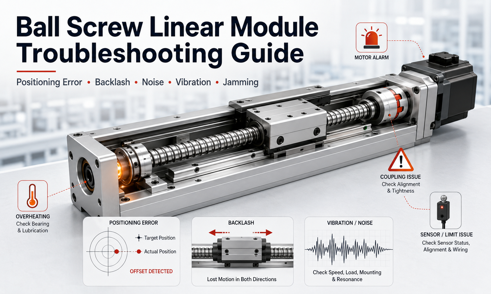
Key Troubleshooting Principles
- Stop the machine immediately when severe noise, jamming, overheating or uncontrolled motion occurs.
- Disconnect and secure the power supply before inspecting mechanical components.
- Record alarm codes, operating conditions and recent maintenance activities.
- Check external installation conditions before disassembling the module.
- Inspect mechanical, electrical and control-system factors separately.
- Change only one parameter or component at a time so that the actual cause can be confirmed.
1. Preparation Before Troubleshooting
Effective ball screw linear module troubleshooting begins with accurate information. Avoid immediately replacing the motor, ball screw or controller before confirming whether the problem originates from the module itself.
Record the Failure Conditions
Document when and how the failure occurs. Important information includes:
- Whether the fault occurs during startup, acceleration, constant-speed travel or deceleration.
- Whether it appears at one position or throughout the complete stroke.
- Whether the problem occurs only under load.
- Whether the failure is intermittent or continuous.
- Whether maintenance, lubrication or parameter changes were recently performed.
- Whether the motor driver displays an alarm code.
Perform an Initial Visual Inspection
Before dismantling the module, inspect the mounting bolts, motor connection, coupling, cable routing, sensors, protective cover and lubrication condition. Loose fasteners, damaged cables and foreign material are common causes that can often be identified without disassembly.
2. Positioning Error
Positioning error means that the carriage does not reach the commanded position or that the measured position differs from the required position. The error may be constant, cumulative or inconsistent.
Common Causes
- Loose coupling or slipping connection between the motor and ball screw.
- Incorrect pulse equivalent, electronic gear ratio or screw lead setting.
- Ball screw lead error or mechanical wear.
- Insufficient preload in the ball nut or support bearings.
- Loose carriage, guide block, motor mount or bearing housing.
- Servo tuning problems, following error or encoder feedback instability.
- Excessive payload, acceleration or external resistance.
- Thermal expansion after extended operation.
- Inaccurate home sensor position.
Diagnostic Method
- Run the module without a payload and compare the actual position with the commanded position.
- Measure positioning accuracy at several points along the stroke.
- Repeat the same movement multiple times to distinguish positioning accuracy from repeatability.
- Mark the motor shaft and coupling to check for relative slipping.
- Verify the controller settings against the actual screw lead and transmission ratio.
- Check the mounting bolts, bearing seats and carriage connections.
- Monitor servo following error and motor current during movement.
Corrective Actions
Tighten loose connections to the specified torque, correct motion-control parameters and readjust the servo system. Replace a slipping or damaged coupling. When the error changes with travel position, inspect screw alignment, lead accuracy and guide parallelism. If repeatability remains poor after external causes are eliminated, the ball nut, support bearings or screw shaft may require professional inspection or replacement.
3. Excessive Backlash
Backlash is usually most visible when the module reverses direction. The motor rotates, but the carriage does not immediately respond, producing lost motion and reduced bidirectional positioning accuracy.
Common Causes
- Wear between the ball screw and ball nut.
- Loss of ball nut preload.
- Loose fixed-side support bearing or bearing locknut.
- Loose coupling, motor shaft or screw connection.
- Loose carriage mounting plate or guide block bolts.
- Elastic deformation caused by excessive load.
- Control compensation settings that no longer match the mechanical condition.
Inspection Procedure
Secure a dial indicator against the carriage and command small forward and reverse movements. Compare the motor rotation with the actual carriage displacement. Then inspect the coupling, support bearings and mounting joints individually. This helps determine whether the lost motion comes from the drive connection, bearing support or ball nut.
Corrective Actions
Retighten loose components, restore bearing preload where permitted and replace worn couplings. A worn or damaged ball nut should not be corrected only through software compensation. When mechanical backlash exceeds the application requirement, the ball screw assembly should be repaired or replaced.
4. Abnormal Noise
A healthy ball screw module normally produces a consistent rolling and motor sound. Grinding, clicking, knocking, squealing or periodic impact noise indicates that the drive system requires inspection.
| Noise Characteristic | Possible Cause | Recommended Check |
|---|---|---|
| Continuous grinding | Contamination, insufficient lubrication or damaged rolling surfaces | Inspect the screw raceway, ball nut, guide rail and lubricant condition |
| Periodic clicking | Local screw damage, coupling defect or bearing damage | Rotate the screw slowly and identify whether the noise repeats at the same position |
| Knocking during reversal | Backlash, loose coupling or loose bearing support | Check all drive connections and measure reversal clearance |
| High-pitched squeal | Insufficient lubrication, excessive preload or misalignment | Check lubricant quantity, screw alignment and bearing condition |
| Noise only at high speed | Critical-speed effects, resonance, poor alignment or incorrect servo tuning | Reduce speed temporarily and inspect installation rigidity and motion parameters |
Corrective Actions
Remove accessible contamination using a lint-free cleaning material and apply the correct lubricant in the recommended quantity. Check screw alignment, guide parallelism, coupling concentricity and support-bearing condition. Do not continue operating a module that produces metallic grinding or severe impact sounds, because damaged raceways can rapidly contaminate the complete ball circulation system.
5. Vibration During Operation
Vibration may reduce surface quality, positioning stability and component life. It can originate from the module, machine frame, payload or servo-control system.
Possible Causes
- Insufficient mounting-surface flatness or structural rigidity.
- Loose module, motor, support bearing or workpiece mounting bolts.
- Misalignment between the motor shaft, coupling and ball screw.
- Bent screw shaft or damaged support bearing.
- Excessive acceleration or abrupt motion profiles.
- Unstable servo gain or resonance in the machine structure.
- Payload center of gravity positioned too far from the carriage.
- Damaged guide blocks or uneven guide preload.
Diagnostic Method
Operate the module at several speeds and accelerations. If vibration occurs only within a narrow speed range, structural resonance or servo tuning is likely. If vibration repeats at the same screw position, inspect the screw shaft, raceway and guide system. If it increases with payload, check moment loading, mounting rigidity and acceleration settings.
Corrective Actions
Tighten the mounting structure, improve base rigidity and correct shaft alignment. Reduce acceleration and jerk temporarily to confirm whether the motion profile is contributing to the problem. Servo parameters should be adjusted by qualified personnel after mechanical looseness and installation defects have been eliminated.
6. Ball Screw Jamming
Screw jamming is a serious fault in which the carriage cannot move smoothly or the motor cannot rotate the screw. Continuing to force the module may damage the ball nut, coupling, motor or support bearings.
Common Causes
- Foreign particles entering the screw raceway or guide system.
- Dried, contaminated or unsuitable lubricant.
- Ball circulation failure inside the ball nut.
- Screw shaft bending or installation misalignment.
- Guide rail and ball screw installed with excessive parallelism error.
- Support bearing seizure.
- Mechanical interference from a cover, cable or external component.
- Carriage movement beyond the permitted stroke.
Immediate Response
- Stop the motor and disconnect the power supply.
- Do not increase motor torque to overcome the jam.
- Check for visible interference, damaged covers or trapped cables.
- Disconnect the motor or coupling only when permitted by the equipment procedure.
- Rotate the screw slowly by hand using the approved method.
- Identify whether resistance is local or present throughout the stroke.
Corrective Actions
Clean accessible contaminants and renew the lubricant when contamination is minor and no damage is visible. If the screw remains tight after the external load and motor are disconnected, inspect the ball nut, guide blocks and support bearings. A damaged ball circulation system generally requires replacement or specialist repair rather than forced operation.
7. Excessive Temperature Rise
Some temperature increase is normal during high-speed or high-duty operation. Excessive or rapidly rising temperature indicates abnormal friction, overload or incorrect adjustment.
Possible Causes
- Excessive ball nut or support-bearing preload.
- Too much grease creating additional resistance.
- Insufficient, aged or incompatible lubricant.
- Ball screw and guide rail misalignment.
- Motor overload or incorrect servo tuning.
- Continuous operation beyond the intended duty cycle.
- Excessive payload, speed or acceleration.
- Damaged bearings, ball nut or guide blocks.
Diagnostic Method
Compare temperatures at the motor, coupling, fixed bearing, ball nut and guide blocks. The location with the highest temperature often helps identify the source. Check whether motor current increases at the same time and whether the temperature rises under no-load operation.
Corrective Actions
Correct the lubricant quantity, reduce excessive load or motion intensity and check alignment. Inspect bearing preload and ball nut resistance according to the module design. Do not mix different grease types unless compatibility has been confirmed. Replace damaged rotating or rolling components when friction remains abnormal.
8. Coupling Failure
The coupling transfers motor torque to the ball screw while accommodating limited installation deviation. Cracks, looseness or excessive deformation can cause positioning errors, noise and complete loss of motion.
Typical Symptoms
- The motor rotates but the carriage does not move.
- Positioning error appears mainly during acceleration or reversal.
- Metallic knocking occurs near the motor end.
- Coupling fasteners repeatedly become loose.
- Visible cracks, deformation or wear are present.
Corrective Actions
Check the motor-shaft and screw-shaft engagement depth, clamp position and tightening torque. Verify shaft concentricity before installing a replacement. A coupling should not be used to compensate for severe shaft misalignment. Select a coupling with suitable torque capacity, speed rating and torsional stiffness for the application.
9. Engine Alarm
A motor or servo-driver alarm does not always mean that the motor is defective. Mechanical resistance, overload, wiring problems and incorrect parameters can all trigger alarms.
| Alarm Type | Possible Module-Related Cause | Inspection Focus |
|---|---|---|
| Overload alarm | Jamming, excessive load, high friction or aggressive acceleration | Check manual movement resistance, payload and motion profile |
| Overcurrent alarm | Sudden mechanical impact, seized component or motor wiring fault | Inspect the stroke for interference and check power connections |
| Following-error alarm | Loose coupling, insufficient torque, excessive resistance or unstable tuning | Compare command position, encoder feedback and motor current |
| Encoder alarm | Encoder cable damage, connector looseness or electrical interference | Inspect feedback cables, shielding and connectors |
| Overtravel alarm | Incorrect limit-sensor position, failed sensor or parameter error | Check sensor signals, installation position and travel settings |
Troubleshooting Steps
- Record the complete alarm code before resetting the driver.
- Consult the motor and driver documentation for the alarm definition.
- Check whether the carriage can move smoothly with the power isolated.
- Inspect power, encoder, brake and grounding connections.
- Verify payload, acceleration, speed and torque limits.
- Reset the alarm only after the cause has been identified or safely eliminated.
10. Sensor Failure
Home, limit and position sensors protect the module and provide reference signals. A failed or incorrectly adjusted sensor may prevent startup, cause inaccurate homing or allow overtravel.
Common Causes
- Sensor position shifted after vibration or maintenance.
- Loose connector or broken cable.
- Incorrect sensing distance.
- Contamination on the sensor or target plate.
- Incorrect input voltage or wiring polarity.
- Damaged sensor caused by impact or overtravel.
- Control-input configuration error.
Diagnostic Method
Observe the sensor indicator while moving the carriage slowly through the detection position. Confirm the input status in the controller and measure the supply voltage when necessary. Check the cable for intermittent signals by gently moving it while monitoring the input.
Corrective Actions
Clean and reposition the sensor, restore the correct sensing distance and tighten the mounting bracket. Repair damaged wiring or replace the sensor with a compatible type. After adjustment, perform low-speed homing and limit tests before returning the machine to automatic operation.
11. Ball Screw Linear Module Troubleshooting Workflow
A structured workflow prevents unnecessary disassembly and reduces the risk of replacing serviceable components.
- Confirm the symptom:Identify the exact motion, position, load and operating stage at which the problem occurs.
- Record alarms and data:Save alarm codes, position errors, motor current, speed and temperature information.
- Secure the equipment:Stop operation, isolate energy and remove the workpiece when necessary.
- Perform a visual inspection:Check fasteners, cables, sensors, covers, contamination and lubrication.
- Run a no-load test:Determine whether the fault is related to payload or external tooling.
- Separate mechanical and electrical causes:Check manual resistance and mechanical connections before changing control parameters.
- Inspect the drive train:Examine the motor mount, coupling, support bearings, ball screw and ball nut.
- Inspect the guide system:Check guide blocks, rail condition, parallelism and carriage mounting.
- Verify control settings:Confirm screw lead, pulse equivalent, travel limits, homing logic and servo parameters.
- Apply one corrective action at a time:Test after each adjustment to confirm the root cause.
- Validate the repair:Test at low speed first, then gradually restore the normal load, speed and acceleration.
- Document the result:Record the cause, repair method, replaced components and future preventive action.
12. Troubleshooting Reference Table
| Symptom | Likely Causes | Recommended Action |
|---|---|---|
| Inaccurate positioning | Loose coupling, incorrect parameters, wear or thermal expansion | Check connections, settings, repeatability and screw condition |
| Large reversal error | Backlash in the nut, bearings, coupling or mounting joints | Measure lost motion and inspect each drive connection |
| Grinding noise | Contamination, poor lubrication or damaged raceways | Stop operation, clean, lubricate and inspect rolling components |
| Vibration | Loose mounting, resonance, misalignment or excessive acceleration | Improve rigidity, correct alignment and adjust the motion profile |
| Carriage cannot move | Jamming, interference, seized bearing or ball nut damage | Remove power, check interference and inspect manual resistance |
| High temperature | Overload, excessive preload, poor alignment or incorrect lubrication | Locate the heat source and correct friction or operating conditions |
| Motor rotates without movement | Loose or broken coupling | Inspect and replace the coupling, then realign the shafts |
| Repeated servo alarm | Mechanical resistance, wiring fault or incorrect parameters | Record the code and check both mechanical and electrical systems |
| Homing failure | Sensor position, wiring or control-input problem | Test the sensor signal and readjust the detection position |
13. Preventive Measures
Many ball screw module failures can be avoided through regular inspection and controlled operating conditions.
- Keep the screw, guide rail and protective cover clean.
- Use the specified lubricant and avoid excessive grease application.
- Inspect lubrication condition according to operating time and environment.
- Check coupling, motor, bearing housing and carriage fasteners regularly.
- Prevent cutting fluid, dust, metal particles and abrasive contaminants from entering the module.
- Do not exceed the rated payload, speed, acceleration or allowable moment.
- Use smooth acceleration and deceleration profiles to reduce impact loading.
- Inspect cables and sensors before they are damaged by repeated bending.
- Record positioning accuracy, noise, temperature and motor-current trends.
- Investigate small changes before they develop into complete failure.
14. Frequently Asked Questions
Why does a ball screw linear module lose positioning accuracy?
Common causes include a loose coupling, incorrect control parameters, worn ball nut, loose support bearings, excessive load, servo following error and thermal expansion. Measure both positioning accuracy and repeatability to narrow down the cause.
What causes abnormal noise from a ball screw module?
Abnormal noise may result from insufficient lubrication, contamination, screw misalignment, damaged support bearings, worn guide blocks or damaged screw raceways. The noise location and whether it repeats at the same position are important diagnostic clues.
What should I do when the ball screw is jammed?
Stop the equipment immediately, disconnect the power and do not increase motor torque. Check for external interference, trapped cables and contamination. If the screw cannot rotate smoothly after the load and motor are isolated, inspect the ball nut, guide blocks and support bearings.
Can backlash be corrected through software compensation?
Software compensation may reduce predictable positioning error, but it does not repair mechanical wear or looseness. Excessive mechanical backlash should be corrected at the coupling, support bearings, ball nut or mounting joints.
Why does the module become hot after lubrication?
Excessive grease can increase rolling resistance and produce additional heat. An incompatible lubricant, incorrect preload or poor alignment can cause similar symptoms. Confirm the lubrication quantity and locate the main heat source before continuing operation.
When should the ball screw assembly be replaced?
Replacement should be considered when there is visible raceway damage, persistent jamming, severe backlash, abnormal noise, unstable repeatability or excessive resistance that cannot be corrected through cleaning, lubrication and alignment.
Conclusion
Reliable ball screw linear module troubleshooting requires a systematic approach. Start by confirming the failure conditions, checking external installation factors and separating mechanical problems from electrical or control-system faults. Positioning errors, excessive backlash, abnormal noise, vibration, screw jamming and overheating should be addressed early to prevent secondary damage.
When damage involves the ball circulation system, precision bearings, screw shaft or guide system, the module should be inspected and repaired by qualified personnel. Accurate maintenance records and regular preventive checks help maintain positioning performance and reduce unexpected downtime.
