 English

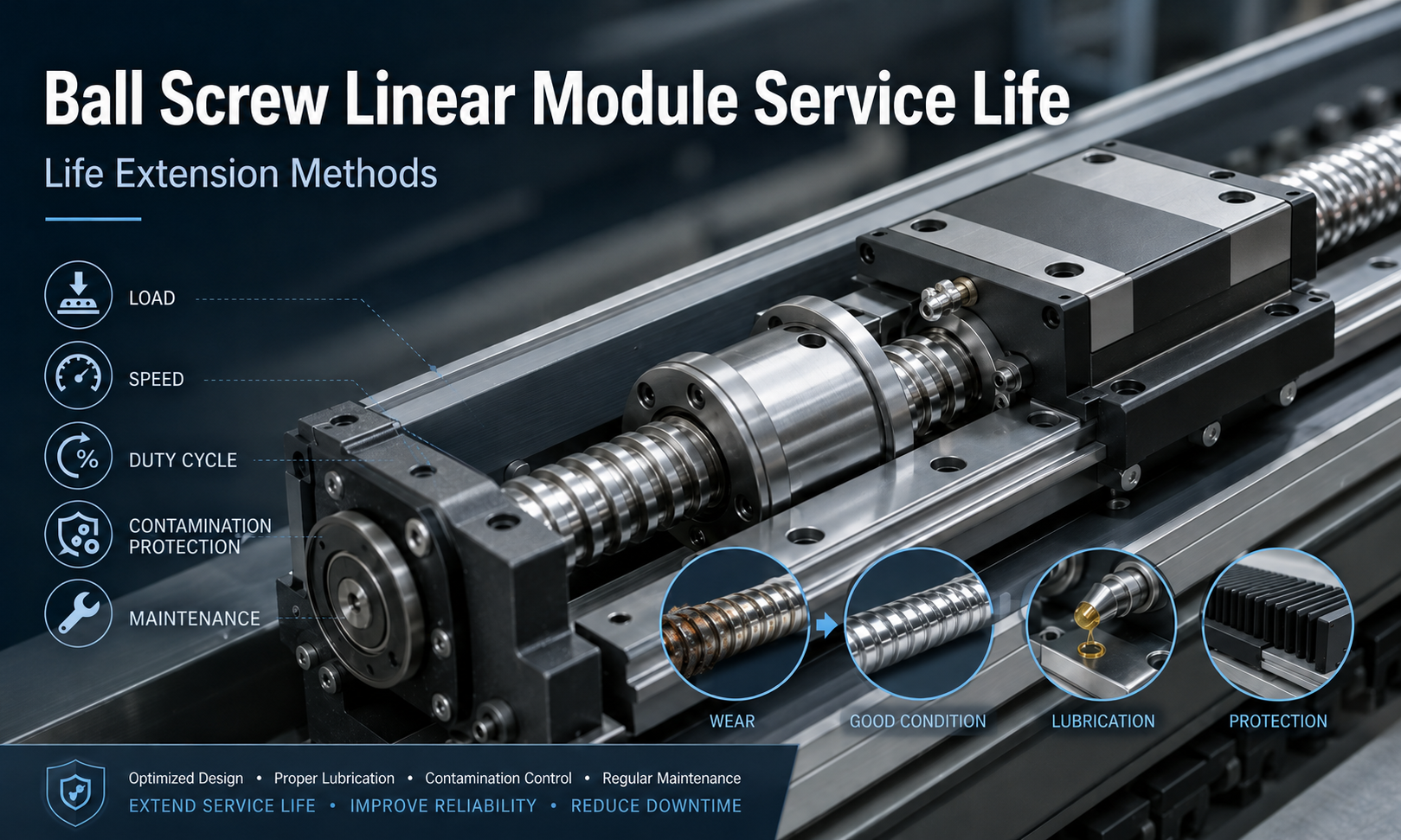
The service life of aball screw linear moduleis not determined by a single fixed number of operating hours. It depends on the fatigue life of the ball screw, linear guide, support bearings and other mechanical components, as well as the actual load, speed, acceleration, duty cycle, lubrication condition, installation accuracy and operating environment.
Under suitable operating conditions, a correctly selected and properly maintained ball screw linear module can provide reliable motion for millions of travel cycles. However, excessive load, poor lubrication, contamination, misalignment or frequent impact loads can significantly reduce its usable life.
This guide explains how ball screw linear module service life is evaluated, which factors affect durability and what measures can be taken to extend the operating life of the system.
What Does Ball Screw Linear Module Service Life Mean?
The service life of a ball screw linear module generally refers to the operating period before one or more critical components experience fatigue damage, excessive wear or performance degradation.
Alinear moduledoes not always stop working immediately when its calculated life is reached. Instead, its performance may gradually deteriorate. Common symptoms include:
- Increased positioning error
- Reduced repeatability
- Increasing backlash
- Abnormal noise or vibration
- Higher motor torque
- Increased operating temperature
- Rough or inconsistent movement
- Visible wear particles in the lubricant
For engineering calculations, service life usually refers to the rated fatigue life of the ball screw, linear guide or bearing. Actual usable life may be shorter or longer depending on operating conditions.
Main Components That Determine Module Life
The overall service life of a screw driven linear module is normally limited by the component that reaches its allowable fatigue or wear limit first.
Ball Screw Fatigue Life
The ball screw converts rotary motion from the motor into linear movement. During operation, the balls repeatedly circulate between the screw shaft and ball nut. Continuous rolling contact creates cyclic stress on the raceways.
After a large number of cycles, surface fatigue may cause flaking, pitting or spalling on the screw shaft, ball nut or circulating balls. This is one of the main factors that determines ball screw actuator lifespan.
Ball screw fatigue life is strongly influenced by:
- Equivalent axial load
- Dynamic load rating
- Rotational speed
- Acceleration and deceleration
- Preload
- Lubrication condition
- Installation alignment
- Shock and vibration
Linear Guide Life
The linear guide supports the carriage and controls its movement along the module body. Its rolling elements are subjected to repeated contact stress as the carriage moves back and forth.
Guide rail life depends on the applied vertical load, lateral load and moment load. If the payload is positioned far from the carriage center, the resulting pitch, yaw or roll moment can reduce guide life even when the total payload appears to be within the nominal load limit.
Uneven mounting surfaces, insufficient rail parallelism and poor carriage alignment may also create additional internal loads.
Support Bearing Life
The fixed-end and floating-end support bearings keep the screw shaft aligned and support axial and radial forces. Their life depends on rotational speed, preload, lubrication, installation accuracy and the axial force transmitted through the screw.
Excessive coupling misalignment or incorrect bearing installation may create additional radial force and significantly reduce bearing life.
Coupling, Seal and Auxiliary Component Life
Couplings, seals, protective covers, lubrication systems and sensors may wear before the main rolling components reach their calculated fatigue life.
For example, a damaged seal may allow dust to enter the screw and guide system. The contamination can then accelerate wear throughout the entire module.
Understanding Dynamic Load Rating
The dynamic load rating is one of the most important parameters used in ball screw life calculation.
For a ball screw, the basic dynamic load rating represents a constant axial load under which a group of identical ball screws can theoretically reach a defined rated fatigue life with a specified reliability.
The relationship between load and fatigue life is nonlinear. For ball-type rolling components, the basic life relationship is commonly expressed as:
L10= (C / P)3 × 10⁶
Where:
- L10is the basic rated life in revolutions
- Cis the basic dynamic load rating
- Pis the equivalent dynamic load
The exponent of three means that a relatively small increase in operating load can cause a large reduction in calculated life.
For example, increasing the equivalent load from 30% to 60% of the dynamic load rating does not simply reduce the life by half. Because the load is cubed in the calculation, the theoretical fatigue life may fall to approximately one eighth of the previous value.
Converting Ball Screw Life into Travel Distance
After calculating the rated life in revolutions, the result can be converted into total linear travel distance using the screw lead:
Travel distance in kilometers = L10× screw lead in millimeters ÷ 1,000,000
A larger screw lead produces more linear travel per revolution. However, lead selection also affects thrust, motor torque, speed, resolution and mechanical efficiency.
Converting Ball Screw Life into Operating Hours
The calculated number of revolutions can also be converted into operating time:
Lh= L10÷ (60 × nm)
Where:
- Lhis the calculated running life in hours
- nmis the average screw rotational speed in revolutions per minute
This value represents actual screw rotation time. When a machine operates intermittently, the estimated machine service period may be longer after the duty cycle is considered.
Example Ball Screw Life Calculation
Consider a ball screw linear module with the following simplified operating conditions:
- Basic dynamic load rating: 15 kN
- Equivalent dynamic axial load: 3 kN
- Screw lead: 5 mm
- Average screw speed while moving: 600 rpm
- Duty cycle: 50%
The theoretical rated life is:
L10 = (15 ÷ 3)3 × 106= 125,000,000 revolutions
The corresponding total travel distance is:
125,000,000 × 5 ÷ 1,000,000 = 625 km
The running life at an average speed of 600 rpm is:
125,000,000 ÷ (60 × 600) ≈ 3,472 hours
If the screw rotates during approximately 50% of the machine operating time, the estimated machine operating period would be approximately:
3,472 ÷ 0.5 ≈ 6,944 hours
This is only a simplified calculation. Actual engineering calculations should also consider acceleration forces, preload, shock factors, varying loads, speed profiles, installation orientation and environmental conditions.
How Duty Cycle Affects Service Life
Duty cycle describes the proportion of time that the module is actively moving or carrying out work during a complete operating period.
A module operating continuously has different thermal and lubrication conditions from a module that moves for ten seconds and then remains stationary for fifty seconds.
A high duty cycle can affect service life through:
- Higher average component temperature
- Faster lubricant deterioration
- More frequent circulation of the balls
- Less time for heat dissipation
- Increased motor and bearing temperature
- More accumulated travel within the same calendar period
When evaluating screw driven module durability, both total travel and actual running hours should be considered. Calendar age alone does not accurately represent mechanical fatigue.
Influence of Speed and Acceleration
High speed does not automatically mean short service life, provided that the ball screw, bearings, lubrication system and motor are correctly selected. However, increasing speed can create additional risks.
Higher Temperature
Higher rotational speed increases friction and heat generation. Excessive temperature can reduce grease viscosity, accelerate lubricant oxidation and change the thermal expansion of the screw shaft.
Critical Speed
A long screw shaft rotating at high speed may approach its critical speed. This can cause vibration, noise and screw whipping, which may damage bearings, couplings and screw raceways.
Higher Acceleration Force
Rapid acceleration and deceleration increase the dynamic force acting on the ball nut, guide blocks, bearings and coupling.
The acceleration force can be estimated using:
F = m × a
Wheremis the moving mass andais acceleration.
This force should be included when determining the equivalent operating load.
Frequent Reversal
Short-stroke, high-frequency reciprocating movement can repeatedly load the same section of the ball screw and guide rail. It may also prevent lubricant from being distributed evenly across the full travel range.
Influence of Lubrication on Ball Screw Life
Correct lubrication forms a protective film between the rolling elements and raceways. This reduces friction, limits direct metal contact, carries away heat and helps protect the components from corrosion.
Insufficient lubrication can lead to:
- Increased friction
- Higher operating temperature
- Abnormal noise
- Accelerated raceway wear
- Surface pitting
- Ball damage
- Increased drive torque
- Premature fatigue failure
Over-lubrication can also create problems. Excessive grease may increase running resistance, raise temperature and attract more contamination.
The lubrication interval should be determined according to travel distance, speed, load, environment, operating temperature and lubricant type rather than relying only on a fixed calendar schedule.
How Contamination Reduces Module Life
Dust, metal particles, cutting chips, abrasive powder, coolant and moisture are major threats to ball screw linear module service life.
Contamination can enter through damaged seals, open covers, unprotected lubrication ports or gaps in the module enclosure.
Hard particles trapped between the balls and raceways may produce indentations and scratches. These damaged areas create local stress concentrations, which can lead to early fatigue failure.
Contamination may also:
- Damage the ball circulation system
- Block lubrication passages
- Increase friction
- Wear the guide rail surfaces
- Cause corrosion
- Reduce positioning accuracy
- Damage seals and protective covers
For dusty, wet, abrasive or machining environments, suitable protective covers, bellows, wipers, seals or positive-pressure enclosures may be required.
Installation Accuracy and Service Life
Even a high-quality ball screw module can fail prematurely when it is installed on an uneven or twisted mounting surface.
Common installation problems include:
- Insufficient mounting surface flatness
- Module body distortion during tightening
- Motor shaft and screw shaft misalignment
- Incorrect coupling installation
- Uneven bolt tightening
- External equipment forcing the carriage out of alignment
- Incorrect parallelism in multi-axis systems
These conditions create additional internal forces that may not be visible in the payload calculation. The result can be higher motor current, abnormal temperature, bearing wear and reduced fatigue life.
Effect of Preload and Backlash Adjustment
Ball screw preload improves rigidity and reduces axial clearance. However, excessive preload increases internal contact force, friction and heat.
Similarly, excessive guide block preload can increase running resistance and shorten guide life.
The correct preload level should be selected according to the required positioning accuracy, rigidity, load and speed. Higher preload is not always better.
Operating Conditions That Shorten Service Life
| Operating Condition | Possible Effect |
|---|---|
| Load above the rated capacity | Rapid reduction in ball screw and guide fatigue life |
| High impact or shock load | Raceway indentation, ball damage and bearing failure |
| Insufficient lubrication | Higher friction, temperature and wear |
| Contaminated lubricant | Abrasive wear and surface damage |
| Excessive speed | Heat, vibration and critical-speed problems |
| Frequent high acceleration | Increased dynamic force and fatigue stress |
| Poor mounting alignment | Additional side load and bearing stress |
| Incorrect coupling installation | Bearing load, vibration and coupling damage |
| Over-lubrication | Higher resistance, heat and contamination retention |
| Damaged protective cover | Dust, chips or liquid entering the module |
Methods to Extend Ball Screw Linear Module Life
1. Select Sufficient Load Capacity
Do not select a module based only on the static payload. Include acceleration force, vertical gravity load, tooling weight, cable forces and moment loads.
A suitable safety factor should be applied when the application includes impact, vibration, uncertain loading or frequent emergency stops.
2. Control Acceleration and Deceleration
Use smooth motion profiles where possible. S-curve acceleration and controlled deceleration can reduce impact on the screw, nut, guide, coupling and bearings.
3. Maintain Correct Lubrication
Use the lubricant type recommended for the module and operating environment. Apply the correct quantity at appropriate intervals and avoid mixing incompatible greases.
4. Keep the Module Clean
Regularly remove dust, chips and old grease from exposed surfaces. Inspect seals, wipers, bellows and protective covers for damage.
5. Protect the Module from Harsh Environments
Install additional protection when the module operates near cutting fluids, welding spatter, abrasive dust, moisture, chemical vapor or cleanroom contaminants.
6. Ensure Accurate Installation
Prepare a flat, rigid mounting surface and tighten fasteners in a controlled sequence. Check coupling alignment, rail parallelism and external equipment alignment before commissioning.
7. Avoid Unnecessary Overtravel and Collision
Set software travel limits, limit sensors and mechanical stops correctly. Sudden collisions can permanently damage the ball tracks, bearings or coupling.
8. Monitor Temperature, Noise and Motor Current
Changes in temperature, sound or motor current can provide an early warning of lubrication failure, contamination, misalignment or component damage.
9. Inspect Backlash and Repeatability
Periodic positioning tests can reveal gradual wear before it causes production defects or unexpected downtime.
10. Replace Worn Auxiliary Parts Early
A low-cost damaged seal, coupling or protective cover can cause expensive damage to the ball screw and guide system when replacement is delayed.
Recommended Inspection Items
| Inspection Item | What to Check |
|---|---|
| Movement condition | Smoothness, vibration, hesitation and abnormal resistance |
| Operating noise | Grinding, clicking, squealing or impact sounds |
| Lubrication | Grease condition, quantity and contamination |
| Ball screw and guide | Wear marks, corrosion, debris and damaged surfaces |
| Coupling | Cracks, looseness, misalignment and deformation |
| Support bearings | Noise, temperature, play and vibration |
| Fasteners | Loose bolts and uneven mounting |
| Protective components | Damaged covers, seals, bellows or wipers |
| Positioning performance | Repeatability, backlash and positioning error |
| Motor condition | Current, torque, temperature and alarm history |
When Should a Ball Screw Linear Module Be Replaced?
There is no universal ball screw replacement interval suitable for every machine. Replacement decisions should be based on calculated fatigue life, accumulated travel, maintenance history and actual condition.
Replacement or overhaul should be considered when:
- Backlash exceeds the allowable process limit
- Repeatability cannot be restored through adjustment
- Raceway flaking or pitting is visible
- Abnormal noise remains after lubrication
- Motor torque or current increases significantly
- The screw or guide repeatedly overheats
- The ball circulation system is damaged
- Support bearings develop excessive play
- Movement becomes rough or unstable
- Repair cost approaches the cost of a replacement module
For critical production equipment, replacement may be scheduled before complete mechanical failure to prevent unplanned downtime.
Calculated Life Versus Actual Service Life
Calculated life is a statistical engineering estimate, not a guaranteed operating period. Components with the same specification may not fail at exactly the same time.
Actual service life may differ because of:
- Variations in material and manufacturing
- Load estimation errors
- Different acceleration profiles
- Installation conditions
- Temperature changes
- Lubrication quality
- Contamination levels
- Maintenance practices
- Unexpected collisions or overloads
For this reason, service life calculations should be combined with preventive inspection and condition monitoring.
Frequently Asked Questions
How long does a ball screw linear module last?
Its life may range from thousands to tens of thousands of operating hours depending on load, speed, stroke, duty cycle, lubrication and environment. A reliable estimate requires the dynamic load rating, equivalent load, average screw speed and motion cycle.
Does a heavier load always shorten service life?
Yes. For ball-type rolling components, fatigue life is approximately related to the inverse cube of the equivalent load. A relatively small load increase can therefore cause a substantial life reduction.
Does higher speed reduce ball screw life?
Higher speed mainly affects temperature, lubrication, vibration and bearing conditions. When the screw remains below its allowable speed and is correctly lubricated, high-speed operation can still provide reliable service. However, excessive speed or poor thermal control can shorten life.
Can lubrication restore a worn ball screw?
Lubrication can reduce friction and prevent further damage, but it cannot repair pitted, flaked or permanently deformed raceways. Severely worn components normally require replacement or professional refurbishment.
Should the ball screw be replaced after a fixed number of years?
Not necessarily. Replacement should be based on accumulated travel, calculated fatigue life, operating condition and required accuracy rather than calendar age alone.
Conclusion
Ball screw linear module service life is determined by the combined durability of the ball screw, linear guide, support bearings, coupling, seals and lubrication system. Load, speed, acceleration, duty cycle, installation accuracy, contamination and maintenance all have a direct impact on operating life.
The most effective way to extend ball screw lifespan is to select adequate load capacity, control dynamic forces, maintain correct lubrication, prevent contamination, ensure accurate installation and monitor changes in noise, temperature, motor current, backlash and repeatability.
Life calculations provide an important design reference, but they should always be combined with actual operating data and preventive maintenance. This approach helps reduce unexpected failures, improve positioning stability and increase the long-term reliability of screw driven automation systems.
