 English

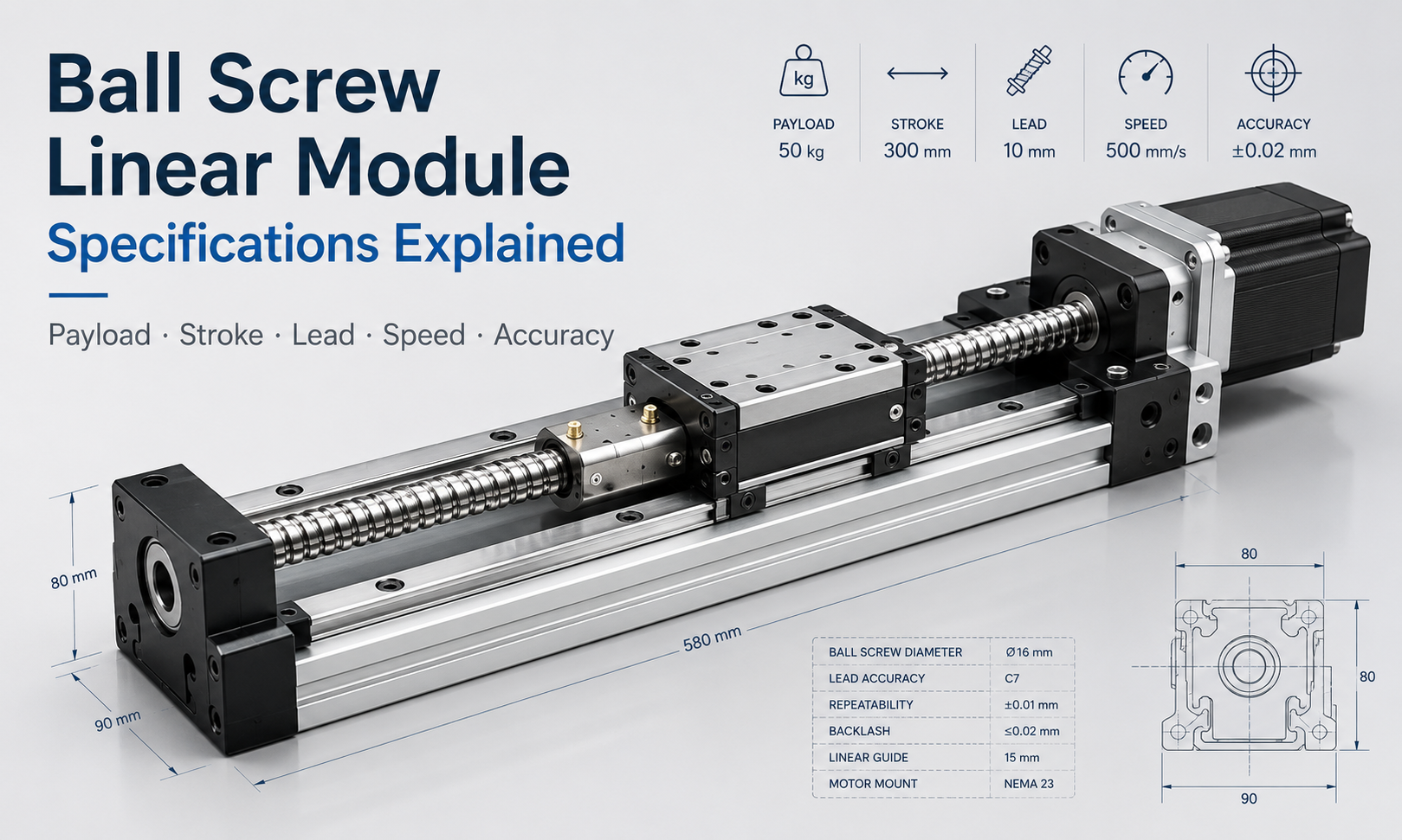
Ball screw linear modulesare widely used in precision automation equipment because they combine accurate positioning, high axial rigidity, efficient power transmission and reliable servo control. However, selecting a suitable module requires more than checking only the payload or stroke.
Payload, stroke, screw diameter, lead, maximum speed, acceleration, positioning accuracy, repeatability, axial load, allowable moment and motor power are closely related. A change in one parameter may affect several other performance indicators.
This guide explains the main specifications of a ball screwlinear module, how these parameters influence actual machine performance and what engineers should consider during module selection.
What Are Ball Screw Linear Module Specifications?
Ball screw linear module specifications describe the mechanical size, motion performance, load capacity and control requirements of the module. These values help engineers determine whether a particular model can safely and accurately complete the required motion task.
| Specification | Typical Unit | Main Meaning |
|---|---|---|
| Payload | kg or N | Maximum workpiece and fixture weight supported by the carriage |
| Stroke | mm | Available linear travel of the carriage |
| Screw Diameter | mm | Nominal diameter of the ball screw shaft |
| Lead | mm/rev | Linear travel produced by one screw revolution |
| Maximum Speed | mm/s | Highest permitted linear operating speed |
| Acceleration | m/s² or G | Rate at which the carriage changes speed |
| Positioning Accuracy | mm | Difference between the commanded and actual position |
| Repeatability | mm | Ability to return to the same position repeatedly |
| Axial Load | N | Force acting along the ball screw axis |
| Allowable Moment | N·m | Maximum permitted overturning or twisting moment |
| Motor Power | W or kW | Motor capacity required to move and accelerate the load |
1. Payload Capacity
Payload is one of the first specifications considered when selecting a ball screw linear module. It normally refers to the total moving mass installed on the carriage, including the workpiece, fixture, tooling, sensors, cables and any additional mechanical components.
The listed payload should not be interpreted as the recommended operating load under every condition. Actual capacity depends on:
- Horizontal or vertical installation
- Load center position
- Acceleration and deceleration
- Stroke length
- Operating speed
- External process forces
- Required service life
- Allowable moment of the guide system
A module carrying a centered load at low speed on a horizontal axis may support more mass than the same module operating vertically with rapid acceleration. Therefore, payload should always be checked together with axial force and moment load.
Static Payload and Dynamic Payload
Static payload describes the load that the module can support while stationary. Dynamic payload refers to the load that can be moved repeatedly under specified speed and acceleration conditions.
For automated equipment, dynamic load capacity is usually more important because acceleration produces additional inertia force:
Inertia force = Moving mass × Acceleration
The ball screw, bearings, guide blocks and motor must withstand both the payload and the dynamic forces generated during operation.
2. Stroke
Stroke is the effective distance through which the carriage can travel. It should not be confused with the overall module length. The total length of a ball screw linear module also includes the carriage, end supports, motor mount, safety clearance and structural components.
When determining the required stroke, engineers should consider:
- Actual workpiece travel
- Tool approach and return distance
- Sensor activation area
- Deceleration distance
- End safety margin
- Future process adjustment
Choosing a stroke equal to the exact working distance can leave insufficient space for deceleration or mechanical tolerance. A reasonable safety allowance should therefore be added.
How Stroke Affects Other Specifications
A longer stroke may reduce the permissible screw rotational speed because of critical-speed limitations. It may also reduce the allowable axial compression load due to screw buckling risk.
For long-stroke applications, engineers should verify:
- Ball screw critical speed
- Screw support configuration
- Screw diameter
- Maximum operating speed
- Vertical compression load
- Potential screw vibration
When very long travel and very high speed are required simultaneously, a timing belt or gear rack linear module may be more suitable than a conventional ball screw design.
3. Ball Screw Diameter
Screw diameter is the nominal shaft diameter of the ball screw. It has a direct influence on axial rigidity, load capacity, critical speed and resistance to buckling.
A larger screw diameter generally provides:
- Higher axial load capacity
- Greater axial rigidity
- Better resistance to compression buckling
- Higher permissible rotational speed for a given length
- Improved suitability for heavy-duty operation
However, a larger screw also increases rotating inertia, module size, weight and cost. It may require a larger motor to achieve the same acceleration.
The correct screw diameter should therefore be selected based on load, stroke, speed, acceleration and required rigidity rather than choosing the largest available diameter.
4. Ball Screw Lead
Ball screw lead is the linear distance traveled by the nut during one complete revolution of the screw. For example, a 10 mm lead moves the carriage 10 mm for each screw revolution.
Lead strongly affects speed, thrust, control resolution and motor torque requirements.
Small-Lead Ball Screws
A smaller lead generally provides:
- Higher mechanical reduction
- Greater linear thrust for the same motor torque
- Finer theoretical positioning resolution
- Better suitability for low-speed precision motion
The main limitation is that the screw must rotate faster to achieve the same linear speed.
Large-Lead Ball Screws
A larger lead generally provides:
- Higher linear travel per revolution
- Higher achievable linear speed at the same screw speed
- Lower required screw rotational speed
- Better suitability for fast transfer motion
However, a larger lead requires more motor torque to generate the same linear thrust and may provide coarser theoretical resolution if the motor and encoder configuration remain unchanged.
Lead and Linear Speed
The theoretical linear speed can be calculated from screw speed and lead:
Linear speed = Screw rotational speed × Screw lead ÷ 60
When screw speed is expressed in revolutions per minute and lead is expressed in millimeters per revolution, the result is in millimeters per second.
The calculated speed must still remain below the module’s permitted maximum speed and the ball screw’s critical-speed limit.
5. Maximum Speed
Maximum speed is the highest linear speed at which the module is permitted to operate under specified conditions. It is influenced by more than motor speed.
Important limiting factors include:
- Ball screw lead
- Screw rotational speed
- Screw diameter and unsupported length
- Bearing support arrangement
- Lubrication condition
- Guide block capability
- Payload
- Vibration and resonance
- Motor torque at high rotational speed
The motor may be capable of rotating faster than the safe speed of the screw. Therefore, the motor speed limit should never be used as the only basis for calculating maximum module speed.
Continuous operating speed may also need to be lower than the short-duration maximum speed, especially in high-duty-cycle equipment.
6. Acceleration
Acceleration determines how quickly the carriage reaches the commanded speed. Higher acceleration can reduce cycle time, but it also increases inertia force, motor torque demand, structural vibration and guide moment load.
The required linear driving force can be estimated as:
Total driving force = Acceleration force + Friction force + External process force + Gravity force
Gravity force must be included for vertical or inclined installations.
High acceleration applications require careful evaluation of:
- Total moving mass
- Motor peak torque
- Coupling capacity
- Ball screw dynamic load
- Guide block moment capacity
- Machine frame rigidity
- Stopping distance
- Settling time after positioning
A module may be able to carry a particular load at low acceleration but become unsuitable when the same load must be accelerated rapidly.
7. Positioning Accuracy
Positioning accuracy describes how closely the actual carriage position matches the commanded position over the working stroke.
Positioning error may result from:
- Ball screw lead error
- Backlash
- Elastic deformation
- Guide installation error
- Thermal expansion
- Coupling deformation
- Motor and encoder resolution
- Controller tuning
- Machine base deformation
For long-stroke precision applications, accumulated lead error may become more important than local repeatability. Some systems use laser calibration or controller compensation to reduce systematic positioning error.
Positioning accuracy should always be evaluated across the required working distance rather than at only one test point.
8. Repeatability
Repeatability is the ability of the carriage to return to the same commanded position repeatedly under the same operating conditions.
A module can have excellent repeatability while still having a measurable absolute positioning error. For example, the carriage may consistently stop at the same location, but that location may be slightly offset from the commanded coordinate.
Repeatability is particularly important for:
- Pick-and-place operations
- Automated assembly
- Dispensing
- Screw fastening
- Loading and unloading
- Vision inspection positioning
- Repeated welding or processing operations
Repeatability can be affected by mechanical clearance, preload condition, temperature change, servo tuning, sensor stability and structural rigidity.
9. Axial Load
Axial load is the force acting along the movement direction of the ball screw. It is not necessarily the same as payload.
For a horizontal axis, payload weight mainly acts on the linear guide, while the ball screw primarily generates the force required to accelerate the mass and overcome friction or process resistance.
For a vertical axis, the ball screw must also support the gravity force of the moving mass. The axial force may be estimated as:
Vertical axial force = Moving mass × Gravitational acceleration + Acceleration force + External force
The selected ball screw should be checked for:
- Dynamic load rating
- Static load rating
- Expected service life
- Maximum compressive load
- Buckling resistance
- Support bearing capacity
Vertical applications should also consider a brake motor, counterbalance or mechanical falling-prevention device.
10. Allowable Moment
Allowable moment describes the module’s ability to resist loads acting at a distance from the carriage center. An offset payload generates an overturning moment even when the total mass is within the listed payload capacity.
Linear modules are commonly evaluated for moments around three axes:
- Pitching moment:forward or backward overturning
- Yawing moment:left or right rotation in the horizontal plane
- Rolling moment:twisting around the travel axis
Moment can be calculated approximately as:
Moment = Force × Distance from the load center
Reducing the distance between the payload center of gravity and the carriage surface can significantly reduce moment load.
For large fixtures, cantilever structures or wide workpieces, engineers may need a wider module, dual guide rails, two synchronized modules or an external support guide.
11. Motor Power
Motor power must be sufficient to accelerate the moving mass, overcome friction, resist external process forces and maintain the required speed.
Motor selection should not be based only on rated power. Important motor parameters include:
- Rated torque
- Peak torque
- Rated speed
- Maximum speed
- Rotor inertia
- Encoder resolution
- Brake requirement
- Duty cycle
- Motor-to-load inertia ratio
The approximate torque required to generate linear force through a ball screw can be estimated from the axial force, screw lead and transmission efficiency:
Motor torque ≈ Axial force × Screw lead ÷ Ball screw transmission factor
A complete calculation should also include the acceleration torque of the screw, coupling and motor rotor.
Oversizing the motor excessively is not always beneficial. A very large motor increases cost, rotor inertia and mechanical stress. The objective is to provide adequate rated and peak torque with a reasonable safety margin.
How Ball Screw Module Specifications Affect Each Other
The specifications of a ball screw linear module should be evaluated as a complete system.
| Design Change | Possible Benefit | Possible Trade-Off |
|---|---|---|
| Increase screw diameter | Higher rigidity and axial capacity | Greater inertia, size and motor demand |
| Increase screw lead | Higher linear speed | Higher torque demand and lower mechanical reduction |
| Increase stroke | Larger working range | Lower critical speed and buckling resistance |
| Increase acceleration | Shorter cycle time | Higher inertia force, vibration and peak torque |
| Increase payload | Ability to move heavier tooling | Reduced acceleration and increased guide load |
| Increase preload | Higher rigidity and lower clearance | Higher friction and heat generation |
Example Specification Selection Process
Consider an automated assembly axis with the following requirements:
- Horizontal installation
- Effective travel of 600 mm
- Total moving mass of 25 kg
- Maximum speed of 500 mm/s
- Acceleration of 3 m/s²
- High repeatability requirement
- Offset tooling installed on the carriage
The engineer should not simply choose a module with a payload rating above 25 kg. The selection process should include:
- Add safety clearance to the 600 mm working travel.
- Calculate acceleration force from the 25 kg moving mass.
- Add friction and any process force.
- Select a suitable screw lead based on speed and motor speed.
- Check screw critical speed at the selected stroke.
- Calculate the moment generated by the offset tooling.
- Verify guide block load and moment capacity.
- Check required motor rated and peak torque.
- Confirm positioning accuracy and repeatability.
- Evaluate duty cycle, lubrication and expected service life.
This system-level method reduces the risk of selecting a module that satisfies one specification but fails under actual operating conditions.
Ball Screw Linear Module Specification Checklist
Before confirming a model, provide the manufacturer with the following information:
- Horizontal, vertical or inclined installation
- Required effective stroke
- Total moving mass
- Payload center-of-gravity position
- Required maximum speed
- Required acceleration and deceleration
- Required positioning accuracy
- Required repeatability
- External axial or process force
- Operating cycle and daily running time
- Motor type and control system
- Environmental conditions
- Expected service life
Providing complete application data allows the module manufacturer to verify the ball screw, guide rail, bearings, motor and structural configuration together.
Frequently Asked Questions
Is payload the same as axial load?
No. Payload normally refers to the moving mass installed on the carriage, while axial load is the force acting along the ball screw axis. They are related but should be calculated separately.
Does a larger ball screw lead always provide higher speed?
A larger lead increases linear travel per revolution, but actual speed is still limited by motor torque, screw critical speed, bearing capability, payload and module structure.
What is the difference between positioning accuracy and repeatability?
Positioning accuracy measures the difference between the commanded and actual position. Repeatability measures how consistently the module returns to the same position during repeated movements.
Can the maximum payload operate at maximum speed and acceleration?
Not necessarily. Maximum payload, maximum speed and maximum acceleration may be specified under different conditions. Their combined operating limits must be confirmed with the manufacturer.
Why does a longer stroke reduce maximum speed?
A longer ball screw has a lower critical rotational speed and is more susceptible to vibration or bending. Increasing screw diameter or changing the support configuration may improve the permissible speed.
Conclusion
Ball screw linear module specifications must be considered as an interconnected system. Payload, stroke, screw diameter, lead, speed, acceleration, accuracy, repeatability, axial load, allowable moment and motor power all influence the final performance of the motion axis.
A reliable selection should be based on actual installation direction, moving mass, load center, operating cycle, speed profile, precision requirement and environmental conditions. Engineers should also avoid assuming that every maximum specification can be achieved simultaneously.
By evaluating both mechanical and motion-control requirements, users can select a ball screw linear module that provides suitable accuracy, rigidity, speed, load capacity and service life for the application.
