 English

Aball screw linear moduleis a precision motion system that converts the rotary motion of a motor into controlled linear movement. Its positioning accuracy, load capacity, rigidity, operating speed and service life depend not only on the ball screw itself, but also on the coordinated performance of the nut, recirculating balls, linear guides, bearings, coupling, carriage, sensors and lubrication components.
Understanding the function of each component helps engineers select the correct module, diagnose mechanical problems and maintain reliable motion performance throughout the equipment life cycle. This guide explains the main components of a ball screw linear module and how they work together.
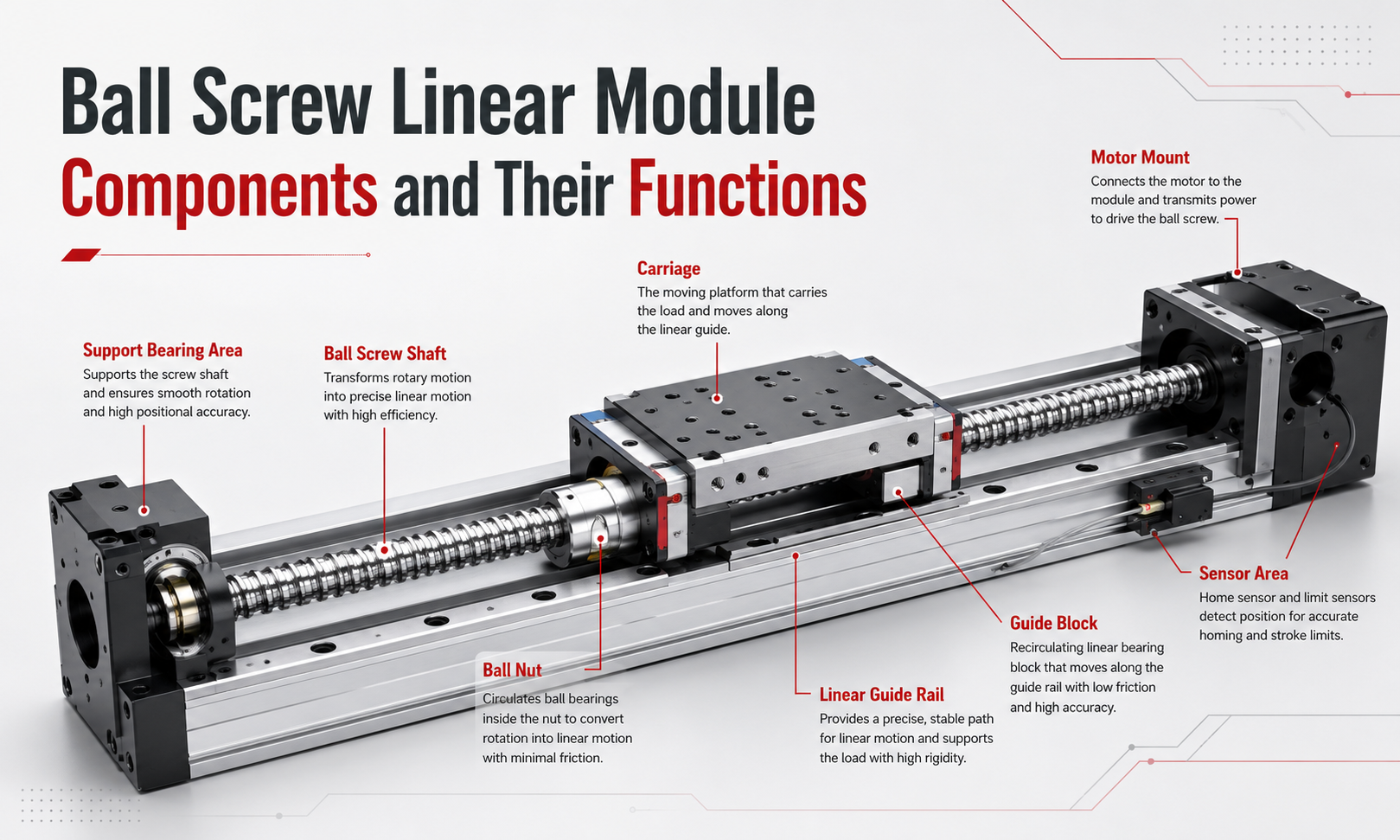
Ball Screw Linear Module Component Overview
A typical ball screw linear module contains a drive system, a guiding system, a supporting structure and a control feedback system. Each group performs a different function.
- Drive components:ball screw shaft, ball nut, recirculating balls and coupling.
- Guiding components:linear guide rails and guide blocks.
- Support components:bearings, aluminum base, carriage and motor mount.
- Control components:limit sensors, origin sensors and optional position feedback devices.
- Maintenance components:grease ports, lubrication lines, seals and protective covers.
The ball screw generates linear motion, while the linear guide supports the moving load and controls its travel direction. Bearings stabilize the rotating screw, the coupling transfers motor torque and the sensors provide travel-limit and reference-position signals.
| Component | Main Function | Influence on Module Performance |
|---|---|---|
| Ball screw shaft | Converts rotary motion into linear movement | Speed, thrust, lead accuracy and travel repeatability |
| Ball nut | Moves along the screw shaft | Backlash, rigidity and transmission efficiency |
| Recirculating balls | Reduce friction between the screw and nut | Smoothness, efficiency, wear and service life |
| Linear guide | Defines the linear travel path | Straightness, rigidity and moment-load capacity |
| Guide block | Supports and carries the moving carriage | Load distribution and motion stability |
| Support bearings | Support and locate the rotating screw | Axial rigidity, vibration and critical speed |
| Coupling | Connects the motor shaft to the ball screw | Torque transmission and alignment tolerance |
| Carriage | Provides the mounting surface for the payload | Structural rigidity and load installation |
| Motor mount | Positions and supports the drive motor | Shaft alignment and drive stability |
| Sensors | Detect origin and travel limits | Machine safety and automatic positioning |
| Lubrication components | Supply lubricant to rolling contact surfaces | Friction, temperature, noise and component life |
1. Ball Screw Shaft
The ball screw shaft is the main transmission component of the module. It has a precisely machined helical raceway along its surface. When the motor rotates the shaft, the ball nut travels forward or backward according to the direction of rotation.
Main Functions of the Ball Screw Shaft
- Convert motor rotation into linear displacement.
- Transmit axial thrust to the moving carriage.
- Determine linear travel per motor revolution.
- Influence positioning accuracy and maximum operating speed.
The distance the nut moves during one complete screw revolution is called thelead. A smaller lead generally provides higher mechanical resolution and greater thrust for the same motor torque. A larger lead can produce higher linear speed but may require more motor torque and careful control of acceleration.
Ball screw shafts are commonly manufactured by grinding or precision rolling. Ground ball screws are normally selected for applications requiring tighter lead accuracy and more demanding positioning performance. Rolled ball screws provide a practical balance between accuracy and cost for general automation equipment.
Important Ball Screw Shaft Parameters
- Nominal shaft diameter
- Screw lead
- Lead accuracy grade
- Effective stroke
- Root diameter
- Dynamic and static load rating
- Critical rotational speed
- Buckling resistance
For long-stroke modules, shaft diameter and rotational speed require particular attention. A long, slender screw rotating too quickly may experience vibration or whipping. The screw must also have sufficient compressive strength when it is used in vertical or high-thrust applications.
2. Ball Nut
The ball nut surrounds the screw shaft and contains matching helical raceways. Recirculating steel balls roll between the screw and nut raceways, allowing the nut to travel with much lower friction than a conventional sliding screw.
Main Functions of the Ball Nut
- Transfer axial force between the screw shaft and carriage.
- Contain and guide the recirculating balls.
- Provide the mechanical connection between the drive system and moving platform.
- Control axial clearance and transmission rigidity.
The nut is usually connected to the carriage through a nut housing or flange. This connection must be rigid and accurately aligned. Improper mounting can create uneven loading, excessive friction, abnormal noise and premature wear.
Ball Nut Preload
Preload removes or reduces axial clearance between the ball screw and nut. It improves rigidity, reversing accuracy and repeatability, especially when the module frequently changes direction.
However, excessive preload increases friction, motor load and operating temperature. The correct preload level should therefore be selected according to the required accuracy, load, speed and duty cycle.
Common preload arrangements include oversized-ball preload, offset-lead preload and double-nut preload. Compact industrial modules often use a factory-adjusted single nut to balance size, rigidity and cost.
3. Recirculating Balls
Recirculating balls are precision steel balls located between the screw shaft and ball nut. They roll along the loaded raceway, enter a return path and circulate back to the beginning of the load zone.
This recirculation system allows continuous nut movement without the balls leaving the assembly.
Functions of the Recirculating Balls
- Reduce sliding friction between the screw and nut.
- Transmit axial loads through rolling contact.
- Improve mechanical efficiency.
- Support smooth acceleration and deceleration.
- Reduce wear compared with sliding screw mechanisms.
The ball diameter, quantity, material quality and raceway geometry affect load capacity and running smoothness. Contamination, inadequate lubrication or damaged return components can interrupt ball circulation and cause vibration, noise or jamming.
Ball return systems may use internal deflectors, end caps, return tubes or other circulation structures. The selected design depends on nut dimensions, lead, speed and manufacturing requirements.
4. Linear Guide
The linear guide controls the movement direction of the carriage and supports external loads. Although the ball screw generates axial movement, it should not be used as the primary component for carrying radial or moment loads.
The guide rail absorbs these forces and keeps the moving platform aligned throughout the stroke.
Main Functions of the Linear Guide
- Provide a straight and repeatable motion path.
- Support vertical, horizontal and lateral loads.
- Resist pitch, yaw and roll moments.
- Protect the ball screw from excessive side loading.
- Maintain carriage stability during acceleration.
Guide rail straightness, mounting accuracy and base rigidity directly affect module accuracy. Even a high-precision ball screw cannot deliver stable positioning if the guide rail is installed on a distorted or poorly machined mounting surface.
Some compact modules use one profiled guide rail with two guide blocks. Wider or heavier-duty modules may use two parallel rails to improve moment-load capacity and platform stability.
5. Guide Block
The guide block, also called a linear bearing block or carriage block, travels along the linear guide rail. It contains rolling elements that circulate inside the block as it moves.
Main Functions of the Guide Block
- Connect the guide rail to the moving carriage.
- Transfer payload forces into the module base.
- Distribute radial and moment loads.
- Maintain low-friction linear motion.
The number, size and spacing of guide blocks determine how effectively the module resists moment loads. Increasing the distance between blocks generally improves resistance to pitch and yaw moments.
Guide blocks may also include seals, scrapers and lubrication ports. These features help prevent dust and particles from entering the rolling raceways.
During assembly, the guide blocks and ball nut must be aligned so that neither component is forced to compensate for the mounting error of the other. Misalignment can create internal stress and uneven wear.
6. Support Bearings
Support bearings hold the ball screw in the correct axial and radial position while allowing it to rotate. Most ball screw linear modules use a fixed-end and supported-end arrangement.
Fixed-End Bearing Support
The fixed end usually uses matched angular-contact bearings or a precision support-bearing unit. It controls the axial position of the screw and resists thrust in both directions.
The fixed-end support has a major influence on axial rigidity, positioning stability and rotational accuracy.
Supported or Floating-End Bearing
The opposite end usually uses a radial bearing that supports the screw while allowing limited axial thermal expansion. This arrangement prevents the screw from being excessively constrained as its temperature changes.
Functions of the Support Bearings
- Maintain screw-shaft alignment.
- Resist axial transmission forces.
- Reduce screw vibration and radial movement.
- Increase the allowable rotational speed.
- Control axial displacement at the fixed end.
Incorrect bearing preload, loose locknuts or damaged bearings can cause abnormal noise, increased backlash and unstable positioning. Bearing installation should follow the specified tightening sequence and preload requirements.
7. Coupling
The coupling connects the motor shaft to the ball screw shaft. Its main purpose is to transfer torque while accommodating small amounts of angular, parallel or axial misalignment.
Main Functions of the Coupling
- Transfer motor torque to the ball screw.
- Compensate for minor shaft-alignment errors.
- Reduce shock transmission between the motor and screw.
- Protect connected components from excessive assembly stress.
Common coupling types include helical beam couplings, bellows couplings, disc couplings and elastomer couplings. High-precision positioning systems generally require a torsionally rigid coupling with minimal rotational backlash.
A flexible coupling can compensate for small errors, but it should not be used to correct severe misalignment. Large alignment errors increase bearing loads, generate vibration and shorten the service life of the motor and support bearings.
The coupling bore diameter, rated torque, maximum speed and clamping method must match both the motor shaft and ball screw input shaft.
8. Carriage
The carriage is the moving platform on which the payload, fixture, tooling or another linear axis is installed. It connects the ball nut to the guide blocks and transfers the generated linear motion to the external load.
Main Functions of the Carriage
- Provide a rigid payload mounting surface.
- Connect the ball nut and linear guide blocks.
- Distribute load across the guiding components.
- Transfer acceleration and deceleration forces.
- Support multi-axis system integration.
The carriage should have sufficient thickness and rigidity to prevent deformation under load. A flexible carriage can reduce positioning accuracy even when the screw and guide components are correctly selected.
Threaded holes, locating holes, dowel-pin holes and reference surfaces are often machined into the carriage to simplify equipment installation. Payloads should be mounted evenly and as close as practical to the carriage surface to reduce overturning moments.
9. Motor Mount
The motor mount supports the servo motor or stepper motor and maintains its alignment with the ball screw. It is normally connected to the fixed-end bearing housing or module base.
Main Functions of the Motor Mount
- Position the motor relative to the ball screw.
- Maintain coupling alignment.
- Resist motor reaction torque.
- Provide a rigid interface between the motor and module.
- Simplify motor installation and replacement.
A poorly machined or flexible motor mount may cause coupling misalignment, vibration and inconsistent positioning. The mounting dimensions must match the motor flange, pilot diameter, shaft diameter and bolt pattern.
Adapter plates may be used when different motor brands or frame sizes need to be installed on the same module platform.
10. Sensors
Sensors provide position-reference and travel-limit signals to themotion controller. They help prevent the carriage from moving beyond its safe mechanical range and allow the system to establish a repeatable home position.
Common Sensors in a Ball Screw Linear Module
- Home sensor:establishes the machine reference position during homing.
- Positive limit sensor:detects the maximum travel position in the positive direction.
- Negative limit sensor:detects the maximum travel position in the negative direction.
- Additional position sensor:confirms the carriage has reached a specified process position.
Common sensing technologies include inductive proximity sensors, photoelectric sensors, magnetic sensors and mechanical limit switches.
Sensor placement must allow sufficient deceleration distance before the carriage reaches a mechanical stop. Software travel limits should normally be configured inside the physical limit-sensor positions to create an additional safety margin.
Sensor cables should be protected from repeated bending, oil, cutting fluids and electrical interference. Proper cable routing is especially important in high-cycle automation systems.
11. Lubrication Components
Lubrication components deliver grease or oil to the ball screw raceways, ball nut and linear guide blocks. Proper lubrication reduces friction, limits temperature rise, prevents corrosion and extends component service life.
Typical Lubrication Components
- Grease nipples
- Lubrication ports
- Oil or grease lines
- Distribution blocks
- Automatic lubrication units
- Seals and scrapers
Lubrication intervals depend on travel distance, speed, load, operating environment, duty cycle and lubricant type. High-speed, high-load or contaminated applications normally require more frequent inspection and lubrication.
Too little lubricant causes increased friction, wear and noise. Excessive lubricant can also increase resistance and operating temperature, particularly at high speed. Only compatible lubricant in the specified quantity should be used.
Mixing incompatible grease types may reduce lubrication performance. Before changing lubricant, the previous lubricant should be removed according to the component manufacturer’s recommendations.
How the Components Work Together
During operation, the motor rotates the coupling, which transfers torque to the ball screw shaft. The rotating screw causes the ball nut to move linearly through the rolling action of the recirculating balls.
The ball nut is connected to the carriage, so its movement drives the carriage along the linear guide. The guide blocks support the payload and absorb radial and moment loads, while the support bearings keep the screw correctly positioned during rotation.
The controller uses feedback from the motor encoder and module sensors to control position, velocity and acceleration. Lubrication components maintain a protective film between the rolling surfaces, while seals and covers reduce contamination.
Reliable motion therefore depends on the entire mechanical chain:
Motor → Coupling → Ball Screw Shaft → Recirculating Balls → Ball Nut → Carriage → Payload
At the same time, the linear guide, guide blocks, support bearings, sensors and lubrication system maintain alignment, stability, safety and service life.
Component Selection Factors
Ball screw linear module components should be selected as a complete system rather than as isolated parts. Important engineering factors include:
Load Capacity
The ball screw, nut, guide blocks, bearings and carriage must all withstand the required static load, dynamic load and acceleration force. The guide system must also resist any pitch, yaw and roll moments created by an offset payload.
Required Speed
Maximum speed is affected by screw lead, motor speed, screw diameter, screw length, support-bearing arrangement and critical rotational speed. High-speed applications may require a larger lead or alternative drive structure.
Positioning Accuracy
Accuracy depends on screw lead error, backlash, preload, bearing rigidity, guide straightness, base machining and controller compensation. Selecting only a high-accuracy screw does not guarantee high system accuracy.
Stroke Length
Longer strokes increase the risk of screw whipping, buckling and thermal expansion. The required stroke must be evaluated together with rotational speed and axial load.
Duty Cycle
High-frequency continuous operation creates more heat and requires careful consideration of lubrication, preload, motor sizing and component service life.
Operating Environment
Dust, chips, moisture, chemicals and cleanroom requirements affect the selection of covers, seals, lubrication systems and corrosion-resistant materials.
Installation Orientation
Vertical installation requires consideration of gravity load, motor holding torque, brake selection and protection against uncontrolled downward movement during power loss.
Ball Screw Linear Module Component Maintenance
Regular inspection helps prevent small mechanical problems from developing into positioning failure or component damage.
Recommended Inspection Items
- Check the ball screw and guide rails for contamination.
- Inspect lubrication condition and replenish grease when required.
- Check the coupling for looseness, cracking or deformation.
- Inspect bearing noise and abnormal temperature rise.
- Verify carriage mounting bolts and payload fasteners.
- Check sensor position, wiring and switching condition.
- Observe backlash, vibration and positioning repeatability.
- Inspect protective covers, seals and scrapers for damage.
Common Signs of Component Problems
| Symptom | Possible Components | Typical Causes |
|---|---|---|
| Increased positioning error | Ball nut, bearings, coupling | Backlash, loose connection or wear |
| Abnormal mechanical noise | Ball screw, guide blocks, bearings | Insufficient lubrication, contamination or damage |
| Motor overload | Ball nut, guide rail, coupling | Misalignment, excessive preload or obstruction |
| Carriage vibration | Guide system, coupling, screw support | Loose mounting, resonance or screw whipping |
| Irregular motion | Ball circulation system, guide blocks | Contamination, damaged raceways or lubrication failure |
| Incorrect homing | Home sensor, sensor bracket, wiring | Sensor movement, cable fault or incorrect controller settings |
The module should be stopped and inspected when severe noise, jamming, rapid temperature rise or sudden positioning changes occur. Continuing operation under abnormal conditions may damage the screw raceways, nut, guide blocks or bearings.
Which Components Most Affect Accuracy?
The ball screw and ball nut have a direct influence on lead accuracy, backlash and axial rigidity. However, total module accuracy also depends on several supporting components.
- The support bearings control axial movement of the screw.
- The coupling affects rotational transmission and alignment.
- The linear guide determines travel straightness.
- The carriage and base influence structural deformation.
- The motor encoder and control system determine command resolution and feedback performance.
For this reason, system-level accuracy should be evaluated at the carriage or payload mounting surface rather than inferred only from the ball screw accuracy grade.
Which Components Carry the Load?
The axial driving force is transmitted through the ball screw shaft, recirculating balls and ball nut. External radial and moment loads should primarily be carried by the linear guide rails and guide blocks.
The carriage distributes the payload forces to the guide blocks, while the module base transfers these forces into the machine frame. Proper mounting is necessary to prevent the ball screw from being exposed to excessive side loads.
Why Component Matching Is Important
A module may contain individually high-quality components but still perform poorly if they are not correctly matched. For example:
- A high-lead screw paired with an undersized motor may not produce enough acceleration force.
- A rigid preloaded nut combined with a flexible base may not deliver stable positioning.
- A high-speed screw with inadequate bearing support may experience vibration.
- A large payload mounted far above a narrow carriage may exceed the guide system’s moment capacity.
- A precision screw installed with poor alignment may wear rapidly and generate excessive torque.
Correct module design therefore requires coordinated selection of the transmission, guiding, support, drive and control components.
Frequently Asked Questions
What are the main components of a ball screw linear module?
The main components include the ball screw shaft, ball nut, recirculating balls, linear guide rail, guide blocks, support bearings, coupling, carriage, motor mount, sensors and lubrication components.
What is the function of the ball nut?
The ball nut moves along the rotating screw shaft and transfers axial force to the carriage. It also contains the recirculating balls and controls the clearance between the screw and nut.
Why does a ball screw use recirculating balls?
The balls replace sliding contact with rolling contact, reducing friction and allowing efficient, smooth and accurate linear movement. The recirculation path continuously returns the balls to the loaded raceway.
Does the ball screw support the payload?
The ball screw mainly transmits axial driving force. Radial loads and moment loads should be supported by the linear guide rails and guide blocks.
What is the purpose of the fixed-end bearing?
The fixed-end bearing controls the axial position of the ball screw and resists thrust in both directions. It is important for transmission rigidity and positioning stability.
Why is a coupling required?
The coupling transfers torque from the motor to the ball screw and accommodates small shaft-alignment errors. A torsionally rigid, low-backlash coupling is commonly used for precision motion.
How does preload affect the ball nut?
Preload reduces axial clearance and improves rigidity and reversing accuracy. Excessive preload, however, increases friction, motor load and operating temperature.
How often should the ball screw module be lubricated?
The lubrication interval depends on speed, load, travel distance, duty cycle and operating environment. The module manufacturer’s lubrication instructions should be followed, with more frequent inspection in dusty, high-speed or high-load conditions.
What causes abnormal noise in a ball screw module?
Common causes include insufficient lubrication, contaminated raceways, damaged bearings, coupling misalignment, loose fasteners, damaged ball-return components and excessive preload.
Can individual module components be replaced?
Many components can be replaced, but the replacement must match the original dimensions, preload, accuracy grade and installation requirements. After replacing the ball screw, nut, bearings or guide components, alignment and positioning accuracy should be checked again.
Conclusion
A ball screw linear module is a coordinated motion system rather than a single transmission component. The ball screw shaft, ball nut and recirculating balls generate efficient linear movement. The guide rails and guide blocks support the payload, while the bearings, coupling, carriage and motor mount maintain rigidity and alignment.
Sensors protect the travel range and establish the reference position, while lubrication components reduce friction and wear. Correct component selection, accurate assembly and regular maintenance are all necessary to achieve stable positioning accuracy, long service life and reliable operation.
When selecting a ball screw linear module, engineers should evaluate the entire component system according to load, stroke, speed, accuracy, duty cycle, installation orientation and environmental conditions.
