 English

Robots are highly flexible inside their working envelope, but many automation systems need motion beyond that envelope. A robot may need to travel several meters along a production line, a pick-and-place cell may need coordinated XYZ movement, or an AGV docking station may need a compact linear axis to position a fixture or end effector.
This is wherelinear modules in roboticsbecome important. They can act as robot travel axes, Cartesian robot structures, gantry axes, palletizing axes or secondary positioning units that extend the reach and flexibility of the main robot.
This guide explains howlinear modulesare used in robotic automation, what each application demands from the motion system, and how engineers should evaluate speed, payload, stiffness, synchronization, safety and integration before selecting a module.
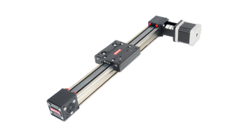
Why Robots Need Linear Axes
A six-axis robot provides excellent angular freedom, but its reach is limited by its arm geometry. Adding a linear axis allows the entire robot or end effector to move through a larger working area.
Typical reasons to add a linear module include:
- Extending robot reach along a machine or production line
- Serving multiple stations with one robot
- Reducing the need for several fixed robots
- Creating long-travel pick-and-place motion
- Building Cartesian or gantry robot structures
- Moving end effectors independently from the robot arm
- Positioning fixtures, trays, sensors or tools
System-level rule:a robot linear axis should be sized from the total moving system, not only the workpiece. Robot mass, tooling, cables, fixtures and acceleration all contribute to the load.
Robot Seventh Axes: Extending the Working Envelope
A robot seventh axis is a linear travel axis that carries the robot base along a rail or module. It allows one robot to access several machines, pallets or work areas.
Common applications include:
- Machine tending
- Welding cells
- Large-part assembly
- Material handling
- Inspection
- Multi-station loading and unloading
Why robot mass changes the mechanical design
The linear axis must carry the complete robot, not only the payload in the robot gripper. A robot with a relatively modest payload can still have a large base mass and generate substantial dynamic moments during arm movement.
The linear axis should therefore be checked for:
- Total robot and tooling mass
- Center-of-gravity position
- Dynamic overturning moments
- Acceleration of the rail axis
- Emergency-stop loads
- Base and frame stiffness
Long travel changes the preferred drive
Very long robot travel axes often favor rack-and-pinion or other scalable long-stroke transmissions because screw-based systems become increasingly limited by critical speed and support requirements as length grows.
For shorter, higher-precision robot travel axes, ball screw or other compact linear module structures may still be appropriate.
Pick-and-Place Cells: Cycle Time Is More Than Maximum Speed
Pick-and-place automation is one of the most common applications for linear modules. The system may use a single axis, XY table, XZ arrangement or full XYZ Cartesian structure.
These systems typically value:
- High acceleration
- Short move time
- Repeatable stop positions
- Low moving mass
- Fast direction reversal
- Stable end-effector motion
Why acceleration can matter more than top speed
If the stroke is short, the axis may never remain at maximum velocity for long. In that case, acceleration and deceleration dominate cycle time.
A module with a high catalog maximum speed but poor dynamic behavior may not outperform a slightly slower axis that accelerates, settles and reverses more efficiently.
End-effector mass must be included
The moving load includes the gripper, vacuum tooling, sensors, cables and the picked product. If the gripper is mounted far from the carriage, the resulting moment load may become more important than the payload itself.
XYZ Cartesian Robots and Gantry Systems
Linear modules can be combined into Cartesian robot structures where each axis controls motion in one linear direction.
Typical configurations include:
- XY positioning tables
- XZ pick-and-place units
- XYZCartesian robots
- Dual-X gantry systems
- Long-span palletizing gantries
Lower axes carry the upper axes
In an XYZ system, the X axis may need to move the Y axis, Z axis, motors, end effector, cables and workpiece together.
This creates a hierarchical sizing problem:
Size from the tool outward.The Z axis carries the tool, the Y axis carries Z plus the tool, and the X axis may carry the complete YZ assembly.
Crossbeam stiffness matters
In gantry systems, the beam between two supports can deflect under the weight of the Y or Z carriage and during acceleration. This affects positioning, vibration and settling time.
A wide gantry should therefore be evaluated as a structural system, not simply as two strong linear modules connected by an aluminum beam.
Dual-Drive Gantries Require Synchronization
Large gantries may use two parallel driven X axes. This improves load distribution and supports wide crossbeams, but it introduces synchronization requirements.
If the two sides do not move together, the bridge can rack or twist.
Synchronization can be mechanical or electronic
Mechanical synchronization may use a common shaft or transmission to link both sides. Electronic synchronization uses two motors and coordinates their position through the control system.
Electronic dual-drive systems require careful consideration of:
- Homing strategy
- Position matching between both sides
- Encoder feedback
- Servo tuning
- Frame stiffness
- Emergency-stop behavior
A dual-drive gantry should never rely on control synchronization to compensate for poor mechanical alignment.
Palletizing: Reach, Payload and Repetition
Palletizing automation often requires long travel, large working envelopes and repeated movement of moderate or heavy payloads.
Linear modules can be used to:
- Extend a robot along multiple pallet positions
- Create Cartesian palletizing systems
- Move layer-handling tooling
- Position empty pallets or slip sheets
- Serve several conveyors from one robot
Duty cycle matters
Palletizing systems can operate for many hours with thousands of repeated cycles. The module should be checked for bearing life, drive wear, lubrication, motor thermal loading and cable-carrier life—not only peak payload.
Large payloads create moment loads
Boxes, trays or grippers can create substantial overhung load. Wide tooling may generate pitch and yaw moments even when the total mass is within the module's nominal payload rating.
Linear Modules for Robot End-Effector Motion
Not every linear axis needs to move the robot base. Compact modules can be mounted on or near the robot to add a controlled linear degree of freedom to the end effector.
Examples include:
- Adjustable gripper spacing
- Tool extension
- Linear pressing or insertion
- Camera or sensor adjustment
- Part-centering mechanisms
- Variable-pitch handling systems
Keep end-effector axes light
Every kilogram added to the robot wrist reduces available payload margin and increases inertia. Compact, lightweight linear modules are therefore particularly valuable for end-of-arm motion.
Motor mass, cables and brackets should be included in the robot's allowable wrist load and moment calculation.
AGV and AMR Integration: Linear Motion at the Mobile Interface
AGVs and AMRs often transport parts between stations, but the mobile platform may still need a linear positioning mechanism to transfer, align or present the load.
Possible uses include:
- Extending a tray into a machine
- Adjusting docking position
- Lifting or shifting a fixture
- Transferring totes or pallets
- Positioning sensors or connectors
Mobile systems introduce new constraints
An AGV-integrated axis must often deal with limited onboard power, vibration during travel, compact installation space and repeated docking tolerances.
The linear module should be evaluated for:
- Low power consumption
- Mechanical locking or holding where required
- Resistance to transport vibration
- Compact motor arrangement
- Reliable home and limit sensing
- Safe interaction with docking stations
Robot Linear Axis Drive Types
| Drive Type | Typical Robotic Strength | Common Trade-Off |
|---|---|---|
| Ball screw | Precision, rigidity, thrust | Long-stroke high-speed limits |
| Timing belt | High speed, long travel, low moving mass | Lower transmission stiffness |
| Rack and pinion | Very long travel and scalable length | Gear mesh and backlash control |
| Linear motor | High acceleration and direct-drive precision | Higher cost and thermal/control demands |
How to Choose the Drive for a Robotic Axis
Choose ball screw when
The axis needs relatively compact travel, high stiffness, controlled thrust and good positioning performance.
Choose timing belt when
The axis needs longer travel, high speed and rapid pick-and-place movement with moderate precision requirements.
Choose rack and pinion when
The robot must travel several meters or the axis length needs to scale beyond practical screw limits.
Choose linear motor when
The application requires very high acceleration, fast reversing, low transmission backlash and high dynamic positioning performance.
These are engineering starting points, not fixed rules. Final selection depends on load, stroke, speed, accuracy, environment and cost.
Servo Motors Are Common, but Not Always Mandatory
High-cycle robotic axes often use servo motors because they provide closed-loop position control, strong dynamic performance and easy integration with coordinated motion systems.
Servo systems are especially useful when:
- The axis accelerates rapidly
- The robot and linear axis move simultaneously
- Position must be continuously monitored
- Dual-axis synchronization is required
- The machine uses coordinated interpolation
Stepper or closed-loop stepper motors can still be appropriate for simpler indexing or adjustment axes where speed and dynamic demand are lower.
Robot and Linear Axis Control Must Be Coordinated
A robot travel axis can be controlled in several ways depending on the automation architecture.
The axis may be:
- Integrated into the robot controller as an external axis
- Controlled by a PLC ormotion controller
- Operated as an independent positioning axis
- Electronically synchronized with another axis
Integrated external-axis control
When the robot controller treats the linear module as an additional coordinated axis, robot path planning can include base travel. This is useful for welding, processing and applications where the robot and rail must move together.
Independent positioning
For machine tending or pallet transfer, the rail may move to a fixed station, stop, and then allow the robot to perform its task. In this case, simpler sequencing may be sufficient.
Accuracy Requirements Depend on the Robotic Task
Not every robot axis needs the same precision.
| Application | More Important Motion Metric |
|---|---|
| Pick and place | Repeatability and settling |
| Machine tending | Repeatable station positioning |
| Inspection | Position accuracy and geometric stability |
| Welding | Path coordination and structural stiffness |
| Palletizing | Repeatability, payload capacity and long-term durability |
For many robot travel axes, absolute accuracy may be less critical than repeatability because station coordinates can be taught during commissioning. Other applications, such as inspection or process path control, may require tighter absolute performance.
Structural Stiffness Affects Robot Accuracy
A linear module can position its carriage accurately while the robot tool still moves because the frame, rail base or robot pedestal deflects.
Important structural factors include:
- Base flatness
- Rail support spacing
- Robot pedestal stiffness
- Crossbeam deflection
- Tooling overhang
- Floor or machine-frame rigidity
Robot accuracy is a system property.The tool-center position depends on the linear axis, robot structure, mounting frame and end effector together.
Cables and Utilities Can Become a Hidden Load
Robot rails and gantries often carry power cables, encoder cables, pneumatic lines, vacuum tubes and communication cables over long distances.
A cable carrier can introduce:
- Variable drag force
- Additional moving mass
- Side load
- Vibration
- Minimum bend-radius constraints
Cable systems should therefore be included during motor sizing and mechanical layout, not treated as an accessory added after the axis is selected.
Safety Requirements Change With Large Moving Robots
Adding a linear axis increases the robot's working envelope and can create new hazards. The moving rail, robot base and tooling may enter areas that were not reachable by the fixed robot.
Machine design may need to consider:
- Travel limits
- Mechanical end stops
- Safe homing
- Emergency stopping distance
- Guarding and access control
- Safe speed and position monitoring
- Vertical-axis holding
The linear module itself is only one part of the complete machine safety design.
Reliability Matters in High-Cycle Automation
Robotic cells often operate for multiple shifts with repetitive cycles. A linear module that performs well during commissioning must also maintain accuracy and smoothness over long production periods.
Long-term reliability depends on:
- Correct load and moment sizing
- Appropriate acceleration
- Lubrication
- Belt or rack maintenance
- Guide alignment
- Cable-carrier condition
- Environmental contamination
- Preventive inspection
A Practical Robotic Linear Axis Selection Process
- Define the robotic task.Robot rail, pick and place, gantry, palletizing, AGV interface or end-effector motion?
- Calculate the complete moving mass.Include robot, tooling, upper axes and cables.
- Define stroke and working envelope.
- Set cycle time, speed and acceleration.
- Calculate payload and moment loads.
- Select the drive type.
- Check motor torque, speed and inertia.
- Define repeatability and accuracy requirements.
- Check structural stiffness and support.
- Plan cable and utility routing.
- Choose the control architecture.
- Review safety and emergency-stop behavior.
- Verify maintenance access and expected duty cycle.
What QRXQ Needs for a Robotics Application
For a useful linear module recommendation, provide:
- Robot or automation type
- Required stroke
- Total moving mass
- Center-of-gravity position
- Maximum speed and acceleration
- Target cycle time
- Required repeatability or positioning accuracy
- Horizontal, vertical or gantry arrangement
- Single-axis or multi-axis configuration
- Motor and control preference
- Cable and utility requirements
- Working environment
- Daily operating time
For robotic automation, the best linear module is the one that matches the task, not simply the one with the highest payload or speed.Reach, dynamic load, stiffness, synchronization, control and service life all need to be considered together.
QRXQ evaluates robot linear axes and Cartesian automation systems from the complete motion requirement, helping match ball screw, timing belt, rack-and-pinion or direct-drive structures to the actual robotic task.
