 English

Selecting the correctlinear moduleis not simply a matter of choosing the largest payload, highest speed, or highest positioning accuracy from a product catalog. A reliable linear motion solution must match the actual operating conditions of the machine, including the application type, moving load, stroke, speed, acceleration, positioning requirements, installation direction, environmental conditions, duty cycle, service life, control system, and budget.
Alinear modulethat is too small may suffer from excessive vibration, insufficient thrust, poor accuracy, premature wear, or structural deformation. A module that is unnecessarily large may increase equipment cost, moving mass, motor power, installation space, and control complexity without creating practical benefits.
The correct selection process begins with understanding what the machine must do. Engineers should first analyze the application and motion cycle, then calculate the mechanical requirements, compare suitable drive methods, verify environmental and safety conditions, and finally evaluate total system cost.
This guide explainshow to choose a linear moduleaccording to application requirements and provides a practical workflow for industrial automation, CNC equipment, pick-and-place systems, packaging machinery, inspection equipment, dispensing systems, semiconductor production, battery manufacturing, and other motion-control applications.
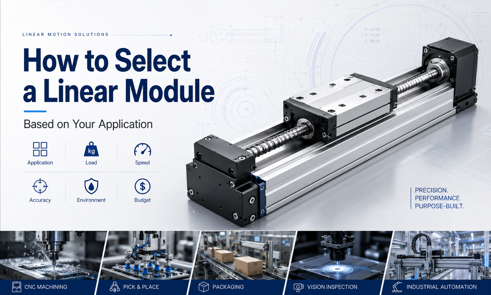
What Is a Linear Module?
A linear module is an integrated linear motion assembly that normally combines a structural base, guide system, moving carriage, drive mechanism, motor interface, support bearings, and optional sensors or protective components.
The module converts motor rotation or electromagnetic force into controlled linear movement. Depending on the drive structure, it may use a ball screw, timing belt, rack and pinion, linear motor, or lead screw.
The moving carriage supports the payload and travels along one or more linear guides. The guide system controls the direction of movement and resists radial loads and moments, while the drive mechanism provides thrust and determines many of the module’s speed, stroke, accuracy, and maintenance characteristics.
Why Application-Based Selection Is Important
Two machines may use linear modules of similar size while requiring completely different internal structures.
A precision inspection system may require low-speed stability, high repeatability, minimal backlash, and a rigid ball screw drive. A packaging machine may require high acceleration, long travel, and rapid point-to-point movement, making a belt driven module more suitable.
A long-stroke heavy-load gantry may require rack and pinion drive, while a semiconductor positioning system may require a linear motor module with encoder feedback and cleanroom-compatible components.
Therefore, linear module selection should begin with the application rather than with a specific product model.
Linear Module Selection Workflow
- Define the application and motion task
- Confirm effective stroke and installation space
- Calculate the total moving load
- Calculate thrust and motor requirements
- Confirm speed, acceleration, and cycle time
- Define accuracy and repeatability requirements
- Calculate pitch, yaw, and roll moments
- Confirm mounting orientation
- Evaluate environmental and protection requirements
- Select the appropriate drive method
- Verify duty cycle and expected service life
- Confirm motor, controller, sensors, and safety devices
- Compare total cost and maintenance requirements
- Perform final technical verification
Step 1: Analyze the Application
The first selection step is to define what the linear module must accomplish. The application determines which performance characteristics are most important.
Questions to Ask During Application Analysis
- What object or tooling will the module move?
- Is the motion primarily transport, positioning, processing, lifting, pressing, or scanning?
- Does the carriage stop at a few positions or follow a continuous path?
- Is the axis installed horizontally, vertically, sideways, inverted, or at an angle?
- Does the load create external cutting, pressing, friction, or insertion forces?
- How often does the axis move?
- How long must the equipment operate each day?
- Will the axis be used independently or as part of a multi-axis system?
- Does the environment contain dust, oil, moisture, chips, chemicals, or cleanroom restrictions?
- What failure risks are unacceptable?
Transport Applications
Transport applications move products, fixtures, pallets, or tools between positions. Typical examples include packaging, sorting, loading, unloading, material transfer, and logistics automation.
These applications often prioritize high speed, acceleration, long stroke, and short cycle time. Belt driven or rack driven modules are frequently suitable.
Precision Positioning Applications
Precision positioning applications include inspection, measurement, optical alignment, electronic assembly, semiconductor processing, and precision dispensing.
These applications usually require high repeatability, low backlash, stable low-speed movement, and high structural rigidity. Ball screw or linear motor modules are generally preferred.
Process Applications
Process applications perform cutting, drilling, dispensing, welding, laser processing, testing, pressing, or controlled insertion while the carriage is moving or stationary.
The module must resist external forces and maintain positioning stability. Drive rigidity, guide capacity, profile stiffness, and process-force direction are especially important.
Vertical Lifting Applications
Vertical axes must overcome gravity and safely hold the load during stopping or power loss. The selection must include motor brake capacity, counterbalance, safety factor, and fall-prevention measures.
Ball screw modules are commonly used when high rigidity and controlled positioning are required. Belt driven modules may be used for high-speed long-stroke lifting when suitable brakes and safety systems are included.
Step 2: Confirm Effective Stroke
Effective stroke is the actual working travel required by the application. It should not be confused with the total length of the linear module.
The required stroke should include the distance between working positions, product dimensions, fixture clearance, acceleration and deceleration space, sensor positions, mechanical end limits, and maintenance access.
Stroke Calculation Considerations
- Distance between the first and last working position
- Length or width of the workpiece
- Tooling overhang
- Safety clearance
- Home and limit sensor positions
- Acceleration and deceleration zones
- Mechanical reserve at both ends
- Future equipment expansion
Selecting a module with insufficient stroke may prevent the machine from reaching all required positions. Selecting a much longer module increases cost, structure length, moving time, and installation space.
Step 3: Calculate the Total Moving Load
The moving load includes more than the product being transported. All components mounted on the moving carriage must be included.
Total Moving Load May Include
- Workpiece or product
- Fixture or gripper
- Moving platform
- Servo motor mounted on another axis
- Camera, sensor, laser head, or dispensing valve
- Cable carrier and moving cables
- Vacuum components and air tubing
- Safety covers or brackets
- Additional motion axes
The total moving mass should include a reasonable engineering margin, but excessive safety factors can lead to unnecessarily large and expensive systems.
Static Load vs Dynamic Load
Static load refers to the weight supported when the carriage is stationary. Dynamic load includes the forces generated during acceleration, deceleration, direction reversal, vibration, and impact.
A module that can support the static weight may still be unsuitable if high acceleration creates excessive guide, screw, belt, bearing, or motor load.
Step 4: Calculate Required Thrust
Thrust is the linear force required to accelerate the load, overcome friction, lift the load, and resist external process forces.
For horizontal movement, the required thrust normally includes acceleration force, friction resistance, and external process force.
For vertical movement, gravity must also be included.
Basic Horizontal Thrust Relationship
The required horizontal thrust can be estimated as:
Required thrust = acceleration force + friction resistance + external force
Acceleration force depends on the total moving mass and acceleration:
Acceleration force = moving mass × acceleration
Basic Vertical Thrust Relationship
For upward vertical movement:
Required thrust = gravity force + acceleration force + friction + external force
For downward movement, gravity assists the motion but creates additional braking and holding requirements.
Additional Forces to Consider
- Cutting or machining force
- Pressing or insertion resistance
- Cable carrier drag
- Seal friction
- Vacuum hose resistance
- Inclined-axis gravity component
- Shock and impact loads
- Misalignment resistance
The selected module should provide sufficient continuous and peak thrust without exceeding the motor, transmission, bearing, or structural limits.
Step 5: Define Speed Requirements
Speed requirements should be based on the actual motion cycle rather than the highest possible travel speed.
Confirm the Following Speed Parameters
- Normal operating speed
- Maximum travel speed
- Acceleration time
- Deceleration time
- Travel distance
- Settling time after stopping
- Process speed during machining or inspection
- Number of cycles per minute
A very high maximum speed may provide little benefit if the stroke is too short for the axis to reach that speed. In short-stroke systems, acceleration and deceleration usually have a greater effect on cycle time.
High-Speed Applications
Timing belt and linear motor modules are commonly selected for high-speed applications. Belt driven modules provide a cost-effective solution for long-stroke transfer, while linear motor modules provide high acceleration and rapid response.
Moderate-Speed Precision Applications
Ball screw modules are suitable when controlled movement, rigidity, and precision are more important than maximum speed.
Long-Stroke Applications
For very long strokes, belt drive, rack and pinion, or linear motor solutions may be more practical than a rotating ball screw because of critical speed, vibration, and screw deflection.
Step 6: Define Acceleration and Cycle Time
Acceleration determines how quickly the load reaches operating speed. It strongly affects motor torque, structural vibration, belt tension, screw load, bearing load, and settling time.
High acceleration can shorten cycle time but may also increase overshoot, vibration, component stress, and maintenance requirements.
Motion Cycle Analysis Should Include
- Starting position
- Acceleration phase
- Constant-speed phase
- Deceleration phase
- Settling time
- Process dwell time
- Return movement
- Total cycles per minute
A realistic motion profile is more useful than a single maximum speed value. Engineers should confirm whether the selected module can maintain the required cycle continuously without overheating.
Step 7: Define Accuracy Requirements
Accuracy requirements must be defined carefully because positioning accuracy, repeatability, resolution, backlash, and straightness are different parameters.
Positioning Accuracy
Positioning accuracy describes how closely the carriage reaches the commanded absolute position.
Repeatability
Repeatability describes how consistently the carriage returns to the same position during repeated cycles.
Resolution
Resolution describes the smallest movement that the controller and feedback system can command or detect.
Backlash and Lost Motion
Backlash and lost motion describe the position difference that may occur during direction reversal because of mechanical clearance, elastic deformation, or transmission compliance.
Straightness and Parallelism
Straightness and parallelism describe the geometric quality of the carriage path relative to the module reference surfaces.
Many applications require good repeatability but do not require extremely high absolute positioning accuracy. Defining excessive accuracy requirements can significantly increase module, motor, encoder, installation, calibration, and maintenance costs.
Typical Accuracy Priorities by Application
| Application | Main Accuracy Requirement |
|---|---|
| Packaging Transfer | Reliable repeatability |
| Pick and Place | Repeatability and settling stability |
| Vision Inspection | Positioning accuracy and straightness |
| Precision Dispensing | Path accuracy and low-speed stability |
| CNC Feeding | Rigidity, positioning accuracy, and backlash control |
| Semiconductor Equipment | High accuracy, repeatability, and clean motion |
| Sorting Equipment | Speed and reliable position repeatability |
Step 8: Calculate Moment Loads
A payload mounted away from the carriage center creates moment loads. These moments may be more critical than the total payload weight.
The three main moment directions are pitch, yaw, and roll.
Moment Load Depends On
- Payload weight
- Distance from the load center of gravity to the carriage
- Tooling overhang
- Carriage width and length
- Guide rail spacing
- Number of guide blocks
- Acceleration direction
- External process forces
A light load installed far from the carriage can create a large moment. This may cause uneven guide loading, reduced accuracy, increased friction, vibration, or premature wear.
Ways to Improve Moment Capacity
- Select a larger module
- Use a longer carriage
- Reduce tooling overhang
- Move the load center closer to the carriage
- Use two parallel modules
- Add external guide rails
- Increase spacing between support points
Step 9: Confirm Mounting Orientation
Mounting orientation changes the forces acting on the module and can significantly affect load capacity and motor requirements.
Horizontal Installation
In horizontal applications, the module mainly overcomes inertia, friction, and external process force. The guide system supports the payload weight.
Vertical Installation
In vertical applications, the drive system must continuously overcome gravity during upward movement and safely control the load during downward movement.
A brake motor, counterbalance, mechanical lock, or fall-prevention device may be necessary.
Side-Mounted Installation
Side mounting changes the load direction acting on the guide blocks and may reduce allowable payload or moment capacity.
Inverted Installation
Inverted installation places the payload below the carriage. Fasteners, safety factors, guide preload, lubrication, and contamination protection require careful evaluation.
Inclined Installation
An inclined axis contains both horizontal and vertical force components. The gravity component along the motion direction must be included in thrust calculations.
Step 10: Select the Drive Method
The drive method determines many of the module’s performance characteristics.
Ball Screw Linear Module
Ball screw modules are suitable for applications requiring high positioning accuracy, strong axial rigidity, good repeatability, controlled low-speed motion, and moderate stroke.
Typical Advantages
- High positioning accuracy
- Good repeatability
- Strong axial rigidity
- High transmission efficiency
- Suitable for precision servo control
- Good thrust capability
Typical Limitations
- Critical speed limitations on long strokes
- Requires lubrication
- Usually higher cost than belt drive
- Can generate noise at high rotational speed
Timing Belt Linear Module
Timing belt modules are suitable for long-stroke, high-speed transport and rapid point-to-point movement.
Typical Advantages
- High travel speed
- High acceleration
- Suitable for long strokes
- Lower moving inertia
- Relatively simple structure
- Competitive cost
Typical Limitations
- Lower axial rigidity
- Belt elasticity affects positioning
- Requires belt tension inspection
- Less suitable for high-force pressing
Rack and Pinion Linear Module
Rack and pinion modulesare suitable for long travel, heavy loads, large gantry systems, and industrial transport axes.
Typical Advantages
- Suitable for very long strokes
- High load and thrust capability
- No long rotating screw limitation
- Suitable for large gantry systems
Typical Limitations
- Backlash control requires careful design
- Gear lubrication may be required
- Noise may be higher
- Precision depends on rack quality and preload
Linear Motor Module
Linear motor modules are suitable for high-speed, high-acceleration, high-precision, and highly dynamic applications.
Typical Advantages
- No mechanical transmission backlash
- Very high acceleration
- High speed
- Direct-drive response
- Suitable for precision feedback control
Typical Limitations
- Higher initial cost
- Requires linear encoder feedback
- Requires thermal management
- May require magnetic-force safety considerations
Step 11: Evaluate the Operating Environment
The environment can determine whether an open, semi-enclosed, or fully enclosed module is required.
Dust and Particles
Dust, metal chips, wood particles, abrasive powder, and packaging debris can enter guide blocks, ball nuts, belts, pulleys, and bearings.
Protective covers, sealing strips, bellows, positive-pressure air, or fully enclosed structures may be required.
Oil and Coolant
Oil mist and coolant can affect belts, seals, lubrication, sensors, and motor connections. Material compatibility should be verified.
Moisture and Washdown
Wet environments require corrosion-resistant materials, sealed motors, protected sensors, and suitable drainage. Standard open modules are normally unsuitable for direct washdown.
Cleanroom Applications
Cleanroom modules may require low-particle lubrication, sealed guide systems, stainless-steel components, vacuum extraction, special cables, and low-emission materials.
Vacuum Applications
Vacuum-compatible modules require special lubricants, materials with low outgassing, suitable motor and sensor components, and careful thermal design.
High and Low Temperature
Temperature affects lubricant viscosity, belt tension, screw expansion, bearing clearance, seals, motor performance, and positioning accuracy.
Corrosive or Chemical Environments
Chemical exposure may require stainless steel, special coatings, resistant belts, compatible seals, and protective enclosures.
Step 12: Confirm Protection Level
Protection level should be selected according to actual exposure rather than appearance.
A module with a cover plate may still allow dust or moisture to enter through the moving carriage opening. The complete assembly, including motor, sensors, cables, connectors, and moving seals, must be evaluated.
Possible Protection Options
- Open structure
- Top cover plate
- Steel sealing strip
- Fully enclosed profile
- Protective bellows
- Positive-pressure air purge
- Corrosion-resistant components
- External safety enclosure
Step 13: Evaluate Duty Cycle
Duty cycle describes how often and how long the module operates.
Duty Cycle Information Should Include
- Operating hours per day
- Cycles per minute
- Distance per cycle
- Acceleration and deceleration frequency
- Time at maximum speed
- Process dwell time
- Continuous or intermittent operation
- Expected annual travel distance
A module operating occasionally at high load may require a different design from one operating continuously at moderate load.
Motor RMS torque, screw temperature, belt fatigue, bearing life, guide life, lubrication interval, and controller capacity should be checked using the complete duty cycle.
Step 14: Estimate Service Life
Expected service life should be defined in travel distance, operating hours, or total cycles.
Guide and ball screw life can be estimated from dynamic load ratings, but actual life depends on installation, lubrication, contamination, shock, vibration, temperature, and maintenance.
Factors That Reduce Service Life
- Excessive payload
- High moment load
- Insufficient lubrication
- Contamination
- Incorrect alignment
- Shock loading
- Excessive acceleration
- Improper belt tension
- Operation beyond rated speed
- High temperature
Step 15: Select the Motor and Drive
The motor must provide sufficient peak and continuous torque for the complete motion cycle.
Motor Selection Should Consider
- Required thrust
- Maximum speed
- Acceleration
- Load inertia
- Transmission ratio
- Screw lead or pulley diameter
- Vertical gravity load
- Duty cycle
- Brake requirement
- Positioning performance
Servo Motor
Servo motors provide closed-loop control, high dynamic response, accurate positioning, torque monitoring, and flexible motion profiles.
Stepper Motor
Stepper motors may provide a lower-cost solution for moderate-speed and moderate-accuracy applications. However, open-loop systems can lose position if overloaded.
Brake Motor
A motor brake is commonly required for vertical axes or systems that must hold position during power loss.
Step 16: Confirm Sensor Requirements
Linear modules may require home sensors, positive and negative limit sensors, intermediate position sensors, or external linear encoders.
Common Sensor Functions
- Home position detection
- End-of-travel protection
- Overtravel prevention
- Position confirmation
- Product presence detection
- External closed-loop feedback
- Safety monitoring
Sensor mounting locations should be confirmed before ordering because some module structures have limited space for later installation.
Step 17: Consider Cable Management
Moving cables, air tubes, vacuum hoses, and sensor wires can create significant drag and affect motion accuracy.
A cable carrier should be selected according to bending radius, travel length, acceleration, cable quantity, and installation space.
Cable Management Considerations
- Cable bending radius
- Cable carrier self-weight
- Moving drag force
- High-flex cable life
- Tube pressure and vacuum requirements
- Interference with adjacent structures
- Cleanroom or low-particle requirements
Step 18: Evaluate Safety Requirements
Safety requirements are especially important for vertical axes, heavy loads, high-speed systems, and machines accessible to operators.
Possible Safety Measures
- Motor brake
- Mechanical end stops
- Positive and negative limit sensors
- Emergency stop system
- Protective enclosure
- Fall-prevention device
- Safety nut or mechanical lock
- Torque and overload monitoring
- Safe-speed control
- Collision detection
Mechanical safety should not rely only on software limits.
Step 19: Evaluate Budget and Total Cost
The lowest-priced module is not always the lowest-cost solution. Total cost includes design, motor, controller, brackets, installation, commissioning, maintenance, spare parts, energy use, downtime, and product quality.
Total Cost May Include
- Linear module purchase price
- Servo or stepper motor
- Drive and controller
- Mounting brackets and frame
- Sensors and cables
- Cable carrier
- Protective cover
- Installation labor
- Programming and commissioning
- Lubrication and maintenance
- Replacement belts, screws, bearings, or seals
- Production downtime
- Product defects caused by insufficient accuracy
A high-precision module may be unnecessary for simple transport. A low-cost module may be expensive in the long term if it causes unstable positioning or frequent maintenance.
Application-Based Linear Module Selection
CNC Machine Tool Selection
CNC applications require high rigidity, low backlash, strong thrust, and stable feed motion. Ball screw modules or custom ball screw stages are generally preferred.
Important parameters include cutting force, axis rigidity, thermal stability, positioning accuracy, guide preload, and lubrication.
Pick-and-Place Selection
Pick-and-place applications require short cycle time, rapid acceleration, reliable repeatability, and low moving mass.
Belt driven modules are suitable for long-stroke high-speed transfer. Ball screw modules are suitable when higher precision or greater rigidity is required.
Packaging Machine Selection
Packaging equipment often prioritizes speed, long stroke, simple maintenance, and competitive cost. Belt driven modules are commonly selected.
Precision Dispensing Selection
Dispensing applications require path accuracy, smooth low-speed movement, stable velocity, and minimal vibration. Ball screw or linear motor modules are usually suitable.
Vision Inspection Selection
Vision inspection systems require stable positioning, low vibration, straight travel, and repeatable camera alignment. Ball screw and linear motor modules are common choices.
Semiconductor Equipment Selection
Semiconductor equipment may require high precision, cleanroom compatibility, low particle generation, compact structure, and encoder feedback.
Ball screw, linear motor, and cleanroom-specific modules may be used depending on speed and accuracy requirements.
Battery Manufacturing Selection
Battery production equipment often requires high speed, long operating hours, dust control, and resistance to process contamination.
Selection should consider sealing, cable management, lubrication, cycle rate, and maintenance access.
Long-Stroke Gantry Selection
Long-stroke gantry systems require careful control of straightness, synchronization, load distribution, and structural rigidity.
Belt driven or rack driven modules are commonly selected. Dual-drive systems may require electronic gantry synchronization.
Vertical Loading and Unloading Selection
Vertical loading systems require sufficient thrust, brake capacity, safety devices, and controlled deceleration.
Ball screw modules are often selected for precision and rigidity, while belt modules can be used for high-speed long-stroke lifting with appropriate protection.
Common Linear Module Selection Mistakes
Selecting Only by Payload
Payload does not include moment, acceleration, external force, or duty-cycle effects.
Ignoring the Center of Gravity
A load within the weight limit may still exceed allowable moment capacity when mounted far from the carriage.
Using Maximum Catalog Values Together
Maximum speed, maximum payload, maximum stroke, and maximum acceleration usually cannot be achieved simultaneously.
Confusing Accuracy with Repeatability
A system can return to the same position consistently while still having absolute position error.
Ignoring Installation Surface Quality
A poor mounting surface can distort the module and reduce accuracy and service life.
Ignoring Cable Drag
Cable carriers and hoses can add significant moving resistance and moment load.
Ignoring Environmental Protection
An open module may fail prematurely in dusty, wet, or abrasive environments.
Assuming Ball Screws Are Self-Locking
Vertical ball screw axes may back-drive and require a brake or fall-prevention device.
Over-Specifying Accuracy
Unnecessary precision increases product and integration cost.
Comparing Only Purchase Price
The complete system and lifetime cost should be considered.
Linear Module Selection Checklist
- Application type confirmed
- Effective stroke confirmed
- Total moving load calculated
- Thrust calculated
- Speed and acceleration confirmed
- Cycle time evaluated
- Accuracy and repeatability defined
- Moment loads calculated
- Mounting orientation confirmed
- Drive type selected
- Environment evaluated
- Protection structure selected
- Duty cycle confirmed
- Service life estimated
- Motor and brake selected
- Sensors confirmed
- Cable carrier selected
- Safety measures confirmed
- Installation space verified
- Total cost evaluated
Frequently Asked Questions
What is the first step when selecting a linear module?
The first step is to define the application and motion cycle, including what must move, how far it must travel, how fast it must move, and what accuracy or force is required.
Which linear module is best for high accuracy?
Ball screw and linear motor modules are commonly selected for high-accuracy applications. The final choice depends on stroke, speed, load, environment, and budget.
Which linear module is best for high speed?
Timing belt and linear motor modules generally provide the highest speed and acceleration.
Which module is suitable for long stroke?
Timing belt, rack and pinion, and linear motor modules are generally more suitable for long strokes than conventional ball screw modules.
How should I select a linear module for vertical installation?
Calculate gravity load, acceleration force, brake capacity, holding requirements, and fall-prevention measures. Do not assume that the screw will self-lock.
How much safety factor should be used?
The safety factor depends on load uncertainty, shock, duty cycle, environment, and failure consequences. It should be reasonable and application-specific rather than excessively large.
Can I select a module using only the maximum payload value?
No. Speed, acceleration, moment load, stroke, mounting direction, thrust, and service life must also be considered.
Which drive type is most cost-effective?
Timing belt modules are often cost-effective for high-speed long-stroke transport. Ball screw modules provide better value when accuracy and rigidity are critical.
Do all linear modules need lubrication?
Most guide systems require lubrication. Ball screw modules also require screw lubrication, while belts normally do not require lubrication.
When should an external linear encoder be used?
An external encoder may be useful when high absolute accuracy is required, mechanical transmission error must be compensated, or direct carriage-position feedback is necessary.
Conclusion
Learninghow to choose a linear modulerequires more than comparing product catalog specifications. The correct solution must be selected according to the complete application.
Begin by defining the motion task, stroke, moving load, thrust, speed, acceleration, cycle time, accuracy, moment load, installation direction, environment, duty cycle, service life, safety requirements, and budget.
Choose aball screw modulewhen accuracy, rigidity, low-speed stability, and thrust are the main priorities. Choose atiming belt modulewhen high speed, long stroke, rapid acceleration, and lower initial cost are more important. Choose a rack driven module for long-stroke heavy-load systems, and choose a linear motor module for high-dynamic, high-speed, and high-precision applications.
The best linear module is not the model with the highest specification. It is the module that reliably satisfies the required performance without unnecessary cost, complexity, size, or maintenance.
By following a structured application-based selection workflow, engineers can reduce design risk, avoid oversizing, improve equipment stability, and build a more efficient and economical linear motion system.
