 English

Alinear modulethrust calculation answers a practical design question: how much axial force must the drive produce at every part of the motion cycle? The answer is not simply the payload weight. Acceleration, gravity, process force, guide and seal resistance, cable drag, transmission efficiency, and the selected motion profile can all change the required force.
Undersizing causes slow acceleration, following error, overheating, stalling, or an inability to hold a vertical axis. Oversizing the motor without checking the module is also unsafe because the ball screw, belt, rack, bearings, carriage, and structure still have their own axial-load, moment, speed, and life limits.
This guide develops the calculation from force to motor torque, distinguishes horizontal and vertical axes, explains the conversion for common drive mechanisms, and completes a fully worked teaching example. All numerical examples are hypothetical and illustrate the method only; they are not specifications for a QRXQ product or data from a customer project.
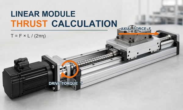
What thrust must a linear module produce?
Required thrust is the signed force along the module's direction of travel. It must overcome the inertia of the moving mass and all forces projected onto that axis. The calculation must be repeated for acceleration, constant-speed travel, deceleration, dwell or holding, and both travel directions.
General signed force balance:F_axis = m × a + F_process + F_friction + F_gravity
Choose one positive travel direction and keep it throughout the calculation. In this guide, F_process and F_friction are entered as the signed motor-force contributions required to overcome those loads: a resistance that the motor must overcome during positive travel is positive, while the corresponding contribution during negative travel is negative. F_gravity is the motor-force contribution required to balance gravity in the chosen coordinate system. This convention matters during deceleration and downward travel because the motor may be braking or regenerating rather than driving in the original direction.
Thrust is not the same as payload capacity. The guide supports radial loads and moment loads, while the transmission supplies axial drive force. A module can have enough thrust yet still be unsuitable because the carriage moment, guide life, screw buckling load, belt tooth load, bearing load, or structural deflection is excessive.
Collect the inputs before calculating force
Use the actual moving mass, motion profile, installation direction, and external forces. If cable drag, seal resistance, or process force can be measured, use the measured value at the relevant speed and direction. A generic friction coefficient is only a preliminary estimate and may not represent preload, seals, lubrication, cable carriers, or assembly misalignment.
| Symbol | Meaning | Typical unit | How to obtain it |
|---|---|---|---|
| m | Total moving mass, including carriage-mounted tooling and workpiece | kg | Mass model or measured mass |
| a | Signed linear acceleration for each motion segment | m/s² | Motion profile |
| v | Maximum linear speed | m/s or mm/s | Cycle requirement |
| g | Gravitational acceleration | 9.81 m/s² | Physical constant |
| i | Axis angle above horizontal | degrees | Machine layout |
| F_process | Machining, pressing, dispensing, tensioning, or other external force along the axis | N | Process data or measurement |
| F_friction | Guide, seal, bearing, cable-carrier, and other running resistance | N | Measurement or confirmed component data |
| L | Ball screw lead: linear travel per revolution | m/rev or mm/rev | Screw specification |
| r | Effective pulley or pinion pitch radius | m | Drive geometry |
| or | Mechanical efficiency of the relevant transmission path | dimensionless | Manufacturer data at the operating condition |
| i | Reduction ratio defined as motor speed divided by driven-shaft speed | dimensionless | Gearbox or pulley ratio |
| J_rot,m | Total rotating inertia expressed at the motor shaft, excluding linear mass already included in m × a | kg·m² | Component inertia calculation |
Build the axial-force equation for each operating condition
Horizontal axis
For a level axis, gravity has no component along the travel direction. A preliminary force balance is:
Horizontal axis:F_axis = m × a + F_process + F_friction
Physical friction always opposes motion. Under the required-drive-force convention used here, the friction contribution is positive during rightward travel when right is positive, and negative during leftward travel. A strict free-body diagram uses the opposite physical-force sign and then solves for motor force; both methods give the same answer if used consistently. In a sizing worksheet, write one row for each segment and enter every contribution with its sign.
Inclined and vertical axes
For an axis inclined by θ above horizontal, the gravity component along the slope has magnitude m × g × sin θ. If the positive direction is uphill:
Inclined axis:F_axis = m × a + m × g × sin θ + F_process + F_friction
For a vertical axis moving upward, θ = 90 degrees and the gravity term becomes m × g. The upward-acceleration case is commonly the largest positive drive-force demand:
Vertical upward acceleration:F_up = m × (g + a) + F_process + F_friction
Downward motion must still be calculated as a signed segment. Gravity may drive the load, so the motor and drive may need to absorb regenerative energy. A holding brake is a safety and holding device; it is not a substitute for calculating the motor torque required during controlled motion.
Process force and resistance
Only include forces that act during the relevant segment. A pressing force may be present during a working stroke but absent during positioning and return. Cable drag may vary with carriage position. Breakaway resistance can exceed running resistance. These differences are why one worst-case force estimate cannot replace a segment-by-segment calculation.
Convert required thrust into motor torque
Ball screw drive
For a ball screw with lead L in metres per revolution and forward efficiency η_s, the torque required at the screw to produce axial force is:
Screw torque from thrust:T_screw = F_axis × L ÷ (2 × π × η_s)
If a gearbox is installed and i is motor speed divided by screw speed:
Motor load torque:T_load,m = T_screw ÷ (i × η_g)
Motor speed:n_motor = 60 × v × i ÷ L
Use one unit system throughout. If F is in newtons and L is in metres per revolution, torque is in newton-metres. If L is entered in millimetres per revolution, convert it to metres before calculating torque in newton-metres.
Timing-belt and rack-and-pinion drives
For a belt pulley or rack pinion, use the effective pitch radius rather than an outside diameter:
Driven-shaft torque:T_driven = F_axis × r ÷ η_d
Motor load torque:T_load,m = F_axis × r ÷ (η_d × i × η_g)
Motor speed:n_motor = 60 × v × i ÷ (2 × π × r)
The same force-to-radius relationship applies, but the catalog checks differ. A timing-belt module requires verification of allowable belt tension, tooth engagement, pulley load, belt life, and positioning behavior. A rack-and-pinion system requires verification of tooth force, pinion and rack rating, gearbox load, backlash, lubrication, and structural stiffness.
Linear motor drive
A direct-drive linear motor does not need a rotary torque conversion. Its motor force is compared directly with the calculated axis force. Check peak force, continuous force over the duty cycle, thermal conditions, available bus voltage at speed, encoder performance, and the ability of the guide and structure to carry the payload and moments.
Add rotational acceleration torque without double counting
The force-domain method in this guide already includes the linear inertia term m × a. After converting that force to motor torque, add only the torque needed to accelerate rotating components that were not already represented in the force calculation:
Motor angular acceleration:α_m = 2 × π × a × i ÷ L for a ball screw
Rotational acceleration torque:T_rot = J_rot,m × α_m
Total motor torque by segment:T_motor = T_load,m + T_rot + T_other
T_other can include confirmed preload, bearing, seal, brake-release, or gearbox losses not captured by the transmission efficiency. Do not include m × a in the force balance and then include the same moving mass again as reflected inertia in J_rot,m; that would count the linear acceleration load twice. An alternative torque-domain method may use reflected linear inertia, but then its corresponding m × a force term must be removed.
Worked example: horizontal ball-screw linear module
Teaching-data statement:The following values are hypothetical and are used only to demonstrate a linear module force calculation. They do not represent a QRXQ model, catalog rating, test result, or customer application.
Input conditions
| Input | Assumed value | Notes |
|---|---|---|
| Total moving mass m | 80 kg | Carriage, fixture, and workpiece |
| Maximum acceleration magnitude a | 2.0 m/s² | 0.20 s to reach 0.40 m/s |
| Maximum speed v | 0.40 m/s | 400 mm/s |
| Measured running resistance | 35 N | Guide, seals, and cable carrier combined |
| Process force | 120 N | Present only during forward constant-speed work |
| Ball screw lead L | 20 mm/rev | 0.020 m/rev |
| Assumed screw efficiency η_s | 0.90 | Must be replaced by confirmed product data |
| Drive ratio i | 1.0 | Direct coupling |
| Rotating inertia at motor shaft J_rot,m | 0.00015 kg·m² | Hypothetical combined motor, coupling, and screw value |
| Illustrative design margin | 1.25 | Project assumption, not a universal manufacturer rule |
Step 1: calculate force for each motion segment
During forward acceleration, the process has not started:
F_accel = 80 × 2.0 + 35 =195 N
During forward constant-speed processing:
F_process-run = 0 + 35 + 120 =155 N
During forward deceleration after the process force is removed:
F_decel = -80 × 2.0 + 35 =-125 N
The negative sign means the required motor force reverses direction under the selected sign convention. On the return stroke, the acceleration and friction signs reverse. The maximum absolute axis force in this simplified cycle is 195 N.
Step 2: convert force into screw torque
The force-to-torque factor is:
L ÷ (2 × π × η_s) = 0.020 ÷ (2 × π × 0.90) =0.0035368 N·m per N
Forward-acceleration torque caused by linear force is:
T_force,accel = 195 × 0.0035368 =0.690 N·m
Constant-speed process torque is:
T_process-run = 155 × 0.0035368 =0.548 N·m
Step 3: add rotating-component acceleration torque
Motor angular acceleration is:
α_m = 2 × π × 2.0 ÷ 0.020 =628.32 rad/s²
Rotational acceleration torque is:
T_rot = 0.00015 × 628.32 =0.094 N·m
Therefore, the forward-acceleration motor torque is:
T_motor,accel = 0.690 + 0.094 =0.784 N·m
Step 4: calculate required motor speed
n_motor = 60 × 0.40 ÷ 0.020 =1,200 r/min
The selected servo must supply the required torque at this speed. A standstill peak-torque value alone does not prove that the motor can meet the operating point.
Step 5: calculate RMS torque over the cycle
Assume a 3.4 s cycle with 0.2 s forward acceleration, 1.0 s forward processing, 0.2 s forward deceleration, 0.3 s dwell, 0.2 s return acceleration, 1.0 s constant-speed return, 0.2 s return deceleration, and 0.3 s dwell. The corresponding hypothetical motor torques are 0.784, 0.548, -0.536, 0, -0.784, -0.124, 0.536, and 0 N·m.
RMS formula:T_rms = square root of [Σ(T_k² × t_k) ÷ Σt_k]
T_rms = square root of [(0.784² × 0.2 + 0.548² × 1.0 + 0.536² × 0.2 + 0² × 0.3 + 0.784² × 0.2 + 0.124² × 1.0 + 0.536² × 0.2 + 0² × 0.3) ÷ 3.4]
T_rms =0.446 N·m
Step 6: turn the result into a preliminary servo requirement
Applying the illustrative 1.25 modeling margin gives:
- Initial axial-force target: 195 × 1.25 =244 N
- Peak motor-torque target: 0.784 × 1.25 =0.980 N·m
- RMS motor-torque target: 0.446 × 1.25 =0.558 N·m
- Required motor speed:1,200 r/min
A preliminary servo candidate should have a rated torque above the margin-adjusted RMS requirement and a permissible peak torque above the margin-adjusted peak requirement at the relevant speed. Final selection must also pass the motor speed-torque curve, drive-current limit, inertia-ratio guidance for that servo family, regenerative-energy check, thermal derating, and module mechanical limits.
Short vertical-axis check
Consider a separate hypothetical vertical axis with a 40 kg moving mass, upward acceleration of 1.5 m/s², 25 N of measured resistance, a 10 mm/rev ball screw, and assumed efficiency of 0.90. With no process force:
F_up = 40 × (9.81 + 1.5) + 25 =477.4 N
T_screw = 477.4 × 0.010 ÷ (2 × π × 0.90) =0.844 N·m
With the illustrative 1.25 margin, the preliminary values become 596.8 N and 1.055 N·m before adding rotating-component acceleration torque. The axis still needs a downward-motion and deceleration analysis, a regenerative-energy check, and a brake and safety assessment. This example shows why a horizontal-axis result cannot be reused for a vertical installation.
Apply a safety margin to uncertainty, not to every term repeatedly
A margin should cover defined uncertainty such as friction variation, cable-carrier force, payload tolerance, efficiency variation, wear, shock, or a not-yet-finalized process load. Do not multiply the mass, acceleration, force, torque, and motor rating by separate arbitrary factors; stacked factors can conceal a poor model and produce unnecessary oversizing.
Document what the margin covers and compare it with the manufacturer's sizing method. High shock, uncertain process forces, vertical personnel hazards, or severe duty may require a different design approach rather than a larger generic multiplier. Whenever possible, measure breakaway and running force on the assembled mechanism and update the calculation.
Catalog checks required after the thrust calculation
The calculated drive force and motor torque are inputs to selection, not the final selection. Check all of the following against the exact module, transmission, motor, and drive documentation:
- Peak axial load:screw, nut, belt, rack, pinion, bearing, coupling, and carriage limits.
- Static safety and buckling:especially a long ball screw under compressive load.
- Dynamic life:use the manufacturer's load-rating definitions, load spectrum, lubrication assumptions, and correction factors.
- Permissible speed:screw critical speed, ball circulation limit, belt speed, bearing speed, and motor maximum speed.
- Guide load and moments:radial load plus roll, pitch, and yaw moments from payload offset and process force.
- Rigidity and accuracy:screw stretch, structural deflection, belt compliance, backlash, thermal growth, and settling requirement.
- Servo duty:peak torque, RMS torque, torque-speed curve, inertia ratio, drive current, regeneration, brake, ambient temperature, and enclosure cooling.
- Vertical-axis safety:brake behavior, uncontrolled descent risk, counterbalance if used, safe stopping, and applicable machine-safety requirements.
Common linear module force calculation errors
- Using payload weight as horizontal thrust even though gravity is perpendicular to travel.
- Ignoring tooling, carriage-mounted equipment, or a changing workpiece mass.
- Applying the horizontal formula to a vertical or inclined axis.
- Using constant-speed force as the peak requirement and omitting acceleration.
- Using nominal motor torque without checking peak torque, RMS torque, speed, or duty cycle.
- Mixing millimetres and metres in the screw-lead or pulley-radius equation.
- Using pulley outside diameter instead of effective pitch radius.
- Assuming a universal transmission efficiency instead of confirmed operating data.
- Counting m × a in the force equation and counting the same linear mass again in reflected inertia.
- Applying a margin to every intermediate result and unintentionally compounding it.
- Checking motor capability but not screw buckling, belt rating, guide moments, bearing load, or life.
- Ignoring regenerative energy and holding requirements on a vertical axis.
Information to prepare for final servo and module selection
- Axis orientation, travel direction, stroke, and mounting arrangement.
- Complete moving-mass breakdown and payload range.
- Payload centre of gravity and offsets from the guide carriage.
- Maximum speed, acceleration, deceleration, move distance, move time, dwell, and cycles per minute.
- Process-force magnitude, direction, location, and duration.
- Measured or confirmed breakaway and running resistance, including cable carriers and seals.
- Selected screw lead, pulley pitch diameter, rack pinion radius, gearbox ratio, and efficiencies.
- Rotating inertia of the screw, pulleys, coupling, gearbox, brake, and motor rotor.
- Required positioning accuracy, repeatability, settling time, rigidity, and service-life target.
- Ambient temperature, contamination, lubrication, washdown, cleanroom, or vacuum requirements.
- Power supply, servo-drive limits, braking or regeneration arrangement, and safety requirements.
Selection conclusion
A reliable linear module thrust calculation follows a closed loop: define the motion segments, calculate signed force for each segment, convert force through the actual drive geometry and efficiency, add only the remaining rotating-inertia torque, and calculate both peak and RMS motor torque. Then compare the results with the motor torque-speed envelope and every relevant mechanical catalog limit.
For the hypothetical horizontal ball-screw example, the preliminary margin-adjusted requirements are 244 N axial force, 0.980 N·m peak motor torque, 0.558 N·m RMS torque, and 1,200 r/min. These values are not a product recommendation. A final model can only be chosen after its screw or belt capacity, guide moments, speed, life, rigidity, motor-drive limits, thermal conditions, and safety functions have all been verified.
