 English

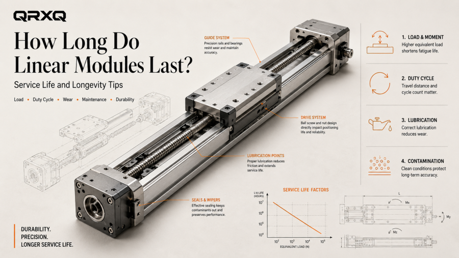
There is no single answer to the question “How long does alinear modulelast?” A correctly sized module in a clean, moderate-duty machine can remain stable for years, while the same basic module can wear much faster if it is overloaded, misaligned, contaminated or operated continuously near its mechanical limits.
Linear module service lifeis therefore better understood as the result of a complete operating condition rather than a fixed number of hours or cycles. The guide bearings, ball screw, belt, rack, support bearings, seals and lubrication system can all have different life-limiting mechanisms.
This guide explains how engineers should evaluate linear module lifetime, which factors have the greatest effect on wear, how calculated life differs from real service life, and what can be done to extend the durability of a precision linear motion system.
Service Life Is Not the Same as a Warranty Period
A warranty is a commercial commitment made by a manufacturer. Service life is an engineering outcome that depends on how the axis is selected, installed and operated.
A linear module may still be mechanically usable after its calculated bearing life has been reached, or it may require maintenance much earlier because of contamination, lubrication failure, belt damage or an installation problem. This is why a useful lifetime estimate must start from the actual application.
Key point:linear module life should be evaluated from load, speed, acceleration, stroke, duty cycle, mounting orientation, environment and maintenance—not from calendar age alone.
What Usually Limits the Life of a Linear Module?
A complete module contains several wear-sensitive components. The first component to reach its allowable wear, fatigue or maintenance limit can determine the service interval of the entire axis.
| Component | Typical Life-Limiting Mechanism | Important Influences |
|---|---|---|
| Linear guide | Rolling-contact fatigue, wear, contamination damage | Equivalent load, moment load, lubrication, alignment |
| Ball screw | Rolling fatigue, raceway wear, preload loss | Axial load, speed, lubrication, shock, support accuracy |
| Timing belt | Tooth wear, tensile-member fatigue, cracking, tension loss | Acceleration, pulley size, tension, temperature, contamination |
| Rack and pinion | Tooth wear, pitting, backlash growth | Tooth load, lubrication, alignment, debris |
| Support bearings | Fatigue or lubrication-related wear | Axial/radial load, preload, speed, temperature |
| Seals and wipers | Abrasion, hardening, tearing | Dust, chemicals, temperature, travel speed |
| Couplings and fasteners | Fatigue, loosening, fretting | Alignment, vibration, torque cycles, installation quality |
This is why “the module lifetime” is not one isolated catalog value. A ball screw may have a calculated rolling fatigue life, while a timing belt is evaluated through a different set of operating limits and inspection criteria.
Calculated Life: What the Engineering Number Actually Means
For rolling-element components such as linear guides and ball screws, manufacturers commonly provide a dynamic load rating that can be used to estimate a statistical rating life under defined conditions.
In simplified form, rating life is strongly related to the ratio between the component's dynamic load capacity and the equivalent operating load:
Conceptual relationship:rating life ∝ (dynamic load rating ÷ equivalent load)p
For many ball-based rolling systems, the exponentpis commonly 3. Other rolling-element designs can use a different exponent. The exact calculation should always follow the component or module manufacturer's method because correction factors, preload, hardness, temperature and reliability requirements may also apply.
Why load has such a large effect on lifetime
Because the relationship is nonlinear. If the equivalent load increases substantially, calculated rolling-contact life can fall much faster than the load increase might suggest.
This is one reason to avoid selecting a module only from a published “maximum payload.” A module operating continuously near a limit does not have the same fatigue margin as one working at a moderate equivalent load.
What is L10 or basic rating life?
For rolling bearings and many linear rolling components, basic rating life is commonly expressed statistically. It is not a guarantee that every component will fail at a particular distance or cycle count.
In practical engineering, the value is used as a common basis for comparing designs under specified loads. Real machine life can be shorter or longer depending on lubrication, cleanliness, alignment, shock and manufacturing variation.
Payload Is Only One Part of the Load
The load acting on a linear module is not always equal to the mass placed on the carriage.
The guide system may also experience:
- Inertial force during acceleration and deceleration
- Pitch, yaw and roll moments from an offset center of gravity
- Gravity on a vertical axis
- External process forces such as pressing, cutting or clamping
- Shock from hard stops, collisions or rapidly changing loads
- Loads transmitted from another axis in a multi-axis structure
Why an offset load can shorten life
If the payload is positioned far away from the carriage, the resulting moment can load one side of the guide much more heavily than the nominal payload suggests. A light but highly overhung tool can therefore be more demanding than a heavier load mounted close to the carriage center.
For applications with large tooling plates, robots, cameras or grippers, the center-of-gravity position should be included in the life calculation.
Why acceleration changes the picture
During acceleration, the module must generate force to accelerate the moving mass in addition to overcoming friction, gravity and process loads. Frequent rapid reversals can create a high repeated load even when the static payload is modest.
This is especially important in pick-and-place, packaging and electronics equipment where cycle time is short and the axis reverses direction thousands of times per shift.
Duty Cycle: A Module That Moves All Day Is a Different Application
Two machines can use the same stroke, payload and maximum speed but have very different service-life expectations.
Consider the difference between an adjustment axis that moves ten times per hour and a transfer axis that moves every two seconds. Even if their peak loads are identical, the second system accumulates far more rolling distance, belt flex cycles and thermal exposure.
Useful duty-cycle information to record
- Cycles per minute or per hour
- Operating hours per day
- Travel distance per cycle
- Acceleration and deceleration time
- Dwell time
- Percentage of time under high process load
- Expected annual production days
For lifetime estimation, total travel distance or total cycle count is often more meaningful than saying the machine has been in service for “three years.”
Speed Does Not Always Wear a Module in the Same Way
Higher speed can increase heat generation, lubricant shear, belt flex frequency and the sensitivity of long screws to dynamic limitations. But speed alone is not a universal wear indicator.
An axis moving at high speed under light load for short periods can have a very different wear pattern from an axis moving slowly under heavy load around the clock.
Ball screw systems
Ball screw modulesmust remain within the screw's allowable rotational speed and dynamic limits. Long screws are increasingly sensitive to critical speed, vibration and support stiffness. High speed also increases the importance of lubrication and thermal stability.
Timing belt systems
Belt life is influenced by bending around pulleys, tooth loading, belt tension and acceleration. Smaller pulleys increase belt bending, while excessive tension increases bearing and belt loads. Incorrect alignment can cause edge wear and tracking problems.
Rack-and-pinion systems
At higher speed, gear alignment, lubrication and tooth contact quality become increasingly important. Contamination on an open rack can accelerate wear at the contact surfaces.
The Main Wear Mechanisms to Watch
Rolling-contact fatigue
Linear guide raceways and ball screw grooves carry repeated contact stress. Over long operating periods, fatigue can eventually produce surface damage such as flaking or pitting.
Correct load distribution, adequate lubrication and keeping contamination out of the raceway are essential for achieving the intended fatigue life.
Abrasive wear
Dust, metal particles and other hard contamination can enter seals and be rolled repeatedly through the contact zone. This can scratch or indent precision surfaces and accelerate wear much faster than clean operation.
Adhesive or lubrication-related wear
If the lubricant film is inadequate, direct surface interaction increases. Friction, temperature and wear may rise, eventually damaging raceways, screws or gears.
Corrosion
Moisture, process chemicals and condensation can attack unprotected metal surfaces. Corrosion damage can then create rough contact surfaces that accelerate mechanical wear.
Fatigue of flexible transmission elements
Timing belts experience repeated bending and tensile loading. Over time, tooth wear, cracking, cord fatigue or tension loss may appear. Belt replacement can therefore be a normal maintenance event even when the guide system remains in good condition.
Installation Quality Can Add Years—or Remove Them
A precision linear module should be mounted to a sufficiently flat and rigid base. Forcing the module onto a twisted or uneven machine frame can introduce internal stress and uneven guide loading.
Installation problems that commonly reduce service life include:
- Mounting to a surface outside the required flatness
- Misalignment between two parallel modules
- Incorrect motor-to-screw coupling alignment
- Fasteners that loosen under repeated acceleration
- External side load not considered during machine design
- Cable carriers that pull laterally on the carriage
- Insufficient support under a long module base
A module with a high catalog load rating can still fail early if the machine structure forces it to operate in a distorted condition.
Lubrication Has a Direct Effect on Service Life
Lubrication reduces friction and helps protect rolling and sliding contact surfaces. The correct lubricant, quantity and relubrication interval are therefore part of the service-life calculation in practice, even when they are not visible in a simplified formula.
Too little lubricant can lead to rising friction, noise, heat and wear. Too much lubricant can increase drag and cause leakage or contamination problems. Mixing incompatible greases can change consistency or reduce lubrication performance.
Maintenance intervals should be based on the actual module, lubricant and working conditions rather than a universal calendar period.
Contamination Often Shortens Life Before Fatigue Does
In a clean application, rolling-element fatigue may be the dominant long-term life mechanism. In a dusty, wet or chip-producing environment, contamination can become the real limiting factor much earlier.
Check whether the application requires:
- Protective covers or bellows
- Improved wipers or seals
- Positive-pressure protection
- Corrosion-resistant materials or coatings
- Special lubricants
- Frequent cleaning and inspection
- Protection from coolant, washdown or process chemicals
Important:a larger module does not automatically solve contamination. Environmental protection must be designed into the axis and the machine.
How Mounting Orientation Changes Lifetime
Horizontal mounting
Horizontal applications are often the easiest to evaluate because gravity acts mainly as a normal load on the guides. Moment loads still need to be checked when the center of gravity is offset.
Vertical mounting
On a vertical axis, gravity becomes part of the drive load during upward motion and a potential back-driving force during stops or power loss. The motor, brake, screw or belt, guide bearings and safety strategy all need to be evaluated.
Vertical axes can also accumulate very high cycle counts in lifting applications, so brake wear and holding behavior may become additional maintenance considerations.
Side or inverted mounting
Side-mounted and inverted modules can place different load combinations on the carriage and seals. Lubricant distribution and contamination behavior may also change. Use the manufacturer's allowable load and moment data for the actual orientation.
Signs That a Linear Module Is Wearing
Wear does not always begin with obvious mechanical failure. Early changes are often detectable if the machine has a stable baseline.
- Increasing servo torque or motor current for the same motion
- New vibration, clicking, grinding or rough-running noise
- Loss of repeatability
- Growth in backlash or reversal error
- Uneven resistance at particular positions
- Higher bearing, screw or carriage temperature
- Belt edge wear, tooth damage or loss of tension
- Visible rack tooth wear
- Grease containing dark particles or metallic debris
- Damaged seals or wipers
These symptoms should trigger inspection, but they do not identify the root cause by themselves. Misalignment, cable drag, a loose coupling, changed tooling or process loads can produce similar effects.
How to Extend Linear Module Service Life
Long service life usually comes from a group of correct engineering decisions rather than one special component.
1. Size from the real load spectrum
Use moving mass, moments, acceleration, process forces and mounting orientation. Avoid selecting from payload alone.
2. Keep a reasonable mechanical margin
Do not design every component to operate continuously at its published limit. Margin helps absorb production variation, future tooling changes and unexpected dynamic loads.
3. Control shock and hard impacts
Use suitable motion profiles, deceleration and mechanical protection. Repeated collisions can create loads far above normal operating conditions.
4. Install the module on a suitable base
Meet the required flatness and alignment conditions. For dual-axis arrangements, align the modules so they do not constrain each other.
5. Maintain lubrication correctly
Use the specified grease or oil, apply the correct amount, and adapt the maintenance interval to travel, load, temperature and contamination.
6. Keep contamination away from precision surfaces
Inspect seals, covers and bellows. Remove chips and abrasive debris before they enter guide blocks, screw nuts or gear contact zones.
7. Avoid unnecessary acceleration
If the process can meet its cycle time with lower acceleration, reducing peak dynamic load can benefit the entire mechanical system.
8. Monitor trends instead of waiting for failure
Servo torque, motor current, vibration, temperature and positioning data can reveal gradual changes before a production-stopping failure occurs.
Preventive Maintenance vs. Run-to-Failure
Run-to-failure may be acceptable for a low-cost, noncritical axis that can be replaced quickly. It is usually a poor strategy for a module located deep inside a production machine where an unexpected failure can stop an entire line.
| Maintenance Strategy | Best Fit | Main Consideration |
|---|---|---|
| Run-to-failure | Noncritical, low-cost, easily replaceable axes | Unexpected downtime must be acceptable |
| Time-based preventive maintenance | Stable applications with known service history | Intervals can be conservative if operating intensity changes |
| Usage-based maintenance | Machines that track cycles, travel or operating hours | Better reflects actual wear exposure |
| Condition-based maintenance | High-value or uptime-critical equipment | Requires reliable trend data and inspection criteria |
When Should a Linear Module Be Rebuilt or Replaced?
Replacement should not be based on age alone. The decision should consider performance, safety, downtime risk, spare-part availability and repair cost.
Common reasons to rebuild or replace an axis include:
- Backlash or repeatability no longer meets the process requirement
- Guide or screw damage is confirmed
- A belt, rack or transmission component has reached its wear limit
- Repair would require extensive disassembly with uncertain remaining life
- Severe corrosion or contamination has affected multiple components
- The machine has been upgraded and the original module is now undersized
- Unexpected downtime is more costly than planned replacement
What Information Is Needed for a Lifetime Estimate?
If you want a manufacturer to estimate linear module service life, provide more than the required stroke and payload.
- Module orientation
- Moving mass and tooling mass
- Center-of-gravity position
- External process forces
- Stroke per cycle
- Maximum speed
- Acceleration and deceleration
- Cycles per minute or hour
- Operating hours per day
- Required accuracy and repeatability
- Temperature and contamination level
- Expected maintenance method
With this information, the guide, screw, belt, rack, motor and supporting structure can be evaluated as one motion system rather than as isolated catalog components.
A Better Way to Think About Linear Module Longevity
The question is not simply “How many years will this linear module last?” The more useful engineering question is:under this load spectrum, motion profile, environment and maintenance plan, which component is most likely to limit service life?
That approach makes lifetime planning practical. It also helps avoid two opposite mistakes: oversizing every axis at unnecessary cost, or choosing a module that works initially but wears quickly in real production.
QRXQ evaluates linear module applications by considering load, stroke, speed, acceleration, mounting direction, duty cycle and environment together. For a meaningful service-life assessment, provide the complete motion profile and operating conditions rather than only a maximum payload value.
