 English

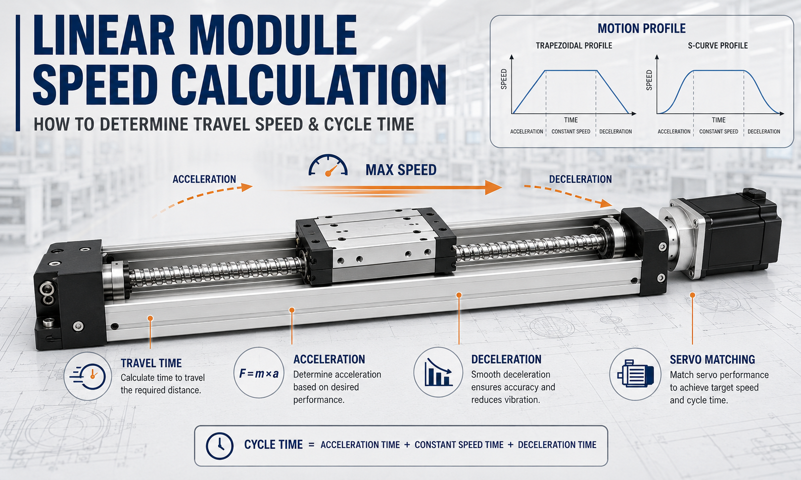
Linear module speed calculationis not simply a matter of dividing travel distance by motion time, and the achievable speed cannot be determined from the motor's rated speed alone. A complete calculation must consider stroke, target cycle time, acceleration, deceleration, motion profile, transmission type, moving mass, motor speed and the mechanical limits of the assembled axis.
The actual travel speed of alinear moduleis determined by the drive mechanism, motor and control system together. The motor supplies rotational speed and torque, while a ball screw, timing belt, rack and pinion or linear motor produces linear motion. The guide system carries the load and maintains motion accuracy, and the controller manages acceleration, constant-speed travel, deceleration and final positioning.
This guide explains how to calculate theoretical linear speed, acceleration distance, deceleration distance, travel time and required motor speed. It also covers triangular, trapezoidal and S-curve motion profiles, as well as the maximum-speed limits associated with different linear module drive systems.
What Must a Linear Module Speed Calculation Determine?
A complete speed calculation should do more than produce a maximum-speed value. It must determine whether the axis can accelerate, travel, decelerate and settle within the available stroke and required cycle time.
The calculation should answer the following questions:
- What average speed and peak speed are required for the specified stroke and travel time?
- Is there enough distance for the axis to complete acceleration and deceleration?
- Will the motion use a triangular or trapezoidal velocity profile?
- What rotational speed is required from the ball screw, pulley, pinion or motor?
- Can the motor provide sufficient torque at the required rotational speed?
- Are the ball screw critical speed, belt linear-speed limit and gear meshing speed acceptable?
- How much additional time will an S-curve profile add?
- Have acceleration, deceleration, settling, process and waiting time all been included in the machine cycle?
Calculation path:define the stroke, target time and motion profile; calculate acceleration distance, deceleration distance and peak speed; convert linear speed into transmission and motor speed; and finally verify the motor, drive mechanism, guide system and controller limits.
Define the Calculation Inputs
Before beginning the calculation, define the actual operating conditions of the axis. In addition to travel distance and target speed, consider payload, mounting orientation, process actions, dwell time and the motion-profile settings used by the controller.
| Symbol | Meaning | Typical Unit |
|---|---|---|
| L | Effective travel distance | mm |
| t | Travel time | s |
| v | Linear travel speed | mm/s or m/s |
| vmax | Peak speed reached during the move | mm/s |
| a | Acceleration | mm/s² or m/s² |
| d | Deceleration magnitude | mm/s² or m/s² |
| facing | Acceleration time | s |
| tc | Constant-speed time | s |
| td | Deceleration time | s |
| on | Acceleration distance | mm |
| Sc | Constant-speed distance | mm |
| Sd | Deceleration distance | mm |
| n | Ball screw, pulley, pinion or motor speed | rpm |
| p | Ball screw lead | mm/rev |
| z | Number of timing pulley teeth | Teeth |
| Pb | Timing belt pitch | mm |
| D | Pulley or pinion pitch diameter | mm |
| m | Total moving mass | kg |
| F | Required drive thrust | N |
Use consistent units throughout the calculation. For example, if speed is expressed in mm/s, travel distance and acceleration should normally be expressed in mm and mm/s². Unit inconsistency is one of the most common causes of incorrect motion calculations.
Distinguish Average Speed, Peak Speed and Maximum Allowable Speed
Average speed, peak speed and maximum allowable speed describe different values and should not be used interchangeably.
Average Speed
If acceleration, deceleration and dwell time are ignored, average speed can be estimated as:
v_average = L / t
This formula is suitable only for an initial estimate. In a positioning move, the axis cannot reach maximum speed instantly, so the required peak speed is normally higher than the calculated average speed.
Peak Speed
Peak speed is the highest actual linear speed reached during one move. It depends on travel distance, acceleration, deceleration, target travel time and the selected motion profile.
During a short move, the axis may have to begin decelerating immediately after acceleration. In this case, it does not reach the maximum speed entered in the controller.
Maximum Allowable Speed
Maximum allowable speed is the reliable operating limit of the complete mechanical and control system. It should be based on the lowest verified limit:
v_allowable = min(motor-speed limit, transmission limit, guide limit, bearing limit, controller limit, process-stability limit)
The actual commanded speed should also retain margin for temperature, lubrication condition, payload variation, mounting error and long-term wear.
How Acceleration Affects Travel Time
Acceleration determines how much time and distance the axis requires to reach the target speed. Increasing acceleration shortens the acceleration period, but also increases motor thrust, transmission load, guide moment and structural vibration.
When accelerating from rest to speedv:
where = v / a
The acceleration distance is:
Sa = v² / (2a)
The inertial force generated during acceleration is:
F_inertia = ma
F_inertia = ma
If the payload center of gravity is above or offset from the carriage, the inertial force also generates a dynamic moment:
M_dynamic = F_inertia × e
Acceleration should therefore be checked against motor peak torque, transmission capacity, allowable guide moment and mounting-structure rigidity rather than being selected from cycle time alone.
Deceleration and Braking Conditions
Deceleration determines the time and distance required to reduce the axis from its travel speed to zero. Although acceleration and deceleration use similar motion equations, their motor operating conditions and mechanical effects are not identical.
When reducing speedvto zero:
td = v / d
The deceleration distance is:
Sd = v² / (2d)
The magnitude of the inertial force generated during deceleration is:
F_deceleration = md
During deceleration, the inertial force acts opposite to the direction of travel. On a horizontal axis, the motor normally absorbs the kinetic energy of the load. On a vertical axis, upward deceleration and downward deceleration must also be evaluated with gravity included.
Excessive deceleration can cause:
- Insufficient motor peak braking torque
- Servo drive overvoltage or regenerative alarms
- Timing belt tooth impact or tooth jumping
- Shock loading of the ball screw, coupling and bearings
- Payload movement or fixture slippage
- Vibration in the module body or mounting structure
- Longer settling time after the axis stops
Normal production deceleration and emergency-stop deceleration should be defined separately. Emergency stopping is a safety condition and should not automatically use the same settings as the normal motion cycle.
Determine Whether the Motion Profile Is Triangular or Trapezoidal
Common linear module velocity profiles include triangular, trapezoidal and S-curve profiles. Triangular and trapezoidal profiles can be calculated using basic constant-acceleration equations.
Trapezoidal Motion Profile
A trapezoidal profile contains acceleration, constant-speed and deceleration segments. The axis accelerates to the commanded speed, travels at that speed for a defined distance and then decelerates to zero.
For a target peak speedv, accelerationaand decelerationd:
Sa = v² / (2a)
Sd = v² / (2d)
If:
Sa + Sd ≤ L
the move has enough distance to complete acceleration and deceleration, and a constant-speed segment may exist.
The constant-speed distance is:
Sc = L - Sa - Sd
The corresponding times are:
where = v / a
tc = Sc / v
td = v / d
Total travel time is:
t_total = ta + tc + td
Triangular Motion Profile
If the required acceleration and deceleration distances exceed the available travel, the axis cannot reach the commanded maximum speed. The motion becomes triangular, with the axis beginning deceleration immediately after reaching its actual peak speed.
When the initial and final speeds are both zero, the actual peak speed is:
v_peak = √[2Lad / (a + d)]
The acceleration and deceleration times are:
ta = v_peak / a
td = v_peak / d
Total travel time is:
t_total = ta + td
When acceleration and deceleration are equal, so thata = d, the equations simplify to:
v_peak = √(aL)
t_total = 2√(L / a)
S-Curve Profiles and Jerk Limitation
An S-curve profile limits the rate at which acceleration changes. This rate is known as jerk. By smoothing the transitions into and out of acceleration and deceleration, an S-curve can reduce mechanical shock, structural vibration, timing belt deformation and payload oscillation.
S-curve motion is particularly useful for:
- High-center-of-gravity or overhung loads
- Liquid handling and unstable materials
- Vision inspection and precision positioning
- High-speed pick-and-place systems
- Flexible multi-axis structures
- Applications requiring short settling time
Under the same maximum speed and acceleration limits, an S-curve profile usually requires more distance or time than an ideal trapezoidal profile. Actual travel time should therefore be recalculated or simulated using the controller's jerk setting, smoothing time or S-curve percentage.
Convert Linear Speed for Different Drive Systems
After calculating the required linear speed, convert it into the rotational speed of the transmission and motor. The conversion method depends on the linear module drive type.
Ball Screw Linear Module
Each ball screw revolution moves the carriage by one screw lead. Linear speed is calculated as:
v = np / 60
Where:
- vis linear speed in mm/s.
- nis ball screw rotational speed in r/min.
- pis ball screw lead in mm/rev.
To calculate the required screw speed from the target linear speed:
n = 60v / p
For example, with a target speed of 1000 mm/s and a ball screw lead of 20 mm/rev:
n = 60 × 1000 / 20 = 3000 r/min
After calculating the required screw speed, verify:
- Maximum allowable motor speed
- Ball screw critical speed
- Screw diameter and unsupported length
- Ball screw support arrangement
- Ball nut speed or DN-value limit
- Bearing allowable speed
- Vibration, noise and temperature rise at high speed
A long ball screw may experience vibration, bending or whipping at high rotational speed. Meeting the theoretical motor-speed requirement does not prove that the assembled screw system can operate safely.
Timing Belt Linear Module
For a timing belt drive, the linear travel per pulley revolution equals the number of pulley teeth multiplied by the belt pitch:
v = zPb n / 60
Where:
- zis the number of teeth on the drive pulley.
- Pbis the timing belt pitch in mm.
- nis the drive pulley speed in r/min.
If the pulley pitch diameter is known, linear speed can also be calculated as:
v = πDn / 60
The maximum speed of atiming belt moduleis also limited by:
- Allowable belt linear speed
- Number of engaged pulley teeth
- Belt tooth shear capacity
- Belt pretension
- Long-stroke belt vibration
- Pulley and bearing speed limits
- Elastic belt stretch during rapid reversal
Rack and Pinion Linear Module
For a rack and pinion drive, linear speed can be calculated from the pinion pitch diameter:
v = πDn / 60
If a gearbox is installed between the motor and pinion, first calculate the actual pinion speed from the motor speed and gearbox ratio.
Rack and pinion speed limits may depend on:
- Maximum motor and gearbox speed
- Pinion pitch-line velocity
- Gear tooth contact strength
- Rack and pinion meshing accuracy
- High-speed operating noise
- Lubrication condition
- Long-stroke installation straightness
Linear Motor Module
A linear motor does not use a ball screw, belt or rack to convert rotary motion into linear travel. Its speed is primarily limited by the motor's electromagnetic capability, servo drive output, encoder feedback frequency, guide performance and cable system.
Linear motors can provide high speed and acceleration, but the design must still verify continuous thrust, peak thrust, coil temperature, magnet-track length, feedback resolution and the allowable speed of moving cables.
Calculate Drive Thrust and Motor Requirements
After defining the speed profile, calculate the force required to produce the specified acceleration. For a horizontal axis, a general force model is:
F_horizontal = ma + F_friction + F_cable + F_process
For upward acceleration on a vertical axis:
F_vertical = m(g + a) + F_friction + F_process
Higher required thrust produces higher peak motor torque. For a ball screw drive, linear thrust can be converted into screw torque using:
T_screw = Fp / (2πη)
Whereoris transmission efficiency. The screw leadpmust be expressed in m/rev to obtain a torque result in N·m.
Servo motor matching should not be based on rated power alone. Verify:
- Peak torque during acceleration and deceleration
- RMS torque over the complete cycle
- Motor speed required for the target linear speed
- Available motor torque at the required speed
- Motor-to-load inertia ratio
- Regenerative energy during deceleration
- Brake requirements for vertical axes
- Encoder, servo drive and controller compatibility
A motor may provide adequate torque at low speed but become unable to produce the required torque near its maximum speed. Final verification should therefore use the actual motor speed-torque curve.
Worked Linear Module Speed Calculation Example
The following example demonstrates how to calculate speed, travel time and ball screw rotational speed. All values are hypothetical and are provided only to explain the engineering method. They do not represent a specific QRXQ product model or customer application.
Operating Conditions
| Parameter | Value |
|---|---|
| Effective travel distance | 800 mm |
| Commanded maximum speed | 1000 mm/s |
| Acceleration | 2500 mm/s² |
| Deceleration | 2500 mm/s² |
| Ball screw lead | 20 mm/rev |
| Initial speed | 0 mm/s |
| Final speed | 0 mm/s |
Step 1: Calculate Acceleration Time
where = v / a
ta = 1000 / 2500 = 0.4 s
Step 2: Calculate Acceleration Distance
Sa = v² / (2a)
At = 1000² / (2 × 2500) = 200 mm
Step 3: Calculate Deceleration Time and Distance
Because acceleration and deceleration are equal:
td = 1000 / 2500 = 0.4 s
Sd = 1000² / (2 × 2500) = 200 mm
Step 4: Determine the Motion Profile
Sa + Sd = 200 + 200 = 400 mm
The total travel is 800 mm, so 400 mm remains for constant-speed motion:
Sc = 800 - 200 - 200 = 400 mm
BecauseScis greater than zero, the motion uses atrapezoidal velocity profile.
Step 5: Calculate Constant-Speed Time
tc = Sc / v
tc = 400 / 1000 = 0.4 s
Step 6: Calculate Total Travel Time
t_total = ta + tc + td
t_total = 0.4 + 0.4 + 0.4 = 1.2 s
Under ideal conditions, without S-curve smoothing, controller delay or settling time, the theoretical travel time is1.2 seconds.
Step 7: Calculate Ball Screw Speed
n = 60v / p
n = 60 × 1000 / 20 = 3000 r/min
The ball screw and a directly coupled motor must therefore reach approximately3000 r/min.
Step 8: Complete the Speed-Limit Check
| Calculated Requirement | Result | Catalog or Design Check |
|---|---|---|
| Peak linear speed | 1000 mm/s | Module maximum allowable speed |
| Acceleration distance | 200 mm | Available stroke and limit positions |
| Deceleration distance | 200 mm | Normal and emergency stopping distance |
| Theoretical travel time | 1.2 s | Actual controller motion profile |
| Ball screw speed | 3000 r/min | Critical speed, DN value and bearing speed |
| Motor speed | Approximately 3000 r/min | Maximum motor speed and high-speed torque |
Even if the motor can operate at 3000 r/min, the design cannot yet be approved. The calculation must also verify the ball screw critical speed for the actual screw length and support arrangement, the ball nut speed limit, guide lubrication, motor torque at high speed and vibration of the assembled module.
Short-Stroke Triangular Motion Example
Assume the same acceleration, deceleration and maximum-speed settings are used, but the effective travel is reduced to 200 mm:
Sa + Sd = 400 mm > 200 mm
The move does not have enough distance to reach 1000 mm/s, so the motion becomes triangular.
Because acceleration and deceleration are equal:
v_peak = √(aL)
v_peak = √(2500 × 200) = 707.1 mm/s
Acceleration time is:
ta = 707.1 / 2500 = 0.283 s
Deceleration time is equal, so:
t_total = 0.283 + 0.283 = 0.566 s
The corresponding ball screw speed is:
n = 60 × 707.1 / 20 = 2121.3 r/min
This example shows that even when the controller is set to 1000 mm/s, a short-stroke move may reach only approximately 707 mm/s because the available acceleration and deceleration distance is insufficient.
Additional Time Required in a Complete Machine Cycle
Theoretical linear module travel time is usually only one part of the complete equipment cycle. Actual machine-cycle time may also include:
- Controller command response time
- Additional time caused by S-curve smoothing
- Position settling time
- Gripper opening and closing time
- Vacuum generation and confirmation time
- Camera exposure and vision-processing time
- Dispensing, welding or pressing process time
- Sensor confirmation time
- Inter-axis waiting and interlock time
- Return-to-home or empty-return travel
The complete machine cycle can therefore be expressed as:
t_cycle = t_motion + t_settling + t_process + t_waiting + t_return
Calculating cycle time by dividing travel distance by maximum speed will usually underestimate the actual operating time.
Common Linear Module Speed Calculation Mistakes
- Dividing travel distance by maximum speed without including acceleration and deceleration.
- Treating average speed as the peak speed reached during the move.
- Failing to determine whether the profile is triangular or trapezoidal.
- Assuming the commanded controller speed is always reached.
- Checking only maximum motor speed without checking available torque at that speed.
- Calculating an acceptable ball screw speed without checking critical speed and DN limits.
- Checking only pulley speed on a timing belt module while ignoring belt speed, tooth engagement and vibration.
- Ignoring regenerative energy and servo-drive overvoltage during deceleration.
- Using the same thrust calculation for horizontal and vertical axes.
- Ignoring dynamic moments caused by an offset payload center of gravity.
- Using an ideal trapezoidal profile calculation while strong S-curve smoothing is enabled in the controller.
- Failing to verify speed, temperature, vibration and positioning under the real payload.
Information Required for Linear Module Speed Selection
Prepare the following information before completing a practical linear module speed calculation:
- Effective travel distance
- Target one-way travel time and complete machine cycle
- Initial and final speed
- Target maximum speed
- Acceleration and deceleration
- S-curve or jerk setting
- Total moving mass
- Payload center-of-gravity position
- Horizontal, vertical or inclined mounting orientation
- External process force
- Ball screw lead or pulley and pinion parameters
- Motor maximum speed and speed-torque curve
- Gearbox ratio and efficiency
- Positioning accuracy and settling-time requirements
- Daily duty cycle and continuous operating time
- Temperature, contamination, lubrication and maintenance conditions
Engineering Takeaway
A reliablelinear module speed calculationmust connect travel distance, target cycle time, acceleration, deceleration and transmission parameters. The maximum speed listed in a catalog is only one product limit and does not directly represent the speed that a machine can achieve over a specific stroke and payload.
First determine whether the move uses a triangular or trapezoidal profile. Then calculate peak speed, acceleration distance, deceleration distance and theoretical travel time. Convert the required linear speed into ball screw, pulley, pinion or motor speed, and verify motor torque at speed, transmission limits, guide performance and the actual controller profile.
The final result should be confirmed under the real payload and documented with the input values, units, motion profile, formulas, catalog limits, design margins and acceptance method. This keeps the speed-selection result traceable during machine design, commissioning, maintenance and future cycle-time optimization.
