 English

Gear racklinear modulesare widely used in industrial automation systems that require long travel, high speed, heavy load capacity and reliable continuous operation. Unlikeball screw modules, which are generally limited by screw length, rotational speed and critical-speed considerations, rack-and-pinion systems transmit motion through a rotating gear that engages with a linear rack.
This transmission method allows a gear rack linear axis to be extended over several meters while maintaining stable speed and load performance. It is therefore especially suitable forgantry robots, automated production lines, material-handling equipment, welding systems, CNC loading equipment and other large-scale motion applications.
The main gear rack linear module features include long stroke, high speed, heavy load capacity, high rigidity, modular extension, high acceleration, stable transmission, multi-axis compatibility and industrial durability.
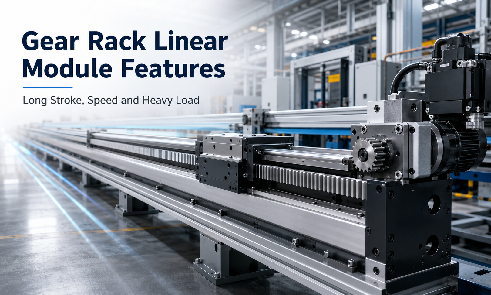
1. Long-Stroke Motion Capability
Long travel is one of the most important advantages of a gear rack linear module. A ball screw must normally be manufactured as one continuous precision shaft, so increasing its length also increases manufacturing difficulty, installation complexity and the risk of screw vibration.
A gear rack system uses rack sections installed along the machine base. Multiple rack sections can be accurately connected to create a continuous transmission path. This modular structure makes it possible to build linear axes with strokes of several meters or even longer.
Long-stroke rack and pinion actuators are commonly used in:
- Large gantry robots
- Automatic welding lines
- Long-distance material transfer systems
- CNC machine loading and unloading
- Laser cutting and processing equipment
- Warehouse and logistics automation
- Large-format inspection systems
The actual stroke is determined mainly by the machine structure, rack installation length, guide rail arrangement, cable routing and control-system requirements rather than by the length of a rotating screw.
2. High Linear Speed
Gear rack linear modules can achieve high linear speeds because the transmission does not depend on a long screw rotating at high speed. The motor drives a pinion through a gearbox or direct coupling, and the rotational motion of the pinion is converted into linear movement along the rack.
The achievable speed depends on several factors:
- Servo motor rated speed
- Pinion pitch diameter
- Gearbox reduction ratio
- Rack and pinion accuracy grade
- Guide rail speed capability
- Lubrication condition
- Moving load and acceleration requirements
Compared with long ball screw axes, a high-speed rack-driven axis is less affected by screw whip and critical rotational speed. This makes rack transmission a practical choice for applications requiring both long travel and short cycle times.
3. Heavy Load Capacity
Gear rack modules are suitable for transporting heavy workpieces, tooling, robot arms and industrial fixtures. The rack and pinion transmit force through direct tooth engagement, while the linear guide system supports the weight and external moments applied to the carriage.
The load capacity of a complete module depends not only on the rack but also on:
- Rack module and tooth size
- Pinion diameter and tooth width
- Gearbox output torque
- Motor torque
- Linear guide size and quantity
- Carriage dimensions
- Base structure rigidity
- Load position and overhang distance
For heavy-duty applications, larger rack modules, wider tooth surfaces, reinforced carriages and multiple guide blocks may be used. Dual-drive systems can also be installed on wide gantry structures to distribute the load across both sides.
4. High Structural Rigidity
High rigidity is essential when a linear axis carries heavy loads or experiences strong acceleration, deceleration and machining forces. Gear rack modules are commonly designed with reinforced aluminum profiles or steel bases, large linear guides and rigid motor mounting structures.
A rigid structure helps reduce:
- Carriage deformation
- Guide rail deflection
- Transmission vibration
- Positioning deviation under load
- Oscillation during acceleration and stopping
The final rigidity of the system depends on the module body, mounting surface, guide spacing, carriage length and support structure. Even a high-capacity rack actuator can lose accuracy if it is installed on an uneven or flexible machine frame.
5. Modular Extension
Modular extension is another important gear rack linear module characteristic. Rack sections, guide rails, aluminum profiles and cable-management components can be assembled according to the required travel length.
This modular design provides several benefits:
- Flexible stroke configuration
- Easier transportation of long-axis components
- Simplified replacement of damaged rack sections
- Convenient machine expansion
- Reduced dependence on one-piece transmission components
During installation, the connection between adjacent rack sections must be accurately aligned. Incorrect tooth spacing at the joint can cause impact, noise, vibration and uneven motion when the pinion passes across the connection point.
6. High Acceleration Performance
A gear rack module can provide high acceleration when matched with a suitable servo motor and gearbox. Because there is no long rotating screw, the system can avoid the high rotational inertia associated with large-diameter, long-length ball screws.
High acceleration is especially valuable in applications with frequent start-stop cycles, such as:
- Automated pick-and-place systems
- High-speed sorting equipment
- Packaging lines
- Production-line transfer units
- Robot gantry systems
However, acceleration should not be selected based only on motor capability. The moving mass, rack tooth force, gearbox torque, guide block load, machine vibration and stopping distance must also be considered.
Excessive acceleration can increase tooth impact, structural vibration and servo following error. A suitable S-curve acceleration profile is often used to produce smoother motion and reduce mechanical shock.
7. Stable Transmission Over Long Distances
Rack and pinion transmission provides stable mechanical engagement over long travel distances. When the rack is correctly aligned and properly lubricated, the pinion can continuously transmit force without the stroke limitations associated with a screw shaft.
Stable transmission depends on several installation and maintenance conditions:
- Correct rack straightness
- Uniform tooth engagement
- Proper pinion preload
- Accurate guide rail alignment
- Suitable lubrication
- Rigid motor and gearbox mounting
Helical racks are often selected when smoother engagement, lower noise and higher load-sharing capability are required. Straight racks are structurally simpler and may be suitable for general industrial positioning applications.
For applications requiring reduced backlash, the system may use precision-ground racks, high-accuracy gearboxes or dual-pinion preload mechanisms.
8. Multi-Axis System Compatibility
Gear rack modules can be integrated into XY, XZ, XYZ and gantry motion systems. Their long-stroke and heavy-load characteristics make them particularly suitable for the main horizontal axis of large automation equipment.
Typical multi-axis configurations include:
- A rack-driven X axis with a ball screw Z axis
- Dual rack-driven axes for a wide gantry
- Rack-driven X and Y axes for large-area positioning
- A long rack axis combined with belt or screw-driven secondary axes
- Multi-carriage systems operating on one long base
Different transmission technologies can therefore be combined within the same machine. A rack-driven axis may provide long-distance travel, while a ball screw or linear motor handles shorter, higher-precision movement.
9. Industrial Durability
Gear rack linear modules are designed for demanding industrial environments and repeated operating cycles. Rack teeth, pinions, bearings, guide rails and structural components can be selected according to the required duty cycle and environmental conditions.
Industrial durability depends on:
- Rack and pinion material
- Tooth surface hardening
- Gearbox quality
- Bearing capacity
- Lubrication system
- Dust and debris protection
- Operating load and duty cycle
- Preventive maintenance frequency
For dusty or debris-producing environments, protective covers, bellows, wipers or automatic lubrication systems may be added. Regular inspection of tooth wear, backlash, lubrication and mounting bolts helps maintain long-term transmission reliability.
Performance Overview
| Feature | Engineering Benefit | Typical Application Value |
|---|---|---|
| Long stroke | Rack sections can be extended along the machine base | Suitable for multi-meter travel |
| High speed | No long rotating screw or screw-whip limitation | Shorter transfer and production cycles |
| Heavy load | High tooth force and reinforced guide support | Moves large workpieces and tooling |
| High rigidity | Rigid base, carriage and guide arrangement | Improved stability under dynamic loads |
| Modular extension | Multiple rack and base sections can be connected | Flexible machine layout and expansion |
| High acceleration | Efficient servo and gearbox transmission | Suitable for frequent start-stop cycles |
| Stable transmission | Continuous rack and pinion engagement | Reliable motion over long distances |
| Multi-axis compatibility | Can be combined with screw, belt and linear motor axes | Supports XY, XZ, XYZ and gantry systems |
| Industrial durability | Hardened transmission parts and maintainable structure | Suitable for continuous production environments |
Gear Rack Modules Compared with Other Linear Modules
| Comparison Item | Gear Rack Module | Ball Screw Module | Timing Belt Module |
|---|---|---|---|
| Typical stroke | Very long | Short to medium | Medium to long |
| Load capacity | High to very high | Medium to high | Low to medium |
| Speed | High | Medium | High |
| Positioning accuracy | Medium to high, depending on rack grade | High | Medium |
| Rigidity | High | High | Medium |
| Modular extension | Excellent | Limited | Good |
| Maintenance requirement | Regular tooth lubrication and inspection | Regular screw lubrication | Belt tension and wear inspection |
Important Selection Considerations
Although gear rack modules provide strong performance for long-stroke and heavy-duty motion, the module should be selected according to the complete operating conditions.
Key selection parameters include:
- Required effective stroke
- Maximum payload
- Load center and overhang distance
- Required speed and acceleration
- Positioning and repeatability requirements
- Horizontal, vertical or inclined installation
- Operating cycle and daily running time
- Environmental dust, moisture and temperature
- Required gearbox ratio and motor power
- Single-drive or dual-drive gantry configuration
For a dual-drive gantry, both sides must remain synchronized. Servo control, mechanical alignment and homing procedures must be designed to prevent gantry skew and uneven loading.
Accuracy and Backlash Considerations
Gear rack modules can provide reliable industrial positioning, but their accuracy depends on the quality of the complete transmission chain. Rack pitch error, gearbox backlash, pinion clearance, guide straightness and structural deformation all contribute to the final positioning result.
Accuracy can be improved through:
- High-precision ground racks
- Low-backlash planetary gearboxes
- Helical rack and pinion engagement
- Dual-pinion preload systems
- Linear encoder feedback
- Servo compensation and calibration
- Rigid installation surfaces
Applications requiring extremely high precision should evaluate not only the nominal rack accuracy but also the total accumulated error over the full travel length.
Maintenance Requirements
Proper maintenance helps preserve the speed, accuracy and service life of a heavy-duty rack actuator. Recommended maintenance tasks include:
- Cleaning dust and debris from rack teeth
- Applying suitable gear lubricant
- Checking pinion and rack wear
- Inspecting backlash and preload
- Checking gearbox mounting bolts
- Inspecting guide rail lubrication
- Verifying rack joint alignment
- Monitoring abnormal noise and vibration
Maintenance intervals should be adjusted according to speed, load, operating hours and environmental contamination.
Conclusion
Gear rack linear modules combine long stroke, high speed, heavy load capacity, high rigidity and modular extension in one industrial motion platform. They are particularly effective when a machine requires travel distances that are difficult to achieve with conventional ball screw systems.
Their compatibility with servo motors, gearboxes, multi-axis structures and dual-drive gantries makes them suitable for large automation systems, material handling equipment and continuous production lines.
To obtain reliable performance, engineers must correctly select the rack size, gearbox ratio, motor torque, guide system and structural support. Accurate installation, proper lubrication and regular inspection are equally important for maintaining stable transmission, positioning performance and industrial durability throughout the service life of the module.
