 English

Agear rack linear moduleis a mechanical linear motion system that converts the rotary motion of a motor into long-stroke linear movement through the engagement of a pinion and a gear rack. It is commonly used in industrial automation equipment requiring long travel, high speed, heavy load capacity and continuous reciprocating operation.
Unlike aball screw linear module, which transfers force through a rotating screw and nut, a rack-driven linear axis uses a small rotating gear to move along a straight gear rack. This transmission method is not significantly limited by screw critical speed, making it particularly suitable for long production lines,gantry robots, material handling systems, machining equipment and large-format automation platforms.
A complete gear rack linear module is not composed only of a rack and pinion. It normally integrates a gearbox, servo motor, linear guide, guide blocks, carriage, bearings, lubrication unit, sensors, end stops and protective components. Each component performs a specific mechanical, transmission, positioning, monitoring or safety function.
This article explains the maingear rack linear module components, their functions, how they work together and what engineers should consider when selecting or maintaining a rack-driven linear axis.
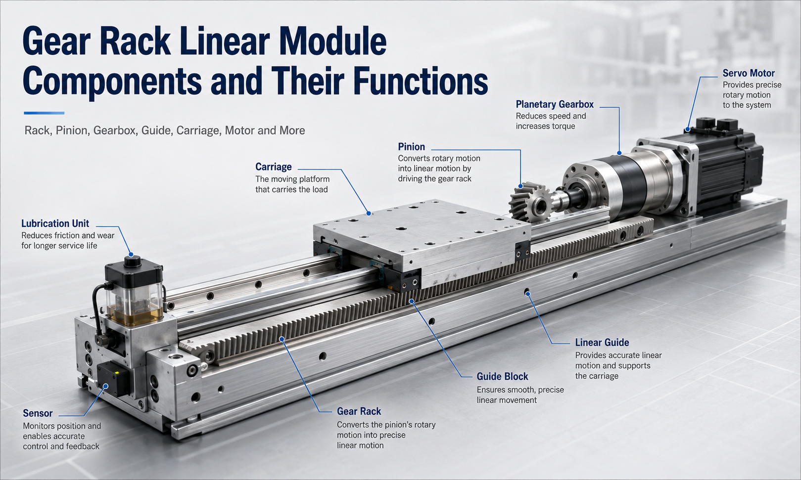
Main Components of a Gear Rack Linear Module
The typical components of a gear rack linear module include:
- Gear rack
- Pinion
- Planetary gearbox
- Linear guide
- Guide blocks
- Carriage
- Servo motor
- Bearings and support components
- Lubrication unit
- Position and limit sensors
- Mechanical end stops
- Protective covers and sealing components
Although each component has an independent function, the operating performance of the linear module depends on how accurately these parts are manufactured, assembled, aligned and controlled as a complete system.
Gear Rack
Thegear rackis a straight mechanical component with a series of evenly spaced teeth along its length. It acts as the fixed or moving linear transmission element of the rack-and-pinion system.
In most rack-drivenlinear modules, the rack is fixed along the base frame while the motor, gearbox and pinion are installed on the moving carriage. As the pinion rotates, it engages with the rack teeth and drives the carriage along the linear guide.
Main Functions of the Gear Rack
- Provides a continuous toothed path for linear movement
- Transfers the tangential force generated by the pinion
- Supports long-stroke travel through multiple connected rack sections
- Determines part of the module’s load capacity and positioning performance
- Allows the drive unit to travel over distances much longer than conventional screw-driven systems
The rack must be installed parallel to the linear guide. If the rack is misaligned, the pinion may engage unevenly, causing vibration, noise, tooth wear, increased backlash or excessive load on the gearbox bearings.
Straight and Helical Gear Racks
Straight racks have teeth perpendicular to the direction of motion. They have a relatively simple structure and are widely used in general industrial applications.
Helical racks use angled teeth. More than one tooth can remain in contact during operation, which can improve load distribution, reduce transmission noise and produce smoother movement. However, helical gearing also generates axial force, so the bearing and gearbox arrangement must be designed to support the additional load.
Segmented Rack Installation
For very long travel distances, several rack sections can be connected end to end. The tooth pitch at each joint must remain continuous. Poor joint alignment can create impact when the pinion passes from one rack section to another.
Precision installation tools or reference racks are commonly used to maintain correct tooth spacing at the joint. The mounting surface must also be straight and stable to prevent local deformation.
Pinion
Thepinionis the circular gear that meshes with the gear rack. It is connected to the output shaft of the gearbox or directly to the motor in some lower-load applications.
When the servo motor rotates, the gearbox reduces the speed and increases the output torque. The resulting rotation is transferred to the pinion. The pinion teeth push against the rack teeth, converting rotary motion into linear displacement.
Main Functions of the Pinion
- Converts gearbox output rotation into linear movement
- Transfers driving torque to the gear rack
- Determines the linear travel per revolution
- Influences output speed, thrust and positioning resolution
- Maintains continuous mechanical engagement with the rack
The pitch, pressure angle, tooth profile and module of the pinion must match the gear rack. A mismatched pinion and rack cannot engage correctly and may cause immediate tooth damage.
Pinion Diameter and Motion Performance
A larger pinion produces more linear travel for each revolution, which can increase the axis speed. However, it also requires more torque to generate the same linear force.
A smaller pinion provides less travel per revolution and can generate greater linear force for a given torque, but the rotational speed of the motor and gearbox may need to increase to achieve the required linear velocity.
The pinion size should therefore be selected together with the motor speed, gearbox ratio, required thrust, travel speed and positioning resolution.
Backlash Between Rack and Pinion
A small clearance is normally required between the rack and pinion teeth to prevent binding. However, excessive clearance creates transmission backlash, which may reduce bidirectional positioning accuracy.
High-precision systems may use an adjustable pinion mounting structure, spring-loaded preload, dual-pinion arrangement or electronic compensation to reduce the effect of backlash.
Planetary Gearbox
Theplanetary gearboxis installed between the servo motor and pinion. It reduces the motor speed while increasing the output torque available to drive the rack.
A servo motor may operate efficiently at several thousand revolutions per minute, while a rack-driven axis often requires lower pinion speed and higher torque. The gearbox adapts the motor output to the mechanical requirements of the linear axis.
Main Functions of the Planetary Gearbox
- Reduces motor rotational speed
- Increases output torque
- Improves the effective positioning resolution of the axis
- Matches motor performance to the required linear speed and thrust
- Supports radial, axial and moment loads generated at the pinion
- Provides a compact connection between the motor and transmission system
Gearbox Ratio
A higher reduction ratio produces lower pinion speed and higher output torque. This is useful for heavy-load or high-thrust applications. However, an excessively high reduction ratio can limit the maximum travel speed.
A lower reduction ratio supports higher axis speed but provides less torque multiplication. The correct ratio depends on the moving mass, friction, acceleration, external resistance, required speed and duty cycle.
Gearbox Backlash
Gearbox backlash is one of the mechanical factors affecting the positioning accuracy of a gear rack linear module. Precision planetary gearboxes generally provide lower backlash than standard industrial gearboxes.
The required gearbox grade should be selected according to the application. A general material handling axis may tolerate more backlash than a machining, dispensing, inspection or precision positioning system.
Linear Guide
Thelinear guidesupports and guides the moving carriage. It controls the direction of movement and prevents the carriage from rotating, lifting or moving sideways under load.
The rack and pinion system generates the driving force, but it is not intended to provide accurate linear guidance. That function is performed by the linear guide and guide blocks.
Main Functions of the Linear Guide
- Defines a straight and stable motion path
- Supports the weight of the carriage and payload
- Resists radial, lateral and moment loads
- Maintains alignment between the moving carriage and base
- Reduces rolling resistance during movement
- Helps maintain positioning and repeatability performance
The guide rail must be installed straight and parallel to the gear rack. Any significant parallelism error can cause the pinion engagement depth to change as the carriage moves along the axis.
Single-Rail and Dual-Rail Arrangements
A compact gear rack module may use one wide linear guide with multiple guide blocks. Larger or heavier systems often use two parallel guide rails to increase moment resistance and carriage stability.
Dual-rail systems are particularly useful when the payload has a high center of gravity, a large overhang or significant pitching, yawing or rolling moments.
Guide Blocks
Theguide blocksare rolling elements mounted on the linear guide rail. They contain recirculating balls or rollers that allow the carriage to move with relatively low friction.
The guide blocks are normally fixed to the underside of the carriage. As the carriage moves, the rolling elements circulate within the block and maintain contact with the guide rail raceways.
Main Functions of Guide Blocks
- Connect the moving carriage to the linear guide
- Carry vertical and horizontal loads
- Resist overturning moments
- Provide smooth and repeatable linear motion
- Maintain rigidity between the carriage and module base
The number, spacing, preload and size of the guide blocks directly affect load capacity and rigidity. Increasing the distance between guide blocks can improve resistance to moment loads, but it also increases the required carriage length.
Guide Block Preload
Preloaded guide blocks reduce internal clearance and improve rigidity. However, excessive preload increases friction and may reduce service life.
The appropriate preload level should be selected according to the required accuracy, vibration resistance, load condition and operating speed.
Carriage
Thecarriage, also called the moving table or slider, is the main moving platform of the gear rack linear module. It connects the guide blocks, drive system and customer payload into one moving assembly.
Main Functions of the Carriage
- Provides a mounting surface for tools, fixtures or workpieces
- Transfers driving force from the pinion to the payload
- Connects the motor, gearbox and pinion to the guide system
- Distributes external loads across the guide blocks
- Maintains the structural relationship between transmission and guidance components
The carriage must have sufficient rigidity to prevent bending or torsional deformation. If the carriage deforms under load, the guide blocks may be loaded unevenly and the pinion-to-rack engagement may change.
Carriage Mounting Surface
The mounting surface usually includes threaded holes, locating holes or T-slots. The payload should be mounted securely without interfering with sensors, lubrication lines, covers or cable management components.
Heavy or offset loads should be evaluated according to the allowable static and dynamic moment ratings of the module.
Servo Motor
Theservo motorprovides the controlled rotary power required to move the linear axis. It normally includes an encoder that reports motor position and speed to the servo drive.
Themotion controllersends a position, speed or torque command to the servo drive. The drive controls the motor current and continuously compares the command with encoder feedback.
Main Functions of the Servo Motor
- Provides rotational torque to the gearbox and pinion
- Controls travel speed and acceleration
- Supports precise start, stop and reversing motion
- Provides position and speed feedback through the encoder
- Allows synchronization with other automation axes
Motor Selection Considerations
Servo motor selection should consider:
- Total moving mass
- Required linear force
- Maximum travel speed
- Acceleration and deceleration
- Gearbox ratio
- Pinion pitch diameter
- Friction and external resistance
- Installation direction
- Operating duty cycle
- Emergency stopping requirements
The motor should not be selected only according to constant-speed torque. Acceleration torque, reflected inertia and peak load conditions must also be evaluated.
Bearings and Support Components
Bearingssupport rotating parts in the motor, gearbox and pinion assembly. Depending on the design, additional bearing supports may be used to stabilize the pinion shaft or absorb transmission forces.
Main Functions of Bearings
- Support rotating shafts
- Reduce friction during rotation
- Maintain pinion shaft alignment
- Carry radial and axial loads
- Limit shaft deflection under transmission force
Bearing wear may cause increased noise, vibration, radial play or irregular gear engagement. If the pinion shaft moves excessively, the tooth contact pattern can become unstable and accelerate rack and pinion wear.
Lubrication Unit
Thelubrication unitdelivers grease or oil to the rack, pinion, linear guide and guide blocks. Correct lubrication reduces friction, prevents dry contact and helps protect metal surfaces against corrosion and premature wear.
Main Functions of the Lubrication Unit
- Reduces friction between meshing gear teeth
- Limits surface wear and pitting
- Lubricates guide rail raceways and rolling elements
- Reduces heat generated by repeated movement
- Extends the service life of transmission and guidance components
- Helps prevent rust in humid environments
Manual and Automatic Lubrication
Smaller modules may use manual grease fittings. Maintenance personnel apply lubricant at scheduled intervals according to the operating distance, speed, load and environment.
Large industrial systems may use an automatic lubrication pump connected to distribution lines. The pump supplies a controlled quantity of lubricant to multiple lubrication points at regular intervals.
An automatic system can reduce maintenance workload and improve consistency, especially for long axes, high-duty-cycle equipment or locations that are difficult to access.
Effects of Incorrect Lubrication
Insufficient lubrication can cause increased noise, tooth wear, guide block damage and higher drive resistance. Excessive lubrication can attract dust, contaminate surrounding equipment and create unnecessary leakage.
The lubricant type must also be compatible with the operating temperature, speed, load and environmental conditions.
Sensors
Sensorsprovide position-related signals to the controller. Common sensor types include proximity sensors, photoelectric sensors, magnetic sensors and mechanical limit switches.
Main Functions of Sensors
- Detect the home position
- Identify positive and negative travel limits
- Confirm carriage arrival at a specified station
- Support automatic homing procedures
- Prevent the carriage from travelling beyond the permitted range
- Provide status signals to the control system
Home Sensor
The home sensor defines a repeatable reference position for the axis. When the machine starts, the carriage usually moves toward the home sensor at a controlled speed. The controller then establishes the machine coordinate reference.
Limit Sensors
Positive and negative limit sensors are installed near the ends of the usable travel. When activated, they instruct the control system to stop movement in the corresponding direction.
Limit sensors should be positioned early enough to allow the moving mass to decelerate before reaching the mechanical end stop.
Mechanical End Stops
Mechanical end stopsare physical components installed near both ends of the axis. They provide a final safety barrier if the control system or limit sensors fail.
Main Functions of End Stops
- Prevent the carriage from leaving the guide rail
- Provide emergency mechanical travel limitation
- Protect surrounding equipment from uncontrolled movement
- Reduce damage during overtravel conditions
Mechanical end stops are not intended to function as normal positioning stops. Repeated high-speed impact can damage the carriage, guide blocks, gearbox, rack or supporting structure.
Some systems use elastomer buffers, shock absorbers or hydraulic dampers to reduce impact energy.
Protective Components
Gear rack linear modules are frequently installed in environments containing dust, chips, coolant, oil mist or other contaminants.Protective componentshelp isolate critical transmission and guidance parts from these conditions.
Common Protective Components
- Sheet-metal covers
- Telescopic covers
- Bellows
- Brush seals
- Wipers
- Rack covers
- Guide rail seals
- Motor and gearbox guards
Main Functions of Protective Components
- Prevent debris from entering the rack and guide system
- Reduce lubricant contamination
- Protect operators from moving components
- Limit accidental contact with the pinion and rack
- Improve reliability in harsh industrial environments
- Reduce maintenance frequency
The protection method must be selected according to the environment. A clean assembly line may require only basic covers, while a machining application may need sealed covers, scrapers and coolant-resistant components.
How the Components Work Together
During operation, the controller sends a movement command to the servo drive. The servo drive energizes the motor and controls its rotation according to encoder feedback.
The planetary gearbox reduces the motor speed and increases the output torque. The gearbox output shaft rotates the pinion, which meshes with the fixed gear rack. The resulting tangential force moves the carriage along the linear guide.
The guide blocks carry the payload and constrain the carriage to a straight path. Sensors monitor the home position and travel limits, while the lubrication unit supplies lubricant to the gear and guide interfaces. Protective components reduce contamination and mechanical end stops provide final overtravel protection.
Because all these components operate as one integrated system, a problem in one area can affect the entire module. For example, poor guide alignment can change rack engagement, while inadequate lubrication can increase motor load and positioning error.
Component Function Summary
| Component | Primary Function | Possible Effect of Failure |
|---|---|---|
| Gear rack | Provides the linear toothed transmission path | Positioning error, noise, vibration or tooth damage |
| Pinion | Converts rotary torque into linear driving force | Backlash, uneven movement or loss of transmission |
| Planetary gearbox | Reduces speed and increases torque | Insufficient thrust, excessive backlash or abnormal noise |
| Linear guide | Defines the movement path and supports loads | Poor straightness, vibration or carriage binding |
| Guide blocks | Connect the carriage to the guide rail | Increased friction, play or reduced rigidity |
| Carriage | Supports and moves the customer payload | Deformation, unstable mounting or uneven loading |
| Servo motor | Provides controlled rotary power | Motor alarm, insufficient speed or positioning failure |
| Bearings | Support rotating shafts and transmission loads | Noise, shaft play or pinion misalignment |
| Lubrication unit | Reduces friction and component wear | Heat, premature wear or increased drive resistance |
| Sensors | Detect home, limits and operating positions | Homing failure or overtravel risk |
| End stops | Provide final mechanical travel protection | Carriage may leave the permitted travel range |
| Protective components | Prevent contamination and accidental contact | Accelerated wear and increased maintenance |
Factors Affecting Component Selection
The components of a gear rack linear module should be selected as an integrated system rather than individually. Important selection factors include:
- Payload and moving mass
- Required stroke length
- Maximum speed
- Acceleration and deceleration
- Required thrust
- Positioning and repeatability requirements
- Permissible backlash
- Installation direction
- External forces and moment loads
- Operating environment
- Daily operating cycles
- Maintenance accessibility
For example, a high-speed logistics axis may prioritize travel speed and long stroke, while a heavy machining axis may require a larger rack, higher gearbox ratio, roller guide blocks and more robust protective covers.
Common Component-Related Problems
Excessive Backlash
Excessive backlash may result from worn rack teeth, worn pinion teeth, loose mounting bolts, gearbox backlash or incorrect gear engagement. The rack and pinion engagement should be inspected before applying software compensation.
Abnormal Noise
Noise may be caused by poor lubrication, rack misalignment, damaged teeth, excessive preload, bearing wear or incorrect gearbox installation.
Uneven Movement
Uneven movement may indicate inconsistent rack joints, guide contamination, damaged guide blocks, variable pinion engagement or carriage deformation.
Increased Motor Load
Higher motor current may result from inadequate lubrication, excessive guide preload, rack misalignment, gearbox damage or external mechanical interference.
Reduced Positioning Accuracy
Reduced accuracy can be associated with mechanical backlash, loose couplings, worn gears, insufficient structural rigidity, sensor movement or incorrect servo parameters.
Maintenance of Gear Rack Linear Module Components
Routine maintenance should include inspection of the complete transmission and guide system.
- Check rack and pinion tooth surfaces for wear or damage
- Inspect rack mounting bolts and joint alignment
- Verify pinion engagement and backlash
- Check gearbox for leakage, noise and abnormal play
- Clean and lubricate the rack and linear guide
- Inspect guide block seals and carriage rigidity
- Check sensor position and cable condition
- Inspect mechanical end stops and buffers
- Remove chips, dust and debris from protective covers
- Monitor motor current and operating temperature
Maintenance intervals should be determined according to travel distance, speed, load, working environment and operating hours rather than relying only on calendar time.
Frequently Asked Questions
What are the most important components of a gear rack linear module?
The primary components are the gear rack, pinion, gearbox, servo motor, linear guide, guide blocks and carriage. Sensors, lubrication units, bearings, end stops and protective components are also essential for safe and reliable operation.
What is the function of the gear rack?
The gear rack provides the straight toothed path that receives force from the rotating pinion. It allows the carriage to move linearly over short or very long travel distances.
What is the function of the pinion?
The pinion converts the rotary torque supplied by the motor and gearbox into linear driving force through engagement with the gear rack.
Why does a gear rack linear module need a gearbox?
The gearbox reduces motor speed, increases output torque and improves the effective positioning resolution. It also helps match the servo motor to the required axis speed and thrust.
Does the gear rack support the payload?
No. The rack transmits driving force, while the linear guide and guide blocks support and guide the payload. Using the rack as a guiding component can cause uneven tooth loading and premature wear.
How is backlash reduced in a rack-driven axis?
Backlash can be reduced through precise rack installation, adjustable pinion engagement, low-backlash gearboxes, preloaded dual-pinion systems and control compensation.
Why is lubrication important?
Lubrication reduces friction and wear on the rack, pinion, guide rail and guide blocks. It also helps control operating temperature and protects metal surfaces from corrosion.
What happens if the rack and guide rail are not parallel?
The pinion engagement depth may change along the travel. This can cause noise, vibration, uneven resistance, tooth wear and increased load on the gearbox and motor.
Conclusion
A gear rack linear module is an integrated motion system in which every component contributes to transmission accuracy, load capacity, travel speed, rigidity, safety and service life.
The gear rack and pinion create linear movement, the planetary gearbox adjusts speed and torque, and the servo motor provides controlled power. The linear guide, guide blocks and carriage support the payload and maintain a stable motion path. Bearings, lubrication units, sensors, end stops and protective components ensure reliable operation under industrial conditions.
Understanding the functions and interaction of thesegear rack linear module componentshelps engineers select the correct axis configuration, identify potential faults and establish an effective maintenance plan for long-stroke industrial automation systems.
