 English

Gear racklinear modulespecifications determine whether a linear axis can safely handle the required payload, stroke, speed, acceleration and positioning performance. Unlike ball screw systems, a rack and pinion drive can extend across very long travel distances without being limited by screw whip or critical rotational speed. However, correct sizing requires more than checking maximum load and stroke.
Rack module, pinion diameter, gearbox ratio, drive torque, allowable moment, structural rigidity, lubrication and control configuration all influence the final performance of the system. This guide explains the main gear rack linear module specifications and shows how they should be evaluated together during actuator selection.
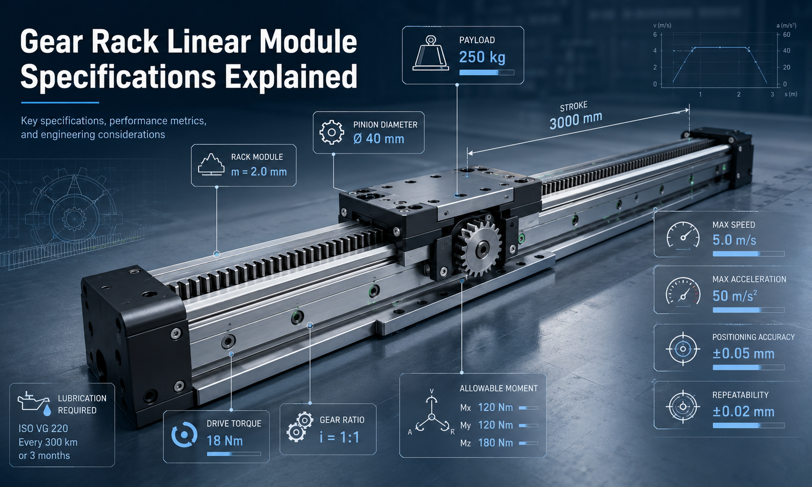
Key Gear Rack Linear Module Specifications
| Specification | What It Describes | Why It Matters |
|---|---|---|
| Payload | The maximum mass or force supported by the carriage | Determines whether the axis can carry the workpiece, tooling and moving equipment |
| Stroke | The available linear travel distance | Defines the working range of the linear axis |
| Rack Module | The standardized size of the rack and pinion teeth | Affects tooth strength, drive force, pinion size and transmission capacity |
| Pinion Diameter | The pitch diameter of the drive pinion | Influences linear travel per revolution, speed, torque and resolution |
| Gear Ratio | The speed reduction ratio between the motor and pinion | Balances output torque, speed and positioning resolution |
| Maximum Speed | The highest permitted linear operating speed | Determines whether the axis can meet cycle-time requirements |
| Acceleration | The rate at which the carriage changes speed | Affects inertial force, motor sizing, structural vibration and cycle time |
| Positioning Accuracy | The difference between the commanded position and actual position | Determines absolute motion accuracy across the complete stroke |
| Repeatability | The ability to return to the same position repeatedly | Important for repetitive automation, loading and assembly operations |
| Drive Torque | The torque required at the motor or pinion | Determines whether the drive can overcome load, friction and acceleration forces |
| Allowable Moment | The maximum roll, pitch and yaw moment supported by the carriage | Prevents guide overload when the load center is offset |
| Lubrication Requirements | The required lubricant, application method and maintenance interval | Affects tooth wear, noise, efficiency and service life |
Payload Capacity
Payload is the mass that the gear rack linear module can move while maintaining the specified speed, accuracy and service life. It normally includes more than the workpiece itself. The complete moving mass may include:
- Workpieces or products
- Fixtures and mounting plates
- Grippers, welding heads, cameras or dispensing equipment
- Motors and secondary axes mounted on the carriage
- Cable carriers, hoses and other moving accessories
The rated payload should not be treated as an isolated value. A module may support a large static load but require a lower operating load when it is subjected to high acceleration, frequent reversing, impact or an offset center of gravity.
Static Load and Dynamic Load
Static load refers to the load supported when the carriage is stationary or moving very slowly. Dynamic load includes the additional forces generated during acceleration, deceleration and direction changes.
The acceleration force can be estimated with:
Fa= m × a
Where:
Fais acceleration force in newtonsmis the total moving mass in kilogramsais acceleration in meters per second squared
For a horizontal axis, the total drive force may include acceleration force, friction, process force, cable drag and external resistance:
Ftotal= Fa+ Ffriction+ Fprocess+ Fexternal
For inclined or vertical installations, gravity must also be included. Vertical axes generally require a holding brake or another anti-fall mechanism to prevent uncontrolled movement when power is removed.
Use a Safety Factor
A suitable safety factor should be applied to account for load variation, vibration, shock, installation errors and future operating changes. The required safety factor depends on the duty cycle and application severity. Continuous industrial operation, high-impact motion and uncertain loads normally require a larger design margin than smooth, intermittent movement.
Stroke and Maximum Travel
Stroke is the usable distance that the carriage can travel. Rack and pinion systems are especially suitable for long-stroke automation because rack sections can be installed continuously along an aluminum profile or steel beam.
When determining the required stroke, consider:
- The actual process travel
- Acceleration and deceleration distance
- End clearance
- Limit switch and sensor positions
- Tool length and workpiece dimensions
- Maintenance and loading access
- Possible future expansion
The overall module length is always greater than the usable stroke because space is required for the carriage, end structures, protective components and overtravel protection.
Rack Joint Accuracy
Very long axes usually use multiple rack sections. The alignment of the joints affects motion smoothness, noise and positioning accuracy. Improper rack spacing at a joint can create a sudden change in tooth engagement, producing vibration, impact and local wear.
For long-stroke systems, the mounting surface must also maintain adequate straightness, flatness and rigidity. Extending the rack does not automatically guarantee that the complete axis will maintain the same accuracy over the entire travel.
Rack Module
Rack module is one of the most important rack and pinion actuator specifications. It defines the size of the gear teeth and is calculated from the relationship between the pinion pitch diameter and the number of teeth:
m = dp÷ z
Where:
mis the gear moduledpis the pinion pitch diameterzis the number of pinion teeth
A larger rack module generally provides larger and stronger teeth, allowing the transmission to support greater tangential force. However, increasing the module also increases the physical size, weight and cost of the rack and pinion assembly.
Rack module selection should consider:
- Required linear drive force
- Peak acceleration force
- Pinion torque
- Tooth material and heat treatment
- Gear face width
- Duty cycle
- Shock and vibration
- Expected service life
- Required accuracy and smoothness
The module alone does not define the complete load capacity. Two racks with the same module may have different allowable forces because of differences in material, hardness, tooth width, manufacturing quality and mounting method.
Spur Rack and Helical Rack
Spur racks use straight teeth and provide a simple, efficient and economical transmission structure. Helical racks engage more gradually and can provide smoother motion, lower noise and higher tooth contact ratios. However, helical gearing can generate additional axial force that must be supported by the bearing and guide structure.
Pinion Diameter
The pinion converts rotary motor motion into linear movement along the rack. Its pitch diameter directly affects linear travel per revolution, output force, maximum speed and positioning resolution.
The pitch diameter is:
dp= m × z
The theoretical linear travel for one pinion revolution is:
Lrev= π × dp
A larger pinion moves the carriage farther per revolution and can increase linear speed at the same rotational speed. However, a larger pitch diameter also requires more torque to produce the same linear force.
A smaller pinion provides less travel per revolution, which can improve mechanical resolution and reduce the required pinion torque. The pinion cannot be made arbitrarily small because tooth geometry, tooth strength, undercut risk and bearing dimensions must also be considered.
Gear Ratio
A gearbox is commonly installed between the servo motor and pinion. The gear ratio is normally expressed as:
i = nmotor÷ npinion
Where:
iis the reduction rationmotoris motor speednpinionis pinion speed
A higher reduction ratio lowers the pinion speed while increasing the available output torque. It can also improve command resolution because more motor revolutions are required for the same linear travel.
A lower reduction ratio allows higher linear speed but provides less torque multiplication. The selected ratio must keep the motor within its effective speed and torque range throughout acceleration, constant-speed travel and deceleration.
Gearbox selection should also consider:
- Rated and peak output torque
- Backlash
- Torsional rigidity
- Efficiency
- Maximum input speed
- Radial and axial load capacity
- Emergency-stop torque
- Service life
Maximum Speed
The theoretical linear speed of a gear rack actuator can be calculated from pinion speed and pitch diameter:
v = π × dp× npinion ÷ 60
Where:
vis linear speed in meters per seconddpis pinion pitch diameter in metersnpinionis pinion speed in revolutions per minute
The practical maximum speed may be lower than the theoretical result. It can be limited by:
- Motor maximum speed
- Gearbox input and output speed limits
- Guide system capacity
- Rack and pinion engagement quality
- Lubrication condition
- Carriage stability
- Structural vibration
- Cable carrier speed
- Noise requirements
- Controller and servo tuning
Long travel does not automatically mean unlimited operating speed. As the axis becomes longer, beam deflection, mounting accuracy, natural frequency and cable management become increasingly important.
Acceleration and Deceleration
Acceleration has a direct effect on cycle time, but it also increases the force and torque required from the transmission. High acceleration can generate significant dynamic loads even when the payload is relatively small.
The complete acceleration specification should include:
- Maximum acceleration
- Normal operating acceleration
- Maximum deceleration
- Emergency-stop deceleration
- Jerk or acceleration transition rate
- Number of cycles per minute
A smooth S-curve motion profile can reduce shock, vibration and tooth impact compared with an abrupt acceleration profile. Servo tuning should be matched to the mechanical rigidity of the axis rather than using the highest available gain settings.
Positioning Accuracy
Positioning accuracy describes how closely the actual carriage position matches the commanded position over the full stroke. It is an absolute performance specification and should not be confused with repeatability.
Gear rack linear module positioning accuracy can be affected by:
- Rack pitch error
- Rack joint alignment
- Gearbox backlash
- Rack and pinion backlash
- Pinion runout
- Guide straightness
- Base mounting accuracy
- Structural deflection
- Thermal expansion
- Encoder resolution
- Servo control error
For applications requiring high absolute accuracy over a long stroke, a linear encoder can be installed to measure the actual carriage position directly. This creates a full closed-loop system and can compensate for some transmission and pitch errors. However, it cannot correct insufficient rigidity, poor rack installation or excessive mechanical wear.
Repeatability
Repeatability describes the ability of the carriage to return to the same position under the same operating conditions. A system may have good repeatability even when a constant absolute positioning offset is present.
Repeatability is particularly important for:
- Pick-and-place operations
- Machine loading and unloading
- Welding
- Dispensing
- Packaging
- Assembly
- Inspection
- Material handling
Backlash, drive rigidity, load direction, temperature and servo tuning all influence repeatability. For bidirectional positioning, the specification should be evaluated when approaching the target from both directions, because reversing the drive can expose gearbox and tooth-clearance errors.
Drive Torque
Drive torque must be sufficient to produce the required linear force at the pinion. The relationship between tangential drive force and pinion torque is:
Tpinion= Ftotal× dp ÷ 2
Where:
Tpinionis torque at the pinionFtotalis the total required linear forcedpis the pinion pitch diameter
When a gearbox is used, the approximate motor torque requirement can be expressed as:
Tmotor= Ftotal× dp÷ (2 × i × h)
Where:
iis the gearbox reduction ratiooris the combined transmission efficiency
Motor selection must verify both continuous torque and peak torque. Continuous torque relates to thermal performance during repeated operation, while peak torque is required during acceleration, deceleration, reversing and emergency stopping.
The reflected inertia of the moving system should also be compared with the motor inertia. An unsuitable inertia ratio can make servo tuning difficult and lead to vibration, overshoot or slow settling.
Allowable Moment
Allowable moment specifies the maximum rotational load that the guide and carriage can support. It is usually divided into three directions:
- Roll moment:Rotation around the direction of travel
- Pitch moment:Forward or backward tilting of the carriage
- Yaw moment:Rotation in the horizontal plane
Moment load is generated when the payload center of gravity or process force is offset from the carriage center:
M = F × e
Where:
Mis the applied momentFis the applied forceeis the perpendicular offset distance
A relatively light payload can still overload the guide system when it is mounted far from the carriage. Therefore, payload and allowable moment must always be checked together.
Moment capacity can be improved by:
- Increasing the distance between guide blocks
- Using a wider carriage
- Using two parallel linear modules
- Adding an external support guide
- Reducing the load offset
- Increasing base rigidity
For multi-axis gantry systems, the weight and offset of the secondary axes must be included in the moment calculation of the supporting axis.
Lubrication Requirements
Correct lubrication reduces friction, tooth wear, noise and corrosion. It also helps maintain stable transmission efficiency and service life.
The lubrication specification should identify:
- Recommended grease or oil type
- Lubrication method
- Initial lubricant quantity
- Relubrication interval
- Operating temperature range
- Compatibility with the working environment
Lubrication intervals depend on operating speed, travel distance, load, duty cycle, contamination and ambient conditions. High-speed, continuous-duty or dusty applications may require more frequent lubrication than low-speed systems operating in clean environments.
Automatic lubrication systems are often suitable for long-stroke axes because they apply a controlled quantity of lubricant directly to the tooth surface. Protective covers, brushes or wipers can also reduce contamination from dust and machining debris.
Excessive lubricant should be avoided because it can attract contamination, increase resistance and spread into surrounding equipment. Lubricants should not be mixed unless their chemical compatibility has been confirmed.
How the Specifications Affect Each Other
Gear rack linear module specifications should not be selected independently. Changing one parameter usually affects several others.
| Design Change | Possible Benefit | Possible Trade-Off |
|---|---|---|
| Increase rack module | Higher tooth strength and drive-force capacity | Larger size, greater weight and potentially lower resolution |
| Increase pinion diameter | More linear travel per revolution and potentially higher speed | Higher torque required for the same linear force |
| Increase gearbox ratio | More output torque and improved command resolution | Lower maximum linear speed |
| Increase acceleration | Shorter cycle time | Higher force, torque, vibration and moment loads |
| Increase stroke | Larger working range | Greater sensitivity to alignment, beam deflection and thermal expansion |
| Increase payload | Ability to carry larger tooling or products | Higher motor torque, guide load and structural requirements |
Gear Rack Linear Module Selection Process
- Define the complete moving mass.Include the payload, fixture, carriage-mounted equipment, cable carrier and secondary axes.
- Determine the required stroke.Add process travel, safety clearance, acceleration distance and maintenance access.
- Define the motion profile.Specify maximum speed, acceleration, deceleration, travel time, dwell time and cycle frequency.
- Calculate the total drive force.Include inertia, friction, process force, gravity and external resistance.
- Select the rack module and pinion.Check tooth force, torque, service factor, duty cycle and expected life.
- Select the gearbox ratio.Balance motor speed, output torque and required linear resolution.
- Check guide load and allowable moments.Include the actual load center and forces from all mounted equipment.
- Verify accuracy and repeatability.Consider rack grade, joints, backlash, encoder configuration and mounting accuracy.
- Review structural rigidity.Check the support beam, mounting surface, carriage plate and machine frame.
- Define lubrication and protection.Select the lubrication method, protective covers and contamination-control measures.
- Apply an appropriate safety factor.Account for shock, uncertain loads, emergency stopping and long-term wear.
Common Specification Selection Mistakes
Checking Only Maximum Payload
Maximum payload does not show whether the module can withstand the actual acceleration, offset load, process force or operating cycle. Dynamic force and allowable moments must also be verified.
Ignoring the Load Center
A load mounted far from the carriage creates a large moment even when its mass is below the nominal payload rating. This can shorten guide life and reduce positioning stability.
Selecting Speed Without Checking Torque
A large pinion or low gearbox ratio may provide the required theoretical speed but leave insufficient torque for acceleration and process resistance.
Confusing Accuracy with Repeatability
Good repeatability does not guarantee good absolute positioning accuracy. Long-stroke applications may require rack-error compensation or direct linear feedback.
Ignoring Rack Joints
Poor alignment between rack sections can cause vibration, noise, tooth impact and local positioning errors.
Using Static Torque for Servo Selection
Motor selection must include peak acceleration torque, continuous RMS torque, reflected inertia and emergency-stop conditions.
Neglecting Lubrication and Contamination
An incorrectly lubricated rack may experience rapid tooth wear even when the mechanical sizing is otherwise correct.
Frequently Asked Questions
What determines the maximum load of a gear rack linear module?
The maximum load depends on the guide capacity, rack tooth strength, pinion torque, gearbox capacity, carriage structure, allowable moments, speed, acceleration and duty cycle. It cannot be determined from rack module alone.
How is rack module selected?
Rack module is selected according to the required tangential force, peak torque, tooth material, face width, duty cycle, shock load and service-life requirement. A larger module generally supports more force but also increases component size.
Does a larger pinion increase speed?
Yes. At the same pinion rotational speed, a larger pitch diameter produces more linear travel per revolution. However, it also requires more torque to generate the same linear force.
What is the difference between positioning accuracy and repeatability?
Positioning accuracy measures how close the actual position is to the commanded position. Repeatability measures how consistently the module returns to the same position during repeated cycles.
Can a gear rack linear module be used for unlimited stroke?
Rack sections can be joined to create very long travel distances, so the stroke is highly scalable. In practice, the total travel is limited by machine structure, rack alignment, cable management, control requirements and installation space.
Why is allowable moment important?
Allowable moment determines whether the guide and carriage can support offset loads. A payload below the maximum mass rating can still overload the module when its center of gravity is too far from the carriage.
How often should the rack be lubricated?
The lubrication interval depends on load, speed, travel distance, duty cycle, temperature and contamination. The lubricant and interval should follow the rack and module manufacturer’s maintenance requirements.
Conclusion
Correct gear rack linear module selection requires a combined evaluation of payload, stroke, rack module, pinion diameter, gear ratio, maximum speed, acceleration, positioning accuracy, repeatability, drive torque, allowable moment and lubrication requirements.
The best configuration is not simply the module with the highest load or speed rating. It is the configuration that provides sufficient dynamic force, structural rigidity, accuracy and service life under the actual operating cycle. Defining the complete motion profile and load conditions before selecting the rack, pinion, gearbox and motor helps prevent oversizing, insufficient torque, guide overload and premature wear.
