 English

Agear rack linear moduleis an industrial linear motion system that converts motor rotation into controlled linear movement through the meshing action of a pinion gear and a linear rack. It is commonly used in automation equipment requiring long travel distances, high load capacity, high transmission rigidity and continuous high-speed motion.
Unlike a ball screw linear module, which moves a nut along a rotating screw, a rack and pinion linear module uses a motor-driven pinion that rotates against a fixed or moving rack. As the pinion turns, the carriage or complete axis moves along a straight guide system. Because the rack can be manufactured and installed in multiple connected sections, this drive system is particularly suitable for long-stroke applications where screw length, critical speed and manufacturing limitations become important concerns.
Gear racklinear modulesare widely used ingantry robots, Cartesian systems, laser cutting machines, CNC equipment, automated production lines, material handling systems, welding systems, logistics equipment and other heavy-duty automation applications.
This article explains what a gear rack linear module is, how the rack and pinion drive works, its main structural components, performance characteristics, advantages, limitations and typical industrial applications.
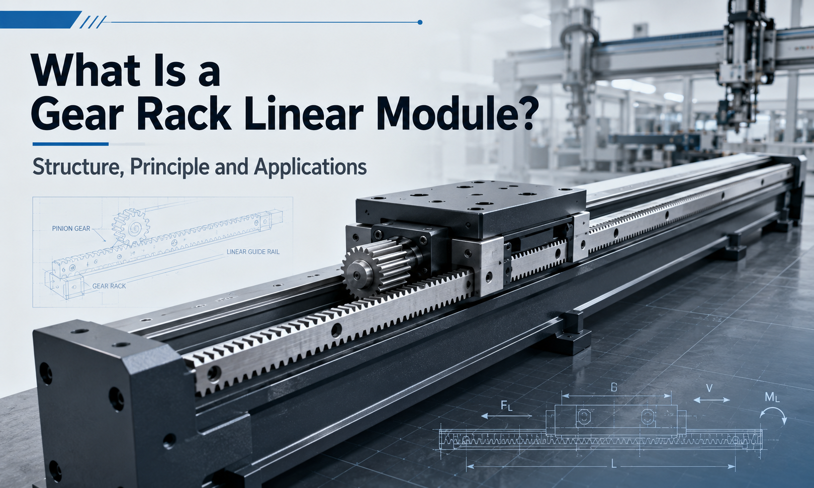
What Is a Gear Rack Linear Module?
A gear rack linear module, also called arack and pinion linear module, rack driven linear axisorgear rack actuator, is a modular linear motion unit that integrates a rack and pinion transmission, linear guide system, carriage, motor mounting structure, lubrication components, limit sensors and supporting frame.
The rack is a straight mechanical component with evenly distributed gear teeth along its length. The pinion is a circular gear that meshes with the rack. When the motor rotates the pinion, the rotational movement of the gear is converted into linear movement along the rack.
Depending on the mechanical design, the rack may remain fixed while the motor, gearbox, pinion and carriage move along the axis. In other configurations, the pinion assembly remains stationary while the rack and connected moving structure travel. The fixed-rack and moving-pinion arrangement is widely used because it avoids moving a long and heavy rack assembly.
The complete module is normally designed as a standardized axis that can be integrated into single-axis, XY, XZ, XYZ, dual-drive gantry and multi-axis automation systems.
How Does a Rack and Pinion Linear Module Work?
The working principle of a gear rack linear module is based on direct mechanical engagement between the pinion teeth and the rack teeth.
- The servo motor or stepper motor generates rotary motion.
- A gearbox, coupling or direct-drive connection transfers motor torque to the pinion shaft.
- The pinion rotates and engages with the teeth of the rack.
- The meshing force between the pinion and rack produces linear thrust.
- The carriage moves along one or more linear guide rails.
- Themotion controllerregulates position, speed and acceleration.
- Limit switches, home sensors or encoders provide position and safety feedback.
The linear travel generated by each revolution of the pinion depends mainly on the pitch diameter of the pinion. A larger pinion generally produces more linear travel per revolution, while a smaller pinion can provide greater mechanical force for the same drive torque.
In servo-driven systems, the motor encoder continuously reports the motor position to the controller. The controller compares the commanded position with the actual position and adjusts motor output accordingly. This closed-loop control enables the rack driven linear axis to perform accurate positioning, synchronized multi-axis movement and repeated production cycles.
Basic Structure of a Gear Rack Linear Module
A gear rack linear module is not simply a rack and a gear. It is a complete mechanical and motion-control assembly designed to support loads, guide movement and maintain stable gear engagement.
1. Supporting Base or Structural Beam
The supporting base provides the main mechanical foundation of the linear axis. Depending on the required stroke, payload and rigidity, it may be manufactured from aluminum extrusion, welded steel, machined steel or a reinforced structural beam.
Aluminum profiles are suitable for moderate loads and applications that require a lighter modular structure. Steel beams are generally preferred for long-span, heavy-load and high-rigidity systems.
The straightness, flatness and torsional rigidity of the supporting structure directly affect the positioning accuracy and operating stability of the complete module.
2. Gear Rack
The rack is the main linear transmission component. It contains a series of straight or helical teeth along its length and is mounted parallel to the direction of movement.
Racks can be produced in multiple accuracy grades, tooth profiles, modules, materials and heat-treatment conditions. Hardened and ground racks are commonly used when the system requires high positioning accuracy, wear resistance and long operating life.
For long-stroke applications, multiple rack sections can be aligned and connected along the machine frame. Correct alignment of the joints is essential because tooth pitch errors or height differences between adjacent sections can produce impact, vibration, noise and positioning errors.
3. Pinion Gear
The pinion is the rotating gear that meshes with the rack. It receives torque from the motor or gearbox and generates linear driving force.
Pinion design parameters include tooth module, number of teeth, pitch diameter, pressure angle, tooth width, material and hardness. The pinion must match the rack profile precisely to achieve smooth transmission and avoid abnormal wear.
Because the pinion usually completes many more engagement cycles than an individual rack tooth, pinion material, hardness and lubrication conditions are especially important for service life.
4. Motor and Gearbox
Servo motors are commonly used in rack and pinion linear modules because they provide high speed, strong acceleration capability, closed-loop control and accurate synchronization. Stepper motors may be suitable for lower-speed or cost-sensitive applications with moderate positioning requirements.
A planetary gearbox is often installed between the motor and pinion. The gearbox can increase output torque, reduce motor speed and improve load-driving capability. However, gearbox backlash must be considered when calculating the total positioning error of the axis.
The motor and gearbox must be selected according to payload, friction, acceleration, operating speed, transmission efficiency, external force, duty cycle and safety factor.
5. Linear Guide System
The rack and pinion transmission generates motion, but it does not provide accurate linear guidance by itself. Linear guide rails and guide blocks are therefore installed to support the moving carriage and control its direction.
The guide system carries vertical loads, lateral loads and overturning moments. Heavy-duty rack modules may use two parallel guide rails with multiple guide blocks to improve rigidity and load distribution.
Rail spacing, block spacing, mounting accuracy and lubrication condition all influence the allowable load moment and operating stability of the axis.
6. Moving Carriage
The carriage is the moving platform that connects the rack and pinion drive to the external load. The motor, gearbox and pinion may be mounted directly on the carriage, depending on the module structure.
The carriage usually contains threaded mounting holes or positioning surfaces for installing robotic arms, grippers, fixtures, welding heads, cutting heads, inspection cameras or other automation components.
A well-designed carriage must provide sufficient rigidity without adding unnecessary moving mass. Excessive moving mass increases motor torque requirements and reduces acceleration performance.
7. Backlash Adjustment Mechanism
Clearance between the rack and pinion teeth is necessary to prevent binding, but excessive clearance creates backlash. Backlash can reduce positioning accuracy and cause impact during direction reversal.
Common methods for reducing backlash include:
- Adjusting the pinion installation distance
- Using spring-loaded or eccentric pinion mounting structures
- Using split pinions with preload
- Using dual-pinion preload systems
- Applying electronic compensation through the motion controller
For high-precision systems, mechanical preload is often more effective than relying only on software compensation.
8. Lubrication System
Correct lubrication reduces friction, tooth surface wear, temperature rise and operating noise. Grease or oil may be applied manually, through an automatic lubrication unit or through a lubrication pinion.
Long-stroke and high-duty-cycle equipment often benefits from centralized automatic lubrication because it provides more consistent lubricant distribution and reduces maintenance dependence on operators.
9. Sensors and Limit Switches
Home sensors establish the machine reference position, while limit switches prevent the carriage from traveling beyond the safe operating range. Additional sensors may be used for position confirmation, collision detection or maintenance monitoring.
Mechanical end stops are also commonly installed as a secondary safety measure. They should not be used as normal positioning devices because repeated impact can damage the module.
10. Protective Components
Depending on the operating environment, the module may include bellows, metal covers, cable carriers, dust shields, rack covers or sealing components.
Protection is particularly important in environments containing metal chips, welding spatter, abrasive dust, coolant, oil mist or other contaminants that could enter the rack teeth or linear guide system.
Straight Rack and Helical Rack Designs
Gear rack linear modules may use either straight-tooth racks or helical-tooth racks.
Straight-Tooth Rack
A straight rack has teeth perpendicular to the direction of travel. It has a simple structure, is relatively economical and is suitable for many general industrial applications.
However, straight teeth engage more suddenly than helical teeth. At high speeds, this can result in greater transmission noise and vibration.
Helical Rack
A helical rack has angled teeth that engage progressively. Several teeth can remain partially engaged at the same time, improving contact continuity and load distribution.
Helical rack systems generally offer smoother motion, lower noise, higher load capacity and improved transmission precision. They are often used in high-speed machine tools, laser processing equipment and precision gantry systems.
Because helical tooth engagement generates axial force, the bearing and mounting structure must be designed to resist the additional force.
Why Gear Rack Linear Modules Are Suitable for Long Stroke Motion
Long-stroke capability is one of the most important advantages of a gear rack linear module.
A ball screw becomes more difficult to use as the stroke increases. Long screws are more susceptible to bending, vibration and critical-speed limitations. Manufacturing, transporting and installing a very long precision screw can also be challenging.
A rack does not rotate along its full length. It can be divided into multiple sections and mounted continuously on a long machine frame. The pinion travels along the rack, allowing the system to achieve long travel without rotating a long shaft.
This modular construction makes rack and pinion drives suitable for:
- Large gantry robots
- Long production lines
- Laser cutting and plasma cutting machines
- Large-format CNC equipment
- Warehouse transfer systems
- Automated loading and unloading equipment
- Heavy-duty material handling systems
In practical engineering, the achievable stroke is determined mainly by the machine frame, rack installation length, guide rail arrangement, cable management and site space rather than by the length of a rotating transmission shaft.
Heavy Load Capability
Gear rack linear modules are often selected for heavy-load applications because the transmission force is transferred through direct tooth engagement. The rack can be mounted on a rigid steel structure, while large guide rails and multiple guide blocks support the payload.
Heavy-load capability depends on several factors:
- Motor output torque
- Gearbox reduction ratio
- Pinion pitch diameter
- Rack tooth size and material
- Tooth surface hardness
- Number and size of guide blocks
- Distance between guide rails
- Carriage rigidity
- Machine frame rigidity
- Acceleration and deceleration requirements
- Load center position
Payload alone is not enough to determine whether a module is suitable. Engineers must also calculate radial forces, axial forces and overturning moments caused by an offset load.
A relatively light load located far from the carriage center can create a larger moment than a heavier load mounted close to the carriage. For this reason, the installation position and center of gravity must be included in the selection process.
Performance Characteristics of Gear Rack Linear Modules
Long Travel Range
Rack sections can be connected to support long motion distances. This makes the design suitable for large machines and production lines where conventional screw-driven axes may be impractical.
High Speed
Because there is no long rotating screw, rack driven axes are not affected by screw critical-speed limitations in the same way as ball screw systems. They can therefore support high linear speeds over long travel distances when the motor, gearbox, guides and frame are correctly designed.
High Acceleration
Servo-driven rack modules can provide rapid acceleration and deceleration. The actual acceleration depends on moving mass, motor torque, gearbox ratio, frame rigidity and control settings.
Strong Load Capacity
Large tooth profiles, hardened racks, high-torque gearboxes and heavy-duty guide systems allow the module to move substantial loads.
High Structural Rigidity
When installed on a rigid steel beam with wide rail spacing, the module can resist vibration and load moments effectively.
Flexible Stroke Expansion
The travel range can be extended by adding rack and guide sections, provided that the supporting structure and alignment accuracy are maintained.
Suitable for Multi-Axis Systems
Gear rack modules can be combined into XY, XZ, XYZ and gantry configurations. Two parallel rack axes can also be electronically synchronized to drive a wide crossbeam.
Backlash Must Be Controlled
Rack and pinion systems normally have some mechanical clearance. High-precision applications require preload, precision gearboxes, suitable tooth accuracy and effective control compensation.
Installation Accuracy Is Important
Long racks and guide rails must be installed with accurate parallelism, straightness and joint alignment. Installation errors can cause uneven tooth contact, excessive noise and premature wear.
Gear Rack Linear Module Accuracy
The accuracy of a gear rack linear module depends on the complete transmission and guidance system rather than on the rack alone.
Main accuracy factors include:
- Rack pitch accuracy
- Pinion machining accuracy
- Gearbox backlash
- Rack and pinion engagement clearance
- Guide rail straightness
- Frame deformation
- Rack section joint alignment
- Motor encoder resolution
- Controller interpolation accuracy
- Thermal expansion
- Load-induced deformation
Positioning accuracy describes how close the actual position is to the commanded position. Repeatability describes how consistently the axis returns to the same position under the same operating conditions.
A rack driven system may have very good repeatability even when its absolute positioning accuracy requires calibration or compensation. Linear encoders can be added when the application needs direct measurement of the carriage position rather than relying only on the motor encoder.
Common Applications of Gear Rack Linear Modules
Gantry Robots
Gear rack linear modules are widely used as the horizontal axis of large gantry robots. Their long-stroke capability and heavy-load performance make them suitable for moving crossbeams, robotic arms, grippers and workpieces across large working areas.
Cartesian Robot Systems
Rack driven axes can be combined with ball screw, timing belt or additional rack axes to build XY, XZ and XYZ Cartesian robots. These systems are used for loading, unloading, palletizing, transfer and assembly.
Laser Cutting Machines
High-speed laser cutting machines often use precision helical rack drives because they require long travel, rapid acceleration, smooth movement and stable transmission.
CNC Machine Tools
Large-format routers, milling machines and machining systems may use rack and pinion drives when the required stroke is too long for a practical ball screw arrangement.
Welding Automation
Rack driven modules can move welding torches, positioners and robotic equipment along long workpieces. Protective covers and suitable lubrication are important because welding environments may contain spatter and dust.
Material Handling
Heavy-duty rack axes are used for transporting components, fixtures, pallets, battery modules, metal parts and production materials between workstations.
Automated Loading and Unloading
Long-stroke rack modules can move robotic grippers between machine tools, storage positions and conveyor lines. They are commonly used in automated manufacturing cells.
Logistics and Warehousing
Rack driven systems are used in transfer units, storage equipment, stacking systems and other warehouse automation systems requiring long horizontal movement.
Large Inspection Systems
Vision cameras, laser scanners and measurement sensors can be moved over large products using a rack driven linear axis.
New Energy Production Equipment
Gear rack modules can be used in battery, solar and energy-storage production lines for material transfer, stacking, handling and long-distance positioning.
Gear Rack vs Ball Screw Linear Module
| Comparison Item | Gear Rack Linear Module | Ball Screw Linear Module |
|---|---|---|
| Typical Stroke | Suitable for long and very long travel | More suitable for short and medium travel |
| Maximum Speed | Well suited to high speed over long distances | May be limited by screw critical speed |
| Load Capacity | Suitable for heavy loads and large structures | Suitable for precision loads within screw capacity |
| Positioning Accuracy | Depends heavily on rack grade, backlash and installation | Generally easier to achieve high positioning accuracy |
| Backlash | Requires preload or compensation | Can use preloaded ball nuts |
| Stroke Expansion | Can be extended with multiple rack sections | Limited by screw manufacturing and operating length |
| Typical Applications | Gantry robots, laser cutting, long production lines | Precision assembly, inspection and machine positioning |
The correct choice depends on the required stroke, speed, load, accuracy, installation space and budget. A gear rack linear module is generally preferred for long-stroke, high-speed and heavy-duty movement, while aball screw moduleis often preferred when compact size and high positioning accuracy are more important.
Gear Rack vs Timing Belt Linear Module
| Comparison Item | Gear Rack Linear Module | Timing Belt Linear Module |
|---|---|---|
| Load Capability | Better suited to heavy loads | Better suited to light and medium loads |
| Structural Rigidity | High when mounted on a rigid frame | Lower because of belt elasticity |
| Long Stroke | Excellent for very long travel | Suitable for long travel within belt design limits |
| Maintenance | Requires tooth lubrication and engagement inspection | Requires belt tension and wear inspection |
| Noise | Can be higher, especially with straight teeth | Generally quieter |
| Typical Use | Heavy-duty gantries and large machines | High-speed transfer and lightweight automation |
Advantages of Gear Rack Linear Modules
- Suitable for long and very long travel distances
- Strong load and thrust capacity
- High speed over long strokes
- Good compatibility with large gantry structures
- Flexible modular stroke extension
- No long rotating screw critical-speed limitation
- Suitable for harsh and heavy-duty industrial applications
- Can be combined into multi-axis automation systems
- Supports dual-drive synchronized gantry configurations
- Available with straight or helical rack designs
Limitations of Gear Rack Linear Modules
- Backlash must be controlled for precision positioning
- Rack and guide installation requires accurate alignment
- Gear teeth require regular lubrication
- Open rack structures can be affected by dust and debris
- Operating noise may be higher than a belt-driven system
- Long machine frames require sufficient structural rigidity
- Rack section joints must be installed carefully
- High-precision systems may require linear encoder feedback
How to Select a Gear Rack Linear Module
Selecting the correct gear rack linear module requires a complete evaluation of the mechanical load, motion profile and operating environment.
1. Determine the Required Stroke
Define the effective travel distance and include additional space for acceleration, deceleration, sensor positions, mechanical stops and maintenance access.
2. Calculate the Payload and Load Moment
Consider the total moving mass, including the workpiece, fixture, gripper, motor cables and carriage-mounted equipment. Calculate overturning moments according to the load center position.
3. Define Speed and Acceleration
Maximum speed alone is not sufficient. Acceleration, deceleration, cycle time and movement frequency determine the actual motor torque and structural load.
4. Establish Accuracy Requirements
Specify positioning accuracy, repeatability, resolution and allowable backlash separately. Do not use these terms as if they describe the same performance.
5. Select the Rack Type
Straight racks are suitable for general applications, while helical racks are often selected for smoother, quieter and higher-performance movement.
6. Select the Motor and Gearbox
The drive system should provide sufficient continuous torque, peak torque and speed while maintaining an appropriate safety margin.
7. Check the Supporting Frame
A high-quality rack module cannot perform accurately on a flexible or poorly aligned frame. The base structure must provide adequate straightness, flatness and torsional rigidity.
8. Evaluate the Environment
Dust, chips, coolant, temperature, humidity, cleanroom requirements and corrosion risk affect material selection, lubrication and protective design.
9. Consider Cable Management
Long-stroke systems require correctly sized cable carriers and flexible cables. The carrier bending radius, travel length and installation direction must be considered.
10. Plan Maintenance Access
The machine design should allow technicians to inspect rack teeth, replenish lubricant, adjust pinion engagement and replace wear components safely.
Installation Requirements
Correct installation is essential for the performance and service life of a rack driven linear axis.
- Inspect the mounting surface for flatness and cleanliness.
- Align the guide rails before final tightening.
- Install rack sections parallel to the guide system.
- Use alignment tools at rack joints to maintain tooth pitch continuity.
- Adjust pinion engagement without excessive preload.
- Check carriage movement across the full stroke.
- Verify motor, gearbox and coupling alignment.
- Install home sensors, limit switches and mechanical stops.
- Apply the specified lubricant before operation.
- Perform low-speed commissioning before increasing speed and load.
For dual-drive gantry systems, both sides must be mechanically aligned and electronically synchronized. Incorrect synchronization can twist the crossbeam, overload the guide blocks and damage the rack teeth.
Maintenance of Gear Rack Linear Modules
Regular maintenance helps maintain positioning performance and prevent unexpected downtime.
- Inspect rack and pinion teeth for wear, pitting or damage.
- Maintain the specified lubrication interval.
- Check for abnormal noise and vibration.
- Inspect rack joints and mounting bolts.
- Check pinion backlash and engagement condition.
- Inspect gearbox output bearings and seals.
- Clean debris from the rack and guide system.
- Inspect cable carriers and flexible cables.
- Check home and limit sensor operation.
- Verify gantry synchronization when dual drives are used.
Maintenance intervals should be adjusted according to operating speed, travel distance, load, duty cycle, contamination level and lubricant type. Equipment operating continuously in dusty or high-load conditions generally requires more frequent inspection.
Frequently Asked Questions
Is a gear rack linear module suitable for precision positioning?
Yes. A precision rack, low-backlash gearbox, preloaded pinion system, rigid frame and suitable feedback system can provide accurate positioning. For very high absolute accuracy, a linear encoder may be added to measure the carriage position directly.
How long can a gear rack linear module travel?
The rack can be installed in connected sections, so the stroke can be extended according to the machine structure and application requirements. Practical limits are usually related to frame rigidity, guide installation, cable management and available space.
Can a gear rack module carry heavy loads?
Yes. Rack and pinion systems are widely used in heavy-duty automation. Actual load capacity depends on motor torque, gearbox ratio, rack size, guide system, carriage design and load moment.
Does a rack and pinion drive have backlash?
Some clearance normally exists between the teeth. Backlash can be reduced using preload mechanisms, dual pinions, precision gearboxes and controller compensation.
Should I choose a straight rack or a helical rack?
A straight rack is economical and suitable for many general applications. A helical rack is usually preferred when smoother movement, lower noise, higher load capacity or improved transmission precision is required.
Can two gear rack modules be synchronized?
Yes. Two rack driven axes are often installed on opposite sides of a gantry and synchronized electronically through the motion controller. Correct mechanical alignment and servo tuning are essential.
Conclusion
Agear rack linear moduleis a powerful linear motion solution for industrial equipment requiring long travel, heavy load capacity, high speed and strong structural rigidity. Its rack and pinion transmission converts motor rotation into direct linear motion while allowing the travel range to be extended through modular rack sections.
The complete system normally includes a rack, pinion, motor, gearbox, linear guides, carriage, supporting frame, lubrication system, sensors and protective components. Each component affects the load capacity, accuracy, speed, noise, service life and maintenance requirements of the axis.
Compared with ball screw andtiming belt modules, rack driven linear axes are especially suitable for large gantry robots, laser cutting machines, CNC equipment, material handling systems, logistics automation and other long-stroke heavy-duty applications.
Successful selection requires more than checking payload and stroke. Engineers must also evaluate speed, acceleration, load moment, backlash, rack accuracy, guide arrangement, frame rigidity, environmental conditions and maintenance requirements. When properly designed, installed and maintained, a gear rack linear module can provide stable and efficient motion for demanding industrial automation systems.
