 English

Gear rack linear modules are widely used in long-stroke automation systems because they provide high speed, strong load capacity and scalable travel. Typical applications includegantry robots, material handling equipment, laser cutting systems, welding automation and large-format production machinery.
Although rack-and-pinion drives are durable, their performance depends on regular inspection, cleaning, lubrication and adjustment. Dust accumulation, insufficient lubrication, loose fasteners or increasing gear backlash can reduce positioning accuracy and eventually damage the rack, pinion, gearbox or linear guide.
This guide explains how to maintain a gear racklinear modulethrough daily inspections, rack cleaning, pinion checks, gearbox maintenance, guide rail servicing, lubrication, backlash monitoring and preventive maintenance planning.
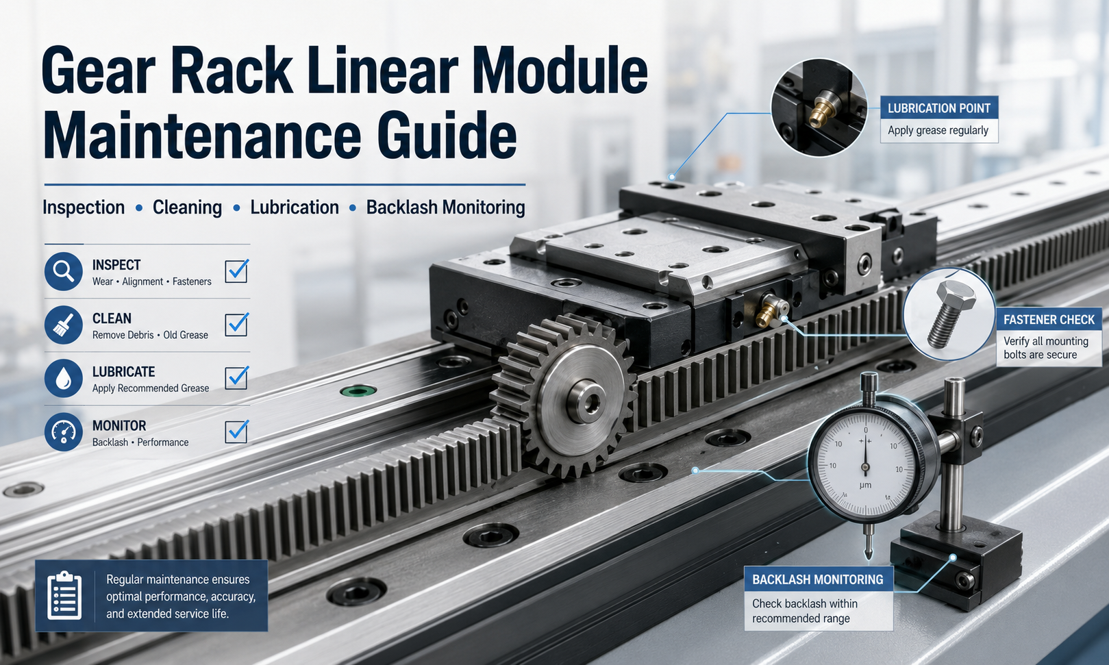
Why Gear Rack Linear Module Maintenance Is Important
A gear rack module transfers rotary motor motion into linear movement through the engagement between a pinion and a straight rack. During operation, the tooth surfaces repeatedly contact under load. The guide rails, bearings, gearbox and mounting components must also withstand acceleration, deceleration, vibration and external forces.
Proper maintenance helps:
- Maintain positioning accuracy and repeatability
- Prevent excessive rack-and-pinion wear
- Reduce abnormal noise and vibration
- Protect the gearbox, bearings and guide rails
- Detect increasing backlash before it affects production
- Reduce unexpected machine downtime
- Extend the service life of the complete linear axis
Maintenance frequency should be adjusted according to operating speed, load, duty cycle, installation orientation and environmental contamination.
Daily Inspection
A short visual and operational inspection should be performed before starting the equipment or at the beginning of each production shift.
Check the following conditions:
- Abnormal noise during acceleration, constant-speed travel or deceleration
- Unusual vibration from the carriage, gearbox or motor
- Metal particles, dust, oil contamination or foreign objects on the rack
- Loose mounting bolts, motor bolts or gearbox fasteners
- Damaged cables, cable carriers or sensor wiring
- Lubricant leakage around the gearbox or lubrication points
- Irregular movement, hesitation or sudden resistance
- Abnormal positioning errors or repeated servo alarms
The module should move smoothly throughout its full stroke. Any new noise, vibration or motion irregularity should be investigated before continuous operation.
Rack Cleaning
The rack tooth surface is exposed in many long-stroke linear systems. Dust, metal chips, welding residue and other contaminants can enter the tooth engagement area and cause tooth surface wear, pitting or unstable meshing.
Before cleaning, stop the machine, disconnect the power supply and prevent accidental axis movement. Remove large particles with a soft brush or industrial vacuum. Wipe the rack with a clean, lint-free cloth.
Do not use sharp metal tools to scrape the tooth surface. These tools may damage the tooth profile or leave scratches that accelerate wear.
After cleaning, inspect the entire rack length for:
- Damaged or deformed teeth
- Pitting or scoring on tooth surfaces
- Rust or discoloration
- Uneven contact marks
- Loose rack segments
- Misaligned joints between rack sections
In segmented rack systems, the connection between two rack sections deserves special attention. Incorrect joint spacing or height differences can create impact, noise and positioning errors when the pinion crosses the joint.
Pinion Inspection
The pinion should be inspected together with the rack because both components form one meshing system. Wear on one component can quickly affect the other.
Rotate or move the axis slowly and examine the accessible pinion teeth. Look for:
- Uneven tooth wear
- Cracks, dents or broken tooth edges
- Pitting on the contact surface
- Metal powder around the meshing area
- Excessive axial or radial movement
- Loose pinion mounting or locking components
A worn pinion may produce rhythmic noise that changes according to rotational speed. If the pinion is loose on the gearbox output shaft, the system may also develop inconsistent backlash and unstable positioning.
When severe wear is found, replacing only one damaged part may not restore correct meshing. The rack condition, pinion condition, alignment and backlash setting should be evaluated together.
Gearbox Check
Many gear rack linear modules use a planetary or right-angle gearbox to increase output torque and match the required motion speed. Gearbox condition directly affects axis accuracy, rigidity and drive stability.
During inspection, check for:
- Abnormal gearbox noise
- Excessive housing temperature
- Oil or grease leakage
- Loose mounting bolts
- Output shaft play
- Unexpected changes in rotational resistance
A moderate temperature increase may be normal during continuous operation. However, rapidly rising temperature, burnt lubricant odor or obvious vibration can indicate overloading, bearing damage, insufficient lubrication or internal gearbox wear.
Follow the gearbox manufacturer’s lubrication and replacement requirements. A sealed, lifetime-lubricated gearbox should not be opened unless servicing is performed by qualified personnel.
Guide Rail Maintenance
The rack-and-pinion mechanism generates the driving force, while the linear guide supports the carriage and controls straight-line motion. Poor guide rail maintenance can cause vibration, increased motor load and reduced positioning accuracy even when the rack drive remains in good condition.
Clean the guide rail surfaces and inspect them for contamination, rust, scratches or inadequate lubrication. Check the guide blocks for abnormal noise or looseness.
For systems with centralized lubrication, confirm that lubricant reaches every guide block. A blocked lubrication tube may leave one block dry while the remaining blocks continue to receive grease.
Do not mix incompatible lubricant types. Mixing different grease formulations can change viscosity, reduce lubrication performance or cause hard deposits inside the guide block.
Rack, Pinion and Guide Lubrication
Correct lubrication reduces friction, protects tooth surfaces and limits corrosion. The appropriate lubricant depends on speed, load, temperature, environmental conditions and the manufacturer’s specifications.
Before applying new lubricant, remove old grease and contaminants from the accessible rack surfaces. Apply a thin, even layer to the working tooth surfaces. Excessive grease can attract dust and metal particles, creating an abrasive paste that accelerates wear.
During lubrication:
- Use the specified grease or oil type
- Clean the lubrication tool before use
- Apply lubricant evenly across the operating stroke
- Move the axis slowly to distribute lubricant
- Remove excessive grease from exposed surfaces
- Record the lubrication date and lubricant type
High-speed, high-load or continuously operating equipment normally requires more frequent lubrication. Systems exposed to dust, coolant, moisture or welding particles may also need shorter service intervals.
Fastener Inspection
Repeated acceleration and deceleration can loosen rack mounting screws, guide rail bolts, carriage fasteners, gearbox bolts and motor mounting hardware.
Inspect all accessible fasteners according to the equipment maintenance schedule. Pay particular attention to:
- Rack mounting screws
- Rack locating blocks or alignment pins
- Guide rail mounting bolts
- Gearbox flange bolts
- Motor mounting bolts
- Pinion locking nuts or clamping elements
- Carriage and load mounting screws
- Sensor brackets and mechanical stops
Tighten bolts using the specified torque. Excessive tightening can deform components, damage threads or affect rack and guide alignment.
Backlash Monitoring
Backlash is the mechanical clearance between the rack and pinion teeth and within the gearbox. A controlled amount of clearance may be necessary for smooth movement, but excessive backlash reduces positioning accuracy and can create impact during direction reversal.
Possible signs of increasing backlash include:
- Positioning error after reversing direction
- Impact noise during acceleration or deceleration
- Visible movement before the carriage begins to travel
- Reduced repeatability
- Poor contour quality in cutting or machining applications
- Unstable synchronization in dual-drive gantry systems
Backlash can be measured using a dial indicator, laser measurement system or machine control feedback. Apply a small controlled force in opposite directions and record the displacement before the drive fully engages.
Compare measurement results with the original commissioning data. A gradual increase may indicate tooth wear, loose mounting, gearbox wear, bearing play or an incorrect pinion preload setting.
Do not eliminate backlash by forcing the pinion too tightly against the rack. Excessive preload increases friction, temperature, noise and tooth wear. Adjustment should follow the module design and manufacturer’s specified meshing clearance.
Sensor Inspection
Home sensors, limit sensors and position switches protect the equipment and provide reference positions for the control system. Contaminated or misaligned sensors can cause homing failures, overtravel alarms or unexpected stops.
Inspect:
- Sensor mounting position
- Trigger plate alignment
- Sensor-to-target distance
- Cable and connector condition
- Indicator light operation
- Home and limit signal response
After adjustment, move the axis at low speed and verify that each sensor changes state at the correct position. Confirm that the mechanical stop is not used as the normal travel limit.
Preventive Maintenance Schedule
| Maintenance Interval | Recommended Tasks |
|---|---|
| Daily or each shift | Check noise, vibration, motion smoothness, contamination, lubricant leakage, sensors and visible fasteners. |
| Weekly | Clean exposed rack surfaces, inspect cable carriers, check rack joints and examine pinion contact conditions. |
| Monthly | Inspect lubrication condition, guide rails, guide blocks, rack mounting screws, gearbox mounting and sensor alignment. |
| Every three to six months | Lubricate the rack and guide rails, check pinion wear, measure backlash and verify positioning repeatability. |
| Annually | Perform a complete mechanical inspection, check gearbox condition, verify alignment, inspect all fasteners and review maintenance records. |
These intervals are general recommendations. Heavy-duty, high-speed, high-cycle or contaminated applications may require significantly shorter inspection and lubrication periods.
Maintenance Requirements for Harsh Environments
Gear rack modules used in dusty, wet, corrosive or high-temperature environments require additional protection. Covers, bellows, automatic lubrication systems, air purging or corrosion-resistant treatments may be necessary.
In laser cutting, welding and machining environments, remove metal particles before they become embedded in lubricant. In humid locations, inspect exposed tooth surfaces for corrosion. For food, pharmaceutical or clean production environments, use approved lubricants and cleaning procedures appropriate for the application.
Common Maintenance Mistakes
- Applying new grease without removing contaminated old lubricant
- Using an incompatible or unspecified lubricant
- Ignoring small increases in noise or vibration
- Adjusting the pinion too tightly to eliminate backlash
- Replacing a worn pinion without checking rack condition
- Tightening rack screws without verifying alignment
- Operating the axis after repeated servo alarms
- Failing to record inspection and lubrication history
Maintenance records help identify gradual changes in backlash, temperature, noise and positioning performance. They also support more accurate planning for component replacement.
When Should Components Be Replaced?
Rack, pinion, gearbox or guide components should be repaired or replaced when inspection reveals severe pitting, broken teeth, excessive shaft play, repeated lubrication failure, abnormal heat or backlash that cannot be corrected through normal adjustment.
Before replacing parts, determine the cause of the damage. Incorrect alignment, overloading, insufficient lubrication or structural deformation can quickly damage a new component if the underlying problem is not corrected.
Conclusion
Effective gear rack linear module maintenance combines regular cleaning, correct lubrication, pinion and gearbox inspection, guide rail servicing, fastener checks, sensor verification and systematic backlash monitoring.
A preventive maintenance schedule should be based on the actual load, speed, operating hours and environmental conditions of the machine. Detecting contamination, looseness and wear at an early stage helps maintain positioning accuracy, reduce unexpected downtime and extend the service life of long-stroke rack-and-pinion linear systems.
