 English

Agear rack linear moduleis a mechanical linear motion system that converts motor rotation into controlled linear movement through the meshing of a pinion and a straight gear rack. It is commonly used in industrial automation applications that require long travel, high speed, heavy load capacity and continuous operation.
Unlike aball screw linear module, which transmits motion through a rotating screw and nut, a gear rack linear module uses a rotating pinion to drive a fixed or moving rack. This structure does not suffer from the same critical-speed limitations as long ball screws, making it particularly suitable for long-stroke axes,gantry robots, large processing machines, material handling equipment and automated production lines.
The performance of the system depends not only on the rack and pinion but also on the design of the base frame, linear guide, gearbox, carriage, motor mount, lubrication system, sensors, protective cover and cable management components. This article explains the completegear rack linear module structureand how each mechanical component contributes to load capacity, positioning performance and service life.
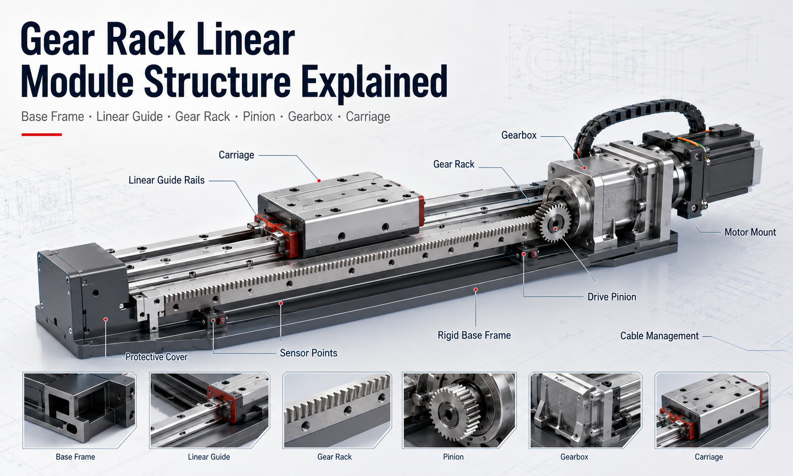
Basic Structure of a Gear Rack Linear Module
A typical gear rack linear module consists of a rigid supporting base, one or more linear guide rails, a precision gear rack, a drive pinion, a gearbox, a motor, a moving carriage and supporting protection or lubrication components.
During operation, the motor generates rotary motion. The gearbox adjusts the motor speed and increases the available torque before transmitting rotation to the pinion. As the pinion meshes with the rack, rotational motion is converted into linear movement. The carriage moves along the guide rails while carrying the workpiece, tooling or another automation axis.
The main structural components include:
- Base frame or supporting profile
- Linear guide rails and guide blocks
- Precision gear rack
- Drive pinion
- Planetary or helical gearbox
- Moving carriage
- Motor and motor mounting structure
- Pinion adjustment and preload mechanism
- Lubrication system
- Position and limit sensors
- Protective covers
- Cable chains and cable management components
These components must be designed as an integrated mechanical system. A high-quality rack alone cannot guarantee good motion performance if the base lacks rigidity, the guide rails are misaligned or the pinion is not correctly adjusted.
Base Frame and Supporting Structure
The base frame forms the primary load-bearing foundation of the gear rack linear module. It supports the guide rails, gear rack, carriage and drive components while maintaining the alignment of the entire motion axis.
Depending on the required load and travel length, the base may be manufactured from an aluminum extrusion, welded steel frame, machined steel beam or reinforced structural profile.
Aluminum Profile Base
Aluminum profiles are often used for medium-load automation systems because they provide a good balance between rigidity, weight, manufacturing cost and installation convenience. Extruded profiles may include mounting grooves, internal reinforcement ribs and integrated spaces for sensors or cable routing.
Aluminum bases are suitable for packaging machinery, assembly systems, inspection equipment and general material transfer applications. However, profile size and wall thickness must be selected according to the span, load and installation orientation.
Steel Base Frame
Steel structures are preferred for heavy-load, high-rigidity or very long-stroke applications. A welded and machined steel beam provides greater resistance to bending and torsional deformation, especially when the module carries large workpieces or operates as a gantry axis.
After welding, the steel structure may require stress relief and precision machining to provide accurate mounting surfaces for the guide rails and gear rack. Without proper processing, residual welding stress can cause gradual deformation and affect positioning accuracy.
Base Rigidity and Straightness
The base must remain straight under both static and dynamic loads. Excessive bending can change the engagement depth between the pinion and rack, increase guide block loading and introduce positioning errors.
For long axes, engineers must evaluate:
- Vertical deflection under payload
- Torsional deformation caused by offset loads
- Support spacing
- Mounting surface flatness
- Thermal expansion
- Natural frequency and vibration response
A well-designed base provides a stable reference for all other components and is essential for reliable long-term operation.
Linear Guide System
The gear rack transmits driving force, but it does not guide the carriage by itself. The carriage is supported and constrained by thelinear guide system, which normally consists of precision guide rails and recirculating ball guide blocks.
The guide rails control the direction of movement and resist forces in vertical, horizontal and moment directions. They also prevent the pinion from carrying loads that should be supported by the guide system.
Guide Rail Arrangement
Many gear racklinear modulesuse two parallel guide rails with two or more guide blocks on each rail. This arrangement provides high rigidity and resistance to pitch, yaw and roll moments.
Smaller systems may use a single wide guide rail, while heavy-duty systems may use larger rails or additional guide blocks. The required arrangement depends on the payload, carriage length, center-of-gravity position and external force direction.
Guide Rail Installation Accuracy
The guide rails must be mounted parallel to each other and aligned with the gear rack. If the rails are not parallel, the guide blocks may experience internal stress, abnormal friction and accelerated wear.
Incorrect alignment can also cause variation in rack-and-pinion engagement. The pinion may become too tight in one section and too loose in another, producing noise, vibration and inconsistent backlash.
Precision mounting surfaces, reference shoulders, alignment tools and controlled tightening sequences are normally used during assembly.
Guide Block Preload
Guide blocks may be supplied with different preload levels. Moderate preload improves rigidity and reduces clearance, but excessive preload increases friction and motor load.
The preload should be selected based on positioning accuracy, load, speed and operating environment. High-speed axes often require a balance between stiffness and low running resistance.
Gear Rack Structure
The gear rack is a straight mechanical component with evenly spaced teeth along its length. It acts as the linear counterpart of the rotating pinion and is one of the most important components in therack driven linear axis construction.
Straight Rack and Helical Rack
Gear racks are commonly available with straight teeth or helical teeth.
A straight rack has teeth positioned perpendicular to the direction of motion. It has a relatively simple structure, is easy to manufacture and is suitable for many standard industrial applications.
A helical rack uses angled teeth. Multiple teeth can share the load during meshing, which generally produces smoother motion, lower noise and higher load capacity. Helical racks are frequently used in high-speed machining equipment, precision gantry systems and demanding automation axes.
However, a helical gear set generates axial force, so the gearbox bearings and mounting structure must be able to resist the additional load.
Rack Module and Tooth Size
The module defines the size of the gear teeth. A larger module provides larger and stronger teeth, making it suitable for higher driving force and heavier loads. A smaller module allows smoother engagement and potentially finer motion resolution but has lower tooth strength.
The selected rack module must match the pinion module exactly. Tooth profile, pressure angle and helix angle must also be compatible.
Rack Accuracy Grade
Gear racks are manufactured in different accuracy grades. Higher-accuracy racks provide better tooth pitch consistency and reduced transmission error, but they also require more accurate installation and higher manufacturing cost.
Rack accuracy influences:
- Positioning accuracy
- Motion smoothness
- Transmission noise
- Speed stability
- Repeatability over long travel
The appropriate accuracy grade should be selected according to the actual application rather than automatically choosing the highest available grade.
Segmented Rack Assembly
For long travel lengths, the rack is normally assembled from multiple segments. Each segment is mounted end to end along the base.
The connection between adjacent rack sections must maintain the correct tooth pitch. If the joint is too narrow or too wide, the pinion can experience impact, noise and vibration when crossing the connection.
A matching rack piece, alignment gauge or dedicated installation tool may be used to set the tooth spacing at each joint. The mounting bolts should then be tightened in the specified sequence.
Drive Pinion
The pinion is the rotating gear that meshes with the rack. It receives torque from the gearbox output shaft and generates the linear driving force required to move the carriage.
Pinion Diameter and Tooth Count
The pinion diameter affects linear speed, output force and motion resolution. A larger pinion moves the carriage farther with each motor revolution and can produce higher linear speed. However, it requires more torque to generate the same linear force.
A smaller pinion provides greater mechanical advantage and finer displacement per revolution, but its maximum speed may be limited by tooth engagement frequency and gearbox speed.
Pinion Material and Heat Treatment
Industrial pinions are commonly made from alloy steel and may be hardened, ground or surface treated to improve wear resistance. The pinion material and hardness should be compatible with the rack.
Improper hardness matching can cause one component to wear significantly faster than the other. In many systems, the pinion is designed as a replaceable wear component because it rotates continuously and engages the rack over the full travel.
Pinion Mounting
The pinion may be mounted directly on the gearbox output shaft or through a separate bearing-supported shaft. Direct mounting produces a compact structure, while an independent shaft can provide additional support for high radial loads.
The mounting connection must prevent rotational looseness. Keyways, splines, locking assemblies, taper bushes or clamping hubs may be used depending on torque and service requirements.
Gearbox Structure
A gearbox is usually installed between the servo motor and pinion. Its main purpose is to reduce motor speed, increase output torque and improve the effective motion resolution of the system.
Planetary gearboxes are commonly used because they provide compact dimensions, high torque density, good efficiency and relatively low backlash.
Gearbox Reduction Ratio
The reduction ratio affects the final linear speed, output force and positioning resolution. A higher reduction ratio produces more output torque and finer movement per motor revolution, but it reduces maximum linear speed.
A lower reduction ratio supports higher speed but requires the motor to produce more torque. The ratio must be selected based on payload, acceleration, pinion diameter and desired cycle time.
Gearbox Backlash
Gearbox backlash contributes directly to the overall motion reversal error. For applications requiring accurate bidirectional positioning, a low-backlash planetary gearbox is often selected.
However, total system backlash also depends on rack-and-pinion engagement, mounting rigidity, shaft connections and structural deformation. Installing a low-backlash gearbox alone does not eliminate all mechanical clearance.
Gearbox Bearing Capacity
The gearbox output bearings must resist forces generated at the pinion. These include radial force from tooth engagement and, in the case of helical gearing, axial force.
If the external force exceeds the gearbox bearing rating, an additional bearing-supported pinion shaft may be required.
Moving Carriage
The carriage is the moving platform that connects the linear guide blocks, drive unit and external load. It may support a fixture, robot arm, processing head, gripper, vertical axis or another linear module.
Carriage Rigidity
The carriage must distribute the payload evenly to the guide blocks. A thin or insufficiently reinforced carriage can deform under load, changing the relationship between the pinion, rack and guide system.
Ribbed aluminum plates, machined steel plates or welded frames may be used according to the load requirement.
Carriage Length
A longer carriage allows greater spacing between guide blocks and improves resistance to moment loads. However, it increases moving mass and may require more motor torque during acceleration.
The carriage length should be determined by the load footprint, center of gravity and allowable pitch, yaw and roll moments.
Load Mounting Surface
The top surface normally includes threaded holes, locating holes or T-slots for installing external equipment. Precision locating features improve assembly repeatability and prevent the load from shifting during high acceleration.
The payload should be mounted as close as possible to the carriage center and guide plane. A large offset increases moment load and can shorten guide block life.
Motor and Motor Mount
The motor provides the power required to accelerate, move and decelerate the carriage. Servo motors are widely used because they support closed-loop position control, high speed, strong acceleration and accurate synchronization.
Stepper motors may be used for lower-cost or moderate-performance systems, although they offer less overload capacity and may lose position if the load exceeds available torque.
Motor Mounting Direction
The motor can be installed in line with the gearbox, parallel to the axis or at a right angle. The arrangement depends on installation space, gearbox type and cable routing.
An inline arrangement is mechanically simple but increases the overall width or length of the drive unit. A right-angle gearbox can create a more compact layout in certain machines.
Motor Mount Rigidity
The motor and gearbox mounting plate must resist reaction torque without bending. Mounting deformation can change pinion alignment and reduce transmission accuracy.
Reference shoulders, dowel pins and precision-machined surfaces are often used to maintain the position of the gearbox after installation or maintenance.
Pinion Preload and Backlash Adjustment Mechanism
Backlash occurs when clearance exists between the rack and pinion teeth. Some clearance may be necessary to prevent binding, but excessive backlash reduces positioning accuracy, especially during direction reversal.
Many gear rack modules include an adjustment mechanism that allows the pinion position to be moved toward or away from the rack.
Eccentric Adjustment
An eccentric shaft or eccentric mounting plate changes the center distance between the pinion and rack when rotated. This provides a relatively simple method for setting engagement clearance.
Spring-Loaded Preload
A spring-loaded mechanism continuously presses the pinion toward the rack. It can compensate for small alignment variations and wear, but the preload force must be controlled to avoid excessive friction.
Dual-Pinion Preload
High-precision systems may use two pinions that are preloaded against opposite tooth flanks. The two pinions can be mechanically or electronically biased to reduce backlash.
Dual-pinion systems provide improved reversal accuracy but increase structural complexity, installation requirements and cost.
Lubrication System
Correct lubrication reduces friction, wear, noise and heat at the rack-and-pinion contact surfaces. It also protects the gear teeth against corrosion.
Because the rack is exposed over a long travel length, lubrication must be distributed evenly rather than applied only near the drive unit.
Manual Lubrication
In simple or low-duty systems, lubricant may be applied manually at specified maintenance intervals. This method has a low initial cost but depends heavily on maintenance discipline.
Automatic Lubrication
Automatic systems use a lubricator, tubing and dispensing device to deliver grease or oil to the gear teeth. A lubrication pinion, felt gear or brush may spread lubricant along the rack during movement.
Automatic lubrication is recommended for high-duty cycles, difficult-to-access machines and production lines where unplanned downtime must be minimized.
Lubricant Selection
The lubricant must be compatible with the rack material, operating speed, temperature and environmental conditions. Excessive lubricant can attract dust and debris, while insufficient lubrication accelerates tooth wear.
Food-processing, cleanroom or high-temperature applications may require specialized lubricants.
Sensors and Position Detection
Sensors provide reference, limit and safety signals for the motion control system. They are usually mounted along the base or near the ends of the travel range.
Home Sensor
The home sensor establishes a repeatable reference position when the machine starts or after an alarm. The controller uses this reference to define the coordinate system.
Limit Sensors
Positive and negative limit sensors prevent the carriage from moving beyond the designed travel range. They provide an electrical protection layer before the carriage reaches the mechanical stops.
Overtravel Protection
Mechanical stops or buffers may be installed as a final safety measure. They are not intended for normal stopping but can reduce damage if the control system fails.
External Linear Encoder
For higher positioning accuracy, a linear encoder may measure the actual carriage position directly. This allows the controller to compensate for gearbox backlash, rack pitch error and structural deformation.
External feedback is especially useful for long axes where transmission error accumulates over the full travel.
Protective Cover Structure
The gear rack and guide rails may be exposed to dust, metal chips, coolant and other contaminants. Protective components help prevent contamination and reduce maintenance requirements.
Common protection methods include:
- Sheet-metal covers
- Telescopic steel covers
- Bellows
- Flexible strip covers
- Brush seals
- Side plates and bottom guards
The protective structure must not interfere with the carriage, lubrication system or cable chain. It should also allow convenient inspection and maintenance.
In machining environments, telescopic covers or reinforced sheet-metal guards may be required. In light automation systems, simple side covers or bellows may provide sufficient protection.
Cable Management System
The moving carriage often carries motor cables, sensor wires, pneumatic tubing, vacuum lines or communication cables. These components must move repeatedly without tangling, excessive bending or abrasion.
A cable carrier, also known as a drag chain or energy chain, guides the cables along a controlled bending path.
Cable Chain Selection
The cable chain must provide enough internal space for all cables while maintaining the required minimum bending radius. Overfilling the chain can cause cable wear and restrict movement.
Cables should be separated where necessary to prevent friction, electromagnetic interference or pressure-line damage.
Fixed and Moving Connection Points
Both ends of the cable chain must be securely mounted. Strain-relief clamps should prevent cable tension from being transferred to electrical connectors or sensors.
Long-Travel Cable Management
Very long axes may require a gliding cable chain, support trough, rolling cable carrier or alternative cable routing system. Unsupported chains can sag, twist or generate excessive friction over long distances.
Mechanical Relationship Between the Main Components
The structure of a gear rack linear module must maintain a precise relationship between the guide rails, rack and pinion.
The guide rails define the carriage movement path. The rack must be installed parallel to this path. The gearbox and pinion must then be positioned so that the tooth engagement remains consistent throughout the entire stroke.
If any of these components are misaligned, the module may experience:
- Uneven running resistance
- Abnormal gear noise
- Carriage vibration
- Variable backlash
- Accelerated tooth wear
- Guide block overload
- Increased motor current
- Reduced positioning accuracy
For this reason, precision machining and controlled assembly procedures are essential parts of the mechanical design.
Common Gear Rack Linear Module Structural Configurations
Fixed Rack with Moving Drive Unit
In the most common configuration, the rack is fixed to the base while the motor, gearbox, pinion and carriage move together. This design is suitable for long travel because the rack remains stationary and can be assembled in multiple segments.
The moving motor increases carriage mass, but the design is straightforward and widely used.
Moving Rack with Fixed Drive Unit
In some machines, the pinion and motor remain fixed while the rack moves with the carriage. This arrangement can reduce moving electrical components, but the moving rack requires sufficient installation space and support.
Dual-Drive Gantry Configuration
A wide gantry may use one gear rack linear module on each side of the crossbeam. Each side has its own servo motor, gearbox and pinion.
The two motors must be electronically synchronized to prevent gantry skew. This structure is used for heavy loads, wide spans and high-acceleration systems.
Single-Motor Mechanical Synchronization
Some gantries use one motor connected to pinions on both sides through a transmission shaft. This provides mechanical synchronization but introduces a long shaft, couplings and additional bearings.
The shaft must have sufficient torsional rigidity to prevent angular difference between the two sides.
Structural Design Factors
When designing or selecting a gear rack linear module, engineers should evaluate the complete mechanical system rather than considering only nominal payload.
Travel Length
Gear rack systems are particularly suitable for long travel because the rack can be extended with multiple sections. However, longer travel increases the importance of base straightness, thermal expansion, cable management and rack joint accuracy.
Payload and External Force
The total moving load includes the workpiece, tooling, carriage, motor, gearbox and any additional axis. Cutting force, gripping force and acceleration force must also be considered.
Load Moment
An offset center of gravity generates pitch, yaw or roll moments on the guide system. The guide rail size, block spacing and carriage length must be checked against allowable moment ratings.
Speed and Acceleration
Higher speed increases tooth engagement frequency, lubrication requirements and sensitivity to rack joint errors. Higher acceleration increases motor torque, gearbox load and structural vibration.
Positioning Accuracy
Positioning accuracy depends on rack quality, gearbox backlash, pinion adjustment, encoder resolution, guide alignment, structural rigidity and control compensation.
Installation Orientation
Horizontal, vertical and side-mounted installations produce different loads. A vertical axis may require a brake motor, counterbalance or safety device to prevent uncontrolled descent during power loss.
Environmental Conditions
Dust, metal chips, moisture, corrosion, temperature variation and cleanroom requirements influence the selection of covers, seals, lubrication and materials.
Gear Rack Linear Module Assembly Process
A typical assembly procedure includes the following steps:
- Inspect and prepare the base mounting surfaces.
- Install the reference linear guide rail.
- Align and install the secondary guide rail.
- Install the gear rack parallel to the guide system.
- Align the joints between rack segments.
- Assemble the guide blocks and carriage.
- Install the motor, gearbox and pinion assembly.
- Adjust the pinion engagement and backlash.
- Install the lubrication system.
- Install sensors, mechanical stops and protective covers.
- Install the cable chain and moving cables.
- Perform manual movement and resistance checks.
- Complete low-speed running and positioning tests.
- Verify noise, vibration, temperature and repeatability.
Each stage influences the final operating quality. Rack alignment and pinion adjustment should be checked over the entire stroke rather than only at one position.
Common Structural Problems
Insufficient Base Rigidity
A flexible base can bend during acceleration or under heavy loads, producing vibration, inconsistent gear engagement and positioning error.
Rack Misalignment
A rack that is not parallel to the guide rails causes changing pinion engagement and uneven transmission resistance.
Excessive Pinion Preload
Too much preload increases friction, noise, tooth temperature and gearbox bearing load.
Insufficient Pinion Engagement
Loose engagement creates excessive backlash, impact during direction reversal and accelerated tooth wear.
Poor Lubrication
Insufficient or uneven lubrication can cause dry contact, pitting, corrosion and premature failure.
Improper Cable Chain Layout
An incorrectly sized cable chain may pull on the carriage, restrict travel or damage cables during repeated movement.
Contamination
Dust and metal particles can enter the gear teeth and guide blocks, increasing wear and reducing motion smoothness.
Maintenance Considerations Built into the Structure
A maintainable gear rack linear module should provide convenient access to the rack, pinion, guide lubrication points, sensors and cable chain.
Inspection openings or removable covers allow technicians to check tooth wear and lubrication without disassembling the complete axis. Replaceable pinions and modular rack segments can reduce repair time.
Lubrication points should be clearly identified and positioned where they can be reached safely. Sensor brackets should allow adjustment without disturbing the guide or drive alignment.
Advantages of the Gear Rack Module Structure
A correctly designed gear rack linear module provides several structural advantages:
- Long travel can be achieved by connecting rack segments.
- The system is not limited by long ball screw critical speed.
- Large driving force can be transmitted through strong gear teeth.
- High linear speed is possible with an appropriate pinion and gearbox.
- The structure can support heavy loads and large gantry systems.
- Drive units can be installed on multiple carriages along the same rack.
- Maintenance and component replacement can be modular.
- Dual-drive configurations support wide and heavy crossbeams.
How to Evaluate a Gear Rack Linear Module Structure
Before selecting a module, engineers should review the following structural details:
- Base material, section size and support spacing
- Guide rail size, quantity and block arrangement
- Rack type, module, hardness and accuracy grade
- Pinion diameter, tooth count and heat treatment
- Gearbox ratio, backlash and bearing capacity
- Carriage size, rigidity and mounting interface
- Backlash adjustment or preload method
- Lubrication method and maintenance interval
- Sensor type and overtravel protection
- Protective cover and sealing design
- Cable chain capacity and bending radius
- Installation orientation and load moment capacity
These factors determine whether the system can maintain its rated performance throughout its service life.
Conclusion
Thegear rack linear module structureis an integrated mechanical system consisting of a rigid base frame, linear guide rails, a precision gear rack, drive pinion, gearbox, carriage, motor mount, lubrication components, sensors, protective covers and cable management devices.
The rack and pinion generate linear driving force, while the guide system supports the payload and controls movement direction. The gearbox increases available torque, the carriage connects the load to the moving system and the base maintains the alignment of all components.
Reliable performance depends on the mechanical relationship between these components. Base rigidity, guide parallelism, rack joint accuracy, pinion preload, lubrication and protection all influence speed, positioning accuracy, noise, wear and service life.
For long-stroke, high-speed and heavy-load automation equipment, a properly designed rack and pinion structure provides a scalable and durable linear motion solution. Evaluating the complete mechanical design rather than focusing on a single component helps ensure stable operation, easier maintenance and long-term positioning performance.
