 English

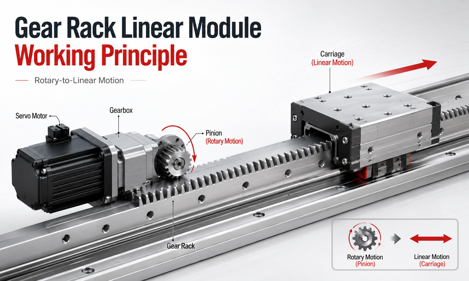
Agear rack linear moduleis a mechanical motion system that converts motor rotation into controlled linear movement through the meshing of a circular pinion gear and a straight gear rack. When the motor rotates the pinion, the gear teeth engage with the rack teeth and generate linear movement along the rack axis.
Unlike a ball screw system, which uses a rotating screw and traveling nut, or a timing belt system, which transfers motion through a toothed belt and pulleys, a gear rack drive transmits force directly through metal gear teeth. This operating principle makes gear racklinear modulesespecially suitable for long-stroke, high-speed and heavy-load industrial automation applications.
This article explains thegear rack linear module working principle, including rotary-to-linear motion conversion, pinion rotation, rack movement, gear meshing, module and tooth pitch, backlash, servo drive, encoder feedback and motion control.
What Is a Gear Rack Linear Module?
A gear rack linear module is a complete linear motion axis that integrates a gear rack transmission, pinion gear, guide rail, carriage, structural base, motor, gearbox, bearings, lubrication system, sensors andmotion controller.
The gear rack is a straight bar with evenly spaced teeth machined along its length. The pinion is a circular gear whose tooth profile matches the rack. When the pinion rotates, its teeth continuously enter and leave engagement with the rack teeth, producing linear displacement.
Depending on the mechanical design, either the pinion assembly moves along a fixed rack or the rack moves while the pinion remains stationary. In most industrial linear axes and gantry systems, the rack is fixed to the machine frame while the motor, gearbox, pinion and carriage move together.
How Does a Gear Rack Linear Module Work?
The operating process can be divided into several stages:
- The motion controller sends a position, speed or torque command to the servo drive.
- The servo drive supplies controlled electrical current to the servo motor.
- The servo motor generates rotary motion and torque.
- A gearbox may reduce the motor speed and increase the output torque.
- The motor or gearbox output shaft rotates the pinion gear.
- The pinion teeth mesh with the rack teeth.
- The rotational force of the pinion produces a tangential force along the rack.
- The carriage moves linearly along the guide rail.
- An encoder measures the actual motor position and speed.
- The control system continuously corrects any difference between the commanded and actual motion.
This combination of mechanical transmission and closed-loop servo control allows the gear rack linear module to perform rapid, accurate and repeatable linear movement.
Rotary-to-Linear Motion Conversion
The fundamental working principle of a rack and pinion system is the conversion of circular motion into straight-line motion.
The servo motor rotates the pinion around its center. At the point where the pinion contacts the rack, the rotating gear generates a tangential force. Because the rack cannot rotate, this tangential force causes relative linear movement between the pinion and rack.
If the rack is fixed, the pinion and carriage move along the rack. If the pinion is fixed, the rack moves linearly. The direction of movement depends on the direction of pinion rotation.
- Clockwise pinion rotation moves the carriage in one direction.
- Counterclockwise pinion rotation moves the carriage in the opposite direction.
- Increasing pinion speed increases the linear travel speed.
- Increasing the available pinion torque increases the linear driving force.
The conversion is positive and mechanically direct because the teeth of the pinion remain engaged with the teeth of the rack.
Pinion Rotation and Rack Movement
During operation, each pinion tooth enters contact with a rack tooth, transfers force and then exits the engagement area. The following teeth repeat this process continuously as the pinion rotates.
One complete revolution of the pinion produces a linear displacement equal to the pitch circumference of the pinion. The theoretical travel distance per revolution can be calculated as:
Linear travel per revolution = π × pitch diameter
Because the pitch diameter is determined by the gear module and the number of pinion teeth:
Pitch diameter = module × number of teeth
The travel distance can also be expressed as:
Linear travel per revolution = π × module × number of teeth
For example, a pinion with a module of 2 mm and 20 teeth has a pitch diameter of 40 mm. Its theoretical linear travel per revolution is approximately:
3.1416 × 40 mm = 125.66 mm
This relationship allows engineers to calculate the required motor speed, gearbox ratio and pinion size for a target linear velocity.
Gear Meshing Principle
Reliable motion depends on correct meshing between the pinion and rack. The tooth profiles must be geometrically compatible so that torque can be transferred smoothly without interference, tooth separation or excessive friction.
Most industrial gear rack systems use involute tooth profiles. An involute profile maintains a stable transmission ratio even when there are small changes in the center distance between the pinion and rack.
During correct meshing:
- The pinion and rack have the same module.
- The pressure angles are identical.
- The tooth pitch is compatible.
- The pinion axis is aligned correctly relative to the rack.
- The mounting distance produces the required tooth contact.
- The contact pattern is distributed across an appropriate portion of the tooth width.
Incorrect meshing can cause abnormal noise, vibration, uneven motion, premature wear, tooth edge loading, excessive backlash or even tooth damage.
Module and Tooth Pitch
The module is one of the most important parameters in a metric gear rack drive. It describes the size of the gear teeth and directly affects the load capacity, pinion diameter, transmission force and available positioning resolution.
The gear module is calculated as:
Module = pitch diameter ÷ number of teeth
The circular pitch is related to the module by:
Tooth pitch = π × module
A larger module produces larger and stronger teeth. It is generally suitable for higher loads, greater driving forces and more demanding operating conditions. However, a larger module may also increase the pinion diameter, module size, moving mass and minimum achievable mechanical resolution.
A smaller module provides finer teeth and may support smoother, more precise movement in lower-load applications. However, smaller teeth have lower individual tooth strength and require more careful alignment and lubrication.
| Parameter | Effect on the Gear Rack Axis |
|---|---|
| Larger module | Higher tooth strength and greater load capacity |
| Smaller module | Finer motion resolution and more compact pinion size |
| More pinion teeth | Larger pitch diameter and greater travel per revolution |
| Fewer pinion teeth | Smaller pitch diameter and higher theoretical linear force |
| Larger pressure angle | Higher tooth strength but greater radial force |
How Linear Speed Is Determined
The linear speed of a gear rack module depends on the pinion pitch diameter and rotational speed.
The theoretical linear speed can be calculated as:
Linear speed = π × pitch diameter × rotational speed
When rotational speed is measured in revolutions per minute, the result must be converted to the required linear speed unit.
A larger pinion moves the carriage farther with each revolution and therefore produces a higher linear speed at the same motor speed. However, a larger pinion also requires more torque to generate the same linear force.
A gearbox is often installed between the servo motor and pinion to balance speed, torque, motor inertia and positioning resolution. A higher reduction ratio increases the available output torque and improves motor-to-load inertia matching, but reduces the maximum pinion speed.
How Linear Driving Force Is Generated
The pinion applies a tangential force to the rack. The theoretical linear force is related to the output torque and pinion pitch radius:
Linear force = output torque ÷ pinion pitch radius
It can also be expressed as:
Linear force = 2 × output torque ÷ pinion pitch diameter
In practical calculations, transmission efficiency, friction, acceleration, external resistance and safety factors must also be considered.
A smaller pinion radius produces greater linear force for the same torque, while a larger pinion radius produces higher linear speed. This creates an important engineering tradeoff between speed and thrust.
What Is Backlash in a Gear Rack Drive?
Backlash is the mechanical clearance between the contacting sides of the pinion teeth and rack teeth. A small amount of clearance is normally required to prevent tooth interference, compensate for manufacturing tolerances and allow space for lubrication.
However, excessive backlash can reduce positioning accuracy and cause a delay when the direction of movement reverses. When the pinion changes rotational direction, it must first move across the tooth clearance before driving the opposite tooth surface.
Backlash can cause:
- Positioning error during direction reversal
- Reduced bidirectional repeatability
- Impact and vibration during acceleration changes
- Mechanical noise
- Uneven low-speed movement
- Lower contouring accuracy in multi-axis systems
The total backlash of the linear axis may come from the rack and pinion engagement, gearbox, couplings, bearings, mounting structure and guide system.
Backlash Reduction Methods
Industrial gear rack linear modules use several methods to reduce or eliminate transmission clearance.
Precision Ground Rack and Pinion
Ground gears have more accurate tooth geometry, smaller pitch errors and better surface quality than standard milled gears. They are commonly used in precision machine tools, laser processing systems and high-accuracy gantry axes.
Adjustable Pinion Engagement
The mounting position of the pinion can be adjusted toward the rack to control the tooth clearance. The adjustment must be performed carefully because excessive engagement can increase friction, noise, heat and tooth wear.
Spring-Loaded Preload
A spring or elastic mechanism applies continuous force between the pinion and rack. This helps maintain stable tooth contact despite small installation deviations.
Dual-Pinion Preload
Two pinions engage with the same rack and apply opposing torque. One pinion contacts one side of the rack tooth while the second contacts the opposite side. This arrangement can significantly reduce backlash and improve reversal accuracy.
Electronic Preload
In dual-motor systems, the motion controller applies a controlled torque difference between two servo-driven pinions. The opposing torque maintains contact on both sides of the rack teeth without relying only on mechanical springs.
Servo Motor Drive Principle
Most high-performance gear rack linear modules are driven by AC servo motors. The servo motor provides controlled torque, speed and angular position according to commands from the servo drive.
The drive receives motion commands from a programmable logic controller, CNC controller, industrial computer or dedicated motion controller. It then regulates the motor current and voltage to produce the required movement.
A typical servo-controlled gear rack axis includes:
- Motion controller
- Servo drive
- Servo motor
- Planetary gearbox
- Coupling or direct motor connection
- Pinion gear
- Gear rack
- Linear guide system
- Motor encoder
- Home and limit sensors
The servo system can execute acceleration, constant-speed travel, deceleration, positioning, synchronized motion and emergency stopping according to the programmed motion profile.
Encoder Feedback and Closed-Loop Control
An encoder is installed on or inside the servo motor to measure the angular position and rotational speed of the motor shaft. The servo drive compares the encoder feedback with the commanded position.
If a difference is detected, the controller changes the motor current to reduce the error. This process occurs continuously at high speed and forms a closed-loop control system.
The basic control process is:
- The controller calculates the target position.
- The servo drive commands the motor to rotate.
- The encoder measures the actual motor position.
- The drive calculates the position error.
- The motor torque is adjusted to reduce the error.
- The loop continues until the target position is reached.
A motor-mounted encoder measures the rotation of the motor shaft rather than the actual position of the carriage. Mechanical errors from gearbox backlash, rack pitch deviation, tooth clearance and structural deformation may therefore remain outside the motor feedback loop.
For higher positioning accuracy, a linear encoder can be installed along the machine axis. The linear encoder directly measures the actual carriage position and allows the controller to compensate for mechanical transmission errors.
Motion Control Process
The motion controller coordinates the complete operating cycle of the gear rack linear module. Before movement begins, it defines the target position, maximum speed, acceleration, deceleration and jerk limits.
A typical point-to-point positioning cycle includes:
- System initialization and safety inspection
- Homing to establish the mechanical reference position
- Calculation of the motion trajectory
- Acceleration from zero speed
- Constant-speed movement
- Controlled deceleration
- Final position correction
- Position holding
S-curve acceleration profiles are often used to reduce sudden changes in acceleration. This helps limit vibration, mechanical impact, gear tooth loading and structural deformation, especially on heavy gantry systems.
Homing and Limit Control
A gear rack axis normally uses sensors to establish the machine reference point and prevent overtravel.
- Home sensor:Establishes the reference position after startup.
- Positive limit sensor:Prevents movement beyond the positive travel boundary.
- Negative limit sensor:Prevents movement beyond the negative travel boundary.
- Mechanical stop:Provides final physical protection if electrical limit control fails.
During homing, the carriage moves toward the home sensor at a controlled speed. After the sensor is detected, the axis may reverse slowly to locate a more precise reference edge or encoder index pulse.
Why Gear Rack Drives Are Suitable for Long Stroke Motion
One of the main advantages of the gear rack working principle is that the rack can be manufactured and installed in multiple connected sections. This allows the motion axis to reach several meters or even tens of meters in length.
A ball screw becomes increasingly difficult to operate at high speed as its length increases because of screw whip, critical speed limits, rotational inertia and support requirements. A rack remains stationary, while only the pinion and carriage move along the axis.
Because the rack does not need to rotate, long-axis performance is not limited by the critical rotational speed of a long screw. This makesrack and pinion modulessuitable for:
- Largegantry robots
- CNC machine tools
- Laser cutting equipment
- Welding automation
- Heavy material handling
- Automated storage systems
- Long production lines
Rack Section Connection Principle
For long travel applications, several rack sections are installed end to end. Correct alignment at the connection points is essential because pitch errors or height differences can cause impact as the pinion passes between sections.
Installation usually involves:
- Using a reference surface to align the rack sections
- Using a matching rack or alignment tool across the joint
- Controlling the gap between adjacent sections
- Checking tooth pitch continuity
- Verifying the contact pattern along the full travel
- Measuring positioning error after assembly
A properly installed rack joint allows the pinion to move smoothly from one section to the next without noticeable vibration or noise.
Guide Rail and Gear Rack Functions
The gear rack transmits driving force, but it should not normally carry the complete external load of the carriage. Linear guide rails support the moving assembly and control its movement direction.
The guide system carries:
- Vertical load
- Horizontal load
- Pitching moment
- Yawing moment
- Rolling moment
Correct alignment between the guide rail and rack is critical. If they are not parallel, the pinion engagement depth changes along the travel, resulting in uneven resistance, vibration, noise and tooth wear.
Factors Affecting Positioning Accuracy
The theoretical position of a gear rack axis is calculated from the motor rotation, gearbox ratio, pinion dimensions and rack pitch. Actual positioning accuracy is affected by multiple mechanical and control factors.
- Rack pitch accuracy
- Pinion tooth profile accuracy
- Gearbox backlash
- Rack and pinion backlash
- Mounting straightness and parallelism
- Guide rail accuracy
- Structural stiffness
- Load-induced deformation
- Thermal expansion
- Servo tuning quality
- Encoder resolution
- Acceleration and speed settings
Precision applications may use ground racks, low-backlash planetary gearboxes, preload systems, linear encoders and software compensation tables to improve positioning performance.
Single-Drive and Dual-Drive Gantry Control
Wide gantry systems often use one gear rack linear drive on each side of the crossbeam. Two servo motors drive the left and right axes simultaneously.
The motion controller electronically synchronizes both sides to prevent the gantry beam from twisting or becoming misaligned. This control method is commonly called gantry synchronization or electronic gearing.
The controller compares the position feedback from both motors and continuously corrects the difference. In more advanced systems, linear encoders are installed on both sides to measure the actual beam position directly.
Dual-drive gantry control is particularly important when the crossbeam is wide, the load is heavy or the required acceleration is high.
Lubrication and Tooth Contact
Lubrication reduces friction and wear between the rack and pinion teeth. It also helps prevent corrosion, reduce noise and remove heat from the contact area.
Common lubrication methods include:
- Manual grease application
- Automatic lubrication pinions
- Oil lubrication systems
- Centralized grease systems
Insufficient lubrication can cause surface wear, pitting, increased noise and reduced service life. Excessive lubricant can attract dust, chips and abrasive particles, particularly in exposed machining environments.
The lubricant type and maintenance interval should be selected according to the operating speed, load, environment, rack material and manufacturer recommendations.
Advantages of the Gear Rack Working Principle
- Suitable for very long travel distances
- High linear speed capability
- Strong driving force and heavy-load capacity
- No long rotating screw and no screw critical-speed limitation
- Rack sections can be connected to extend the travel
- Suitable for horizontal, vertical and gantry configurations
- Supports single-axis and multi-axis automation systems
- Compatible with servo motors and closed-loop control
- Can achieve high accuracy with precision racks and feedback systems
Limitations of the Gear Rack Working Principle
- Backlash must be controlled in precision applications
- Gear meshing produces more noise than some belt or screw systems
- Correct alignment is essential during installation
- Exposed teeth require regular lubrication and protection
- Contamination may accelerate tooth wear
- Precision ground racks and preload systems increase cost
Gear Rack Drive Compared with Other Linear Drives
| Drive Type | Main Working Principle | Typical Strength | Typical Limitation |
|---|---|---|---|
| Gear rack | Rotating pinion drives a straight rack | Long stroke, high speed and heavy load | Backlash and gear noise |
| Ball screw | Rotating screw drives a recirculating ball nut | High positioning accuracy | Long-stroke speed limitation |
| Timing belt | Toothed belt transfers pulley rotation to the carriage | High speed and economical long travel | Lower rigidity under heavy load |
| Linear motor | Electromagnetic force directly produces linear movement | High acceleration and no mechanical transmission backlash | Higher cost and thermal management requirements |
Typical Applications
Gear rack linear modules are widely used in equipment that requires long travel, high speed, heavy loads or large structural dimensions.
- Gantry robots and Cartesian systems
- CNC routers and machining centers
- Laser cutting and plasma cutting machines
- Industrial welding systems
- Automated loading and unloading equipment
- Material handling systems
- Warehouse and logistics automation
- Large inspection platforms
- Packaging and production lines
- Heavy-duty pick-and-place systems
Key Selection Considerations
When selecting a gear rack linear module, engineers should evaluate the complete mechanical and control requirements rather than considering only travel length.
- Required stroke
- Payload and external forces
- Maximum speed
- Acceleration and deceleration
- Required positioning accuracy
- Repeatability
- Duty cycle
- Installation direction
- Allowable backlash
- Pinion module and number of teeth
- Gearbox reduction ratio
- Motor torque and inertia
- Guide rail load capacity
- Environmental contamination
- Lubrication method
- Safety factor
Frequently Asked Questions
How does a gear rack linear module convert rotation into linear motion?
The motor rotates a pinion gear that meshes with a straight gear rack. The tangential force between the gear teeth causes the pinion assembly or rack to move linearly.
What determines the travel distance per pinion revolution?
The travel distance is determined by the pinion pitch diameter. One pinion revolution theoretically produces a linear movement equal to the pitch circumference of the pinion.
Why is a gearbox used with a rack and pinion axis?
A gearbox increases output torque, reduces pinion speed, improves motor-to-load inertia matching and increases the effective positioning resolution of the servo system.
Does a gear rack drive have backlash?
Standard rack and pinion drives require a small amount of tooth clearance. Backlash can be reduced through precision gears, adjustable engagement, spring preload, dual-pinion preload or electronic preload.
Can a gear rack linear module achieve high positioning accuracy?
Yes. High accuracy can be achieved using ground racks, precision pinions, low-backlash gearboxes, rigid mounting, preload mechanisms, linear encoders and software error compensation.
Why is a gear rack drive suitable for long travel?
The rack remains stationary and can be installed in connected sections. The system is therefore not restricted by the critical rotational speed of a long ball screw.
What is the role of the encoder?
The encoder measures motor position and speed. The servo drive compares this feedback with the command signal and continuously adjusts motor torque to correct motion errors.
Conclusion
Thegear rack linear module working principleis based on direct mechanical engagement between a rotating pinion and a straight rack. Servo motor rotation is transmitted through the pinion teeth, producing controlled linear movement along the rack.
The module and tooth pitch determine the gear geometry, while the pinion diameter and motor speed determine the linear velocity. Motor torque and pinion radius determine the available driving force. Backlash, alignment, lubrication, structural stiffness and feedback accuracy directly influence positioning performance and service life.
By combining a precision rack and pinion transmission with servo drive, encoder feedback and advanced motion control, a gear rack linear module can provide long-stroke, high-speed and heavy-load movement for gantry robots, machine tools, material handling systems and large-scale industrial automation equipment.
