 English

Atiming belt linear moduleis a complete linear motion system that converts motor rotation into fast, controlled carriage movement. It is widely used in industrial automation because it can provide high speed, long travel, rapid acceleration, relatively low moving mass, and convenient integration into single-axis or multi-axis equipment.
Although the external structure of a belt drivenlinear modulemay appear simple, its performance depends on the correct interaction of many mechanical and electrical components. The timing belt transfers motion, the pulleys guide and drive the belt, the linear guide supports the load, the carriage provides the mounting platform, the bearings reduce rotational resistance, and the sensors define the operating limits.
Each component affects the module’s speed, positioning repeatability, load capacity, rigidity, noise, maintenance requirements, and service life. A poorly selected belt, pulley, bearing, guide rail, or motor mount can reduce the performance of the complete actuator even when the other components are correctly designed.
This guide explains the maintiming belt linear module components, including the timing belt, drive pulley, idler pulley, linear guide, guide block, carriage, bearings, motor mount, sensors, limit switches, fasteners, structural profile, tensioning mechanism, and protective components.
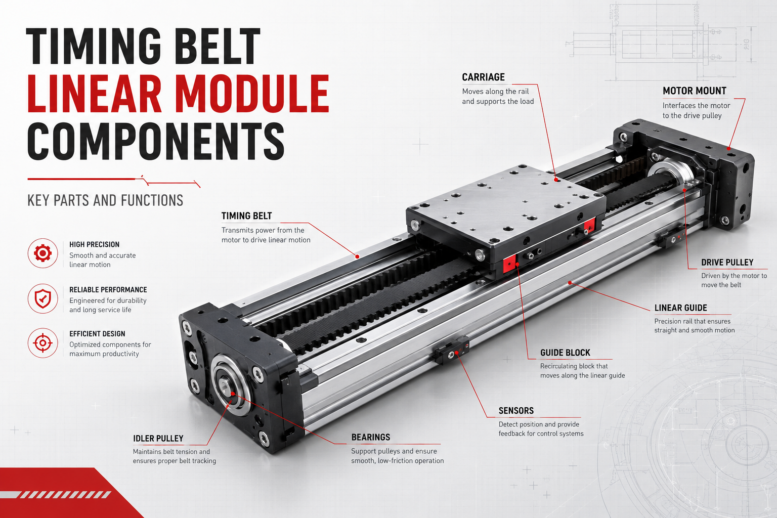
What Is a Timing Belt Linear Module?
A timing belt linear module is an integrated actuator that uses a toothed belt and pulley system to move a carriage along a linear guide.
The motor rotates the drive pulley. The drive pulley engages with the teeth of the timing belt and causes the belt to move around the pulley system. The carriage is mechanically connected to the belt, so it travels along the guide system as the belt moves.
Unlike an ordinary flat belt, a timing belt has shaped teeth that engage with matching grooves on the pulleys. This positive engagement reduces normal transmission slippage and helps maintain a predictable relationship between motor rotation and carriage movement.
Timing belt modulesare commonly used in packaging, pick-and-place automation, sorting systems, logistics equipment, loading and unloading machinery,gantry robots, labeling machines, visual inspection systems, electronics manufacturing, and other applications requiring fast point-to-point movement.
Main Components of a Timing Belt Linear Module
- Timing belt
- Drive pulley
- Idler pulley
- Belt tensioning mechanism
- Linear guide rail
- Guide blocks
- Moving carriage
- Structural base or aluminum profile
- Drive-end bearings
- Idler-end bearings
- Motor mount
- Motor coupling or direct-drive connection
- Home sensor
- Positive and negative limit switches
- Sensor brackets and triggering plates
- Fasteners and locating components
- Protective cover or sealing strip
- Lubrication components
- Cable management accessories
Timing Belt
The timing belt is the main transmission component of a belt driven linear module. It transfers motor torque from the drive pulley to the moving carriage.
The belt normally consists of a flexible polymer body, internal tensile cords, and molded teeth. The polymer provides flexibility and tooth shape, while the tensile cords resist elongation and carry the transmission load.
Main Functions of the Timing Belt
- Transmit motor torque
- Convert pulley rotation into carriage movement
- Connect the drive system to the moving carriage
- Support rapid acceleration and direction changes
- Enable long-stroke motion without a rotating screw shaft
- Maintain tooth engagement with the pulleys
Common Timing Belt Materials
Industrial timing belts are commonly made from polyurethane or rubber-based materials.
Polyurethane belts provide good wear resistance, dimensional stability, chemical resistance, and clean operation. They are frequently used in precision automation, electronics equipment, packaging systems, and clean production environments.
Rubber timing belts can provide good flexibility, vibration absorption, and economical performance. Their suitability depends on speed, load, temperature, contamination, and required service life.
Internal Tensile Cords
The tensile cords are embedded within the belt and carry most of the tension load. Common materials include steel wire, aramid fiber, fiberglass, and other high-strength cords.
Steel cords provide high tensile stiffness and low elongation, which can improve positioning stability. However, they require suitable pulley diameters and careful handling to avoid fatigue damage.
Aramid cords are lightweight and strong. They can reduce moving mass and may be useful in high-acceleration applications.
Belt Tooth Profile
The tooth profile must match the pulley groove profile. Common industrial tooth systems include trapezoidal and curvilinear profiles.
A mismatched belt and pulley can cause poor engagement, abnormal noise, accelerated wear, reduced torque capacity, tooth damage, and positioning errors.
Belt Width
Belt width affects allowable tension and transmission capacity. A wider belt can normally transmit more force, but it also requires wider pulleys, a larger module structure, and more installation space.
The correct belt width should be selected according to acceleration, payload, required thrust, pulley size, operating speed, duty cycle, and safety factor.
Belt Elongation
Timing belts do not normally slip when their teeth are correctly engaged, but they can still stretch elastically under load.
Elastic elongation may affect stopping stability, direction reversal, positioning accuracy, and servo tuning. The effect becomes more important with long strokes, high acceleration, heavy loads, and large external forces.
Common Timing Belt Failure Modes
- Tooth wear
- Tooth separation
- Cracking
- Edge fraying
- Tensile cord damage
- Permanent elongation
- Oil or chemical degradation
- Heat damage
- Contamination between belt and pulley
- Failure caused by incorrect tension
Drive Pulley
The drive pulley is connected to the motor and transfers motor torque to the timing belt. It is one of the most important components in the timing pulley system.
The pulley has grooves that match the belt tooth profile. As the pulley rotates, the teeth engage with the belt and pull it around the module.
Main Functions of the Drive Pulley
- Receive torque from the motor
- Engage with the timing belt
- Determine belt movement per motor revolution
- Influence speed, thrust, and positioning resolution
- Maintain stable transmission under acceleration
Pulley Diameter
The drive pulley diameter influences the linear distance traveled per motor revolution.
A larger pulley increases linear travel per revolution and can increase maximum speed. However, it also reduces mechanical force multiplication and may require more motor torque.
A smaller pulley can increase available linear force for a given motor torque, but it may reduce maximum speed and increase belt bending stress.
Pulley Tooth Count
Pulley tooth count is directly related to pitch diameter. It affects the transmission ratio, belt bending radius, motor speed requirement, and output thrust.
Using too few teeth may increase belt fatigue and reduce the number of teeth engaged under load. Using a much larger pulley may increase module dimensions and motor torque requirements.
Pulley Material
Timing pulleys are commonly manufactured from aluminum alloy, steel, or stainless steel.
Aluminum pulleys are lightweight and suitable for high-speed applications. Steel pulleys provide higher strength and wear resistance. Stainless steel may be used in corrosive, clean, or special production environments.
Pulley Bore and Motor Connection
The drive pulley can be connected to the motor shaft through a keyed bore, clamping hub, taper-lock system, spline, or integrated shaft structure.
The connection must prevent relative movement under acceleration and direction reversal. An insufficiently secured pulley can create backlash, unstable positioning, shaft wear, or complete transmission failure.
Pulley Runout
Excessive radial or axial runout can create belt tension variation, vibration, noise, uneven tooth loading, and positioning fluctuation.
The pulley must be manufactured accurately and installed concentrically with the shaft.
Idler Pulley
The idler pulley, also called the driven pulley or return pulley, is located at the opposite end of the module from the drive pulley.
It supports the belt loop, changes the belt direction, and helps maintain the correct transmission path.
Main Functions of the Idler Pulley
- Support the return side of the belt
- Guide the belt around the module
- Maintain belt alignment
- Provide part of the tensioning structure
- Reduce unnecessary belt vibration
Driven Pulley Alignment
The drive pulley and idler pulley must be parallel and correctly aligned. Misalignment can cause the belt to move sideways, wear against the pulley flange, produce abnormal noise, and damage the belt edges.
Idler Pulley Bearings
The idler pulley normally rotates on one or more bearings. Bearing quality influences rotational resistance, noise, temperature, and service life.
Damaged or contaminated bearings can create additional belt tension, vibration, and uneven carriage movement.
Belt Tensioning Mechanism
The tensioning mechanism adjusts and maintains the correct belt tension.
The belt must be tight enough to maintain tooth engagement and stable motion, but not so tight that it overloads the bearings, pulley shafts, belt cords, or structural profile.
Main Functions of the Tensioning Mechanism
- Remove excessive belt slack
- Maintain tooth engagement
- Reduce vibration and belt jumping
- Compensate for installation tolerance
- Allow belt replacement and adjustment
Common Tensioning Methods
- Adjustable idler pulley position
- Screw-based tension adjustment
- Sliding bearing housing
- Movable end plate
- Spring-assisted tensioning
- Carriage-side belt clamp adjustment
Insufficient Belt Tension
If the belt is too loose, it may vibrate, produce poor positioning stability, skip teeth under high load, or move laterally on the pulleys.
Excessive Belt Tension
If the belt is too tight, it can increase bearing load, motor torque requirement, friction, heat, noise, and tensile cord fatigue.
Correct tension should be set according to the belt manufacturer’s recommendations and the module’s load and speed conditions.
Linear Guide Rail
The linear guide rail supports the moving carriage and controls its travel direction. It is the primary load-bearing and guiding component of the timing belt module.
The belt generates movement, but the guide rail carries the payload. Without a suitable guide system, the belt would be exposed to side loads and moments that it is not designed to support.
Main Functions of the Linear Guide
- Support the carriage and payload
- Maintain straight-line movement
- Resist radial and lateral loads
- Resist pitch, yaw, and roll moments
- Reduce sliding friction
- Improve movement smoothness
- Maintain carriage alignment
Guide Rail Size
Guide rail size affects load capacity, rigidity, moment resistance, guide block dimensions, and module width.
A larger rail can support higher loads and moments, but it also increases module size, mass, and cost.
Guide Accuracy
The geometric accuracy of the guide system affects carriage straightness, parallelism, smoothness, and final machine performance.
The guide rail must be mounted on a sufficiently flat and rigid reference surface. An inaccurate base can distort the rail and create binding or uneven block loading.
Guide Preload
Preload reduces internal clearance between the rolling elements, guide block, and rail. Moderate preload can improve rigidity and positioning stability.
Excessive preload increases friction, heat, motor load, and wear. The correct preload depends on speed, accuracy, load, vibration, and duty cycle.
Guide Blocks
Guide blocks move along the linear guide rail and support the carriage.
Inside each block, recirculating balls or rollers travel through the load zone and return passage, allowing low-friction movement.
Main Functions of Guide Blocks
- Connect the carriage to the guide rail
- Support vertical and lateral loads
- Resist moment loads
- Maintain carriage alignment
- Provide low-friction linear movement
Number of Guide Blocks
A timing belt module may use one, two, or more guide blocks depending on the design.
Using multiple blocks can improve moment resistance and carriage stability. However, the blocks must be aligned correctly to avoid internal stress.
Guide Block Spacing
Longer spacing between guide blocks generally improves pitch and yaw moment resistance.
The spacing is limited by the carriage length, module structure, effective stroke, and overall dimensions.
Guide Block Seals
Guide block seals and scrapers help prevent dust and particles from entering the rolling contact area.
Damaged seals can allow contamination to enter the block and accelerate wear.
Moving Carriage
The carriage is the moving platform on which the payload, tooling, fixture, sensor, robot component, or another linear axis is mounted.
It connects the guide system to the belt transmission and transfers belt movement to the payload.
Main Functions of the Carriage
- Provide a mounting surface for the load
- Connect the belt to the guide blocks
- Distribute payload forces across the guide system
- Maintain tooling orientation
- Support multi-axis assembly
Carriage Material
Carriages are commonly made from aluminum alloy or steel.
Aluminum provides low mass and supports higher acceleration. Steel provides greater stiffness and strength but increases moving mass.
Carriage Dimensions
Carriage width and length influence mounting space, load distribution, rigidity, and moment capacity.
A larger carriage supports wider fixtures and can increase block spacing, but it reduces available stroke within a fixed module length.
Mounting Holes
The carriage normally includes threaded holes, locating holes, or reference edges.
Mounting hole positions should match the tooling design. Locating features can improve repeatability when fixtures are removed and reinstalled.
Belt-to-Carriage Connection
The carriage is usually connected to the belt through a belt clamp or toothed clamping plate.
The connection must distribute force without damaging the belt teeth or tensile cords. Loose clamping can cause lost motion, while excessive clamping can damage the belt.
Structural Base or Aluminum Profile
The structural base supports the guide rail, pulleys, bearings, motor mount, and carriage assembly.
Most timing belt modules use an extruded aluminum profile because it provides a good balance of stiffness, low weight, corrosion resistance, manufacturability, and cost.
Main Functions of the Structural Profile
- Support all module components
- Maintain pulley and guide alignment
- Provide mounting surfaces
- Protect internal components
- Resist bending and torsion
- Provide channels for sensors and accessories
Profile Rigidity
Profile rigidity affects straightness, vibration, settling time, load capacity, and positioning consistency.
Long modules require sufficient support along their length. A profile that is strong enough for a short stroke may deflect excessively when used over a much longer span.
Mounting Surface
The machine frame must provide a flat and rigid mounting surface. Tightening the module onto an uneven base can twist the profile and affect guide alignment.
Drive-End Bearings
Drive-end bearings support the drive pulley shaft and maintain its rotational position.
They absorb radial belt tension and may also resist axial loads depending on the shaft design.
Main Functions of Drive-End Bearings
- Support the pulley shaft
- Reduce rotational friction
- Maintain pulley alignment
- Resist belt tension load
- Support stable high-speed rotation
Bearing Selection Factors
- Pulley speed
- Belt tension
- Radial load
- Axial load
- Required life
- Lubrication method
- Temperature
- Contamination
- Noise requirements
Bearing Preload and Fit
Incorrect shaft fit or housing fit can cause bearing looseness, excessive preload, heat, noise, or early failure.
The drive shaft assembly must maintain concentricity between the pulley and bearings.
Idler-End Bearings
Idler-end bearings support the driven pulley and allow low-resistance belt return.
They may also be part of the movable tensioning structure.
Because the idler end is sometimes considered less critical than the motor end, poor-quality bearings may be overlooked. However, excessive idler resistance directly increases motor load and belt wear.
Motor Mount
The motor mount connects the servo motor or stepper motor to the timing belt module.
It must maintain the correct relationship between the motor shaft and drive pulley while resisting motor torque and vibration.
Main Functions of the Motor Mount
- Secure the motor to the module
- Maintain shaft alignment
- Resist motor reaction torque
- Support direct or parallel motor installation
- Provide access for installation and maintenance
Inline Motor Mount
In an inline configuration, the motor shaft is aligned with the drive pulley shaft. The connection may use a coupling or an integrated shaft.
This arrangement is mechanically simple but increases the overall module length.
Parallel or Folded Motor Mount
In a parallel configuration, the motor is installed beside the module and drives the pulley through a secondary timing belt and pulley set.
This reduces overall length but adds more transmission components and requires additional tension and alignment control.
Motor Mount Rigidity
A weak motor mount can flex under acceleration, creating vibration, alignment errors, and unstable servo performance.
Coupling and Shaft Connection
Some timing belt modules use a flexible coupling between the motor and drive shaft.
The coupling transmits torque while compensating for small alignment errors.
Coupling Requirements
- Sufficient torque capacity
- Low backlash
- Suitable rotational speed
- Controlled torsional stiffness
- Correct bore sizes
- Proper shaft clamping
A coupling with excessive elasticity can reduce response and positioning stability. A rigid coupling requires very accurate alignment.
Home Sensor
The home sensor provides a reference position for the control system.
When the machine starts or loses absolute position information, the carriage moves until the home sensor is triggered. The controller then establishes the axis reference position.
Main Functions of the Home Sensor
- Establish the machine coordinate reference
- Support homing after power-up
- Provide a repeatable starting position
- Help coordinate multiple axes
Common Home Sensor Types
- Inductive proximity sensor
- Photoelectric sensor
- Magnetic sensor
- Mechanical switch
- Encoder index combined with a proximity sensor
The home sensor should be mounted where it can be triggered reliably without becoming the normal mechanical end stop.
Positive and Negative Limit Switches
Limit switches define the allowable operating range of the carriage.
A positive limit switch protects one end of the stroke, while a negative limit switch protects the opposite end.
Main Functions of Limit Switches
- Prevent the carriage from exceeding the programmed stroke
- Reduce collision risk
- Provide electrical overtravel protection
- Protect the belt, carriage, and end plates
- Support safe commissioning
Limit switches should not be the only protection method. Mechanical end stops and software limits may also be required.
Sensor Brackets and Triggering Plates
Sensors require stable mounting brackets and correctly positioned triggering targets.
A loose sensor bracket can shift and change the detected position. A damaged or incorrectly shaped trigger plate can cause inconsistent detection.
Sensor positions should be adjustable during commissioning but secured against movement during operation.
Fasteners
Fasteners connect the structural profile, guide rail, carriage, motor mount, pulley housings, sensors, covers, and accessories.
Although fasteners are small components, they directly affect alignment, rigidity, safety, and long-term reliability.
Common Fasteners in Timing Belt Modules
- Socket head screws
- Countersunk screws
- Set screws
- Nuts and T-slot nuts
- Washers
- Dowel pins
- Retaining rings
- Thread-locking components
Fastener Torque
Insufficient tightening can lead to looseness, vibration, positioning drift, and component movement.
Excessive tightening can strip aluminum threads, deform components, damage bearings, or distort the guide rail.
Thread-Locking Measures
High-vibration applications may require thread-locking adhesive, locking washers, prevailing-torque nuts, or mechanical retention.
Protective Cover and Sealing Components
Timing belt modules may use top covers, sealing strips, stainless-steel bands, bellows, or side covers to protect the internal transmission and guide components.
Main Functions of Protective Components
- Reduce dust entry
- Prevent accidental contact
- Protect the belt and guide rail
- Improve appearance
- Reduce contamination from process debris
A cover does not automatically make the module fully sealed. The moving carriage opening, motor interface, sensor slots, and cable exits must also be considered.
Lubrication Components
The timing belt itself normally does not require lubrication, but the guide rail, guide blocks, and bearings may require grease or oil.
Common Lubrication Components
- Grease nipples
- Lubrication ports
- Oil lines
- Central lubrication fittings
- Guide block reservoirs
Incorrect lubrication can cause wear, heat, noise, contamination, and reduced service life.
Cable Management Accessories
A timing belt module often carries sensors, grippers, cameras, vacuum lines, or other moving equipment. These components require controlled cable and hose routing.
Common Cable Management Components
- Cable carriers
- High-flex cables
- Cable brackets
- Protective conduits
- Air and vacuum tubes
- Strain-relief clamps
Cable drag must be included in the load and thrust calculation. Poor routing can create additional moments, interfere with movement, or cause premature cable failure.
How the Components Work Together
When the motor receives a command, it applies torque to the drive pulley through the motor shaft or coupling.
The drive pulley engages with the timing belt and moves the belt around the pulley loop. The idler pulley supports the return path, while the tensioning mechanism maintains suitable belt tension.
The belt clamp transfers movement to the carriage. The carriage moves along the guide rail through the guide blocks, which support the payload and resist side forces and moments.
The bearings support smooth pulley rotation. Sensors detect the reference and travel limits. Fasteners maintain the alignment and rigidity of the complete structure.
The module performs correctly only when all these components are matched and assembled as a complete system.
Components That Most Affect Positioning Performance
- Belt tensile stiffness
- Belt tension
- Drive pulley accuracy
- Pulley shaft rigidity
- Bearing clearance
- Guide rail accuracy
- Guide block preload
- Carriage rigidity
- Belt clamp stability
- Motor encoder resolution
- Structural profile stiffness
A high-resolution motor cannot compensate completely for belt elasticity, pulley runout, loose fasteners, or structural deflection.
Components That Most Affect Speed
- Pulley diameter
- Motor speed
- Belt material
- Belt mass
- Carriage mass
- Bearing quality
- Guide preload
- Cable drag
- Profile rigidity
Components That Most Affect Load Capacity
- Guide rail size
- Guide block number and spacing
- Carriage rigidity
- Profile stiffness
- Belt width and tensile strength
- Pulley shaft capacity
- Bearing load rating
- Motor torque
Components That Most Affect Service Life
- Belt quality and tension
- Pulley alignment
- Bearing quality
- Guide lubrication
- Contamination protection
- Fastener security
- Motor and drive sizing
- Operating acceleration
- Load and moment distribution
Common Component-Related Problems
Carriage Positioning Drift
Possible causes include belt elongation, incorrect tension, loose pulley connection, loose belt clamp, bearing clearance, or sensor movement.
Abnormal Belt Noise
Possible causes include pulley misalignment, excessive belt tension, insufficient tension, damaged teeth, contaminated pulleys, or worn bearings.
Carriage Vibration
Possible causes include low structural rigidity, poor servo tuning, belt resonance, loose fasteners, damaged guide blocks, or excessive acceleration.
Belt Edge Wear
Possible causes include misaligned pulleys, tilted pulley shafts, incorrect belt installation, or lateral structural deformation.
Reduced Repeatability
Possible causes include belt elasticity, loose connections, incorrect tension, excessive load, temperature change, or guide wear.
High Motor Temperature
Possible causes include excessive belt tension, damaged bearings, excessive guide preload, high acceleration, insufficient motor capacity, or poor alignment.
Component Inspection Checklist
- Check belt surface and teeth
- Check belt tension
- Inspect belt edge wear
- Check drive pulley security
- Inspect pulley alignment
- Check drive and idler bearings
- Inspect guide rail lubrication
- Check guide block noise and clearance
- Inspect carriage fasteners
- Check belt clamp security
- Inspect motor mount rigidity
- Check coupling or shaft connection
- Test home and limit sensors
- Inspect sensor brackets
- Check profile mounting bolts
- Inspect protective covers
- Check cable carrier movement
How to Select Replacement Components
Replacement parts should match the original technical requirements rather than only physical dimensions.
Timing Belt Replacement
Confirm belt pitch, tooth profile, width, length, tensile cord material, and environmental compatibility.
Pulley Replacement
Confirm tooth profile, pitch, tooth count, width, bore size, hub design, material, and shaft connection.
Guide Rail and Block Replacement
Confirm rail size, accuracy grade, preload, block type, seal design, mounting dimensions, and lubrication requirements.
Bearing Replacement
Confirm bearing dimensions, load rating, speed rating, seal type, internal clearance, and fit requirements.
Sensor Replacement
Confirm sensing technology, supply voltage, output type, detection distance, connector, cable length, and environmental rating.
Frequently Asked Questions
What is the main transmission component in a timing belt linear module?
The timing belt is the main transmission component. It transfers motor torque from the drive pulley to the moving carriage.
What is the difference between the drive pulley and the idler pulley?
The drive pulley receives torque from the motor and moves the belt. The idler pulley supports the return side of the belt and helps maintain alignment and tension.
Does the timing belt support the payload?
The belt transfers motion but should not be used as the primary load-support component. The linear guide and guide blocks support the payload and resist side forces and moments.
Why does a timing belt module need a linear guide?
The linear guide controls carriage direction, supports the load, and prevents the belt from being exposed to unsuitable radial and moment loads.
What happens if the belt tension is too low?
Low tension can cause vibration, unstable positioning, poor tooth engagement, lateral belt movement, and possible tooth skipping under high load.
What happens if the belt tension is too high?
Excessive tension increases bearing load, motor torque, heat, friction, belt fatigue, and component wear.
Which component has the greatest effect on load capacity?
The guide rail, guide blocks, carriage, and structural profile have the greatest influence on payload and moment capacity. The belt, motor, pulleys, and bearings limit available drive force.
Which components require lubrication?
The linear guide, guide blocks, and some bearings require lubrication. The timing belt itself normally does not require lubrication.
Why are home and limit sensors necessary?
The home sensor establishes the reference position, while the limit sensors help prevent the carriage from moving beyond the allowable travel range.
Can different brands of belts and pulleys be combined?
They can only be combined when the pitch, tooth profile, width, and engagement requirements are fully compatible. Similar appearance does not guarantee correct operation.
Conclusion
A timing belt linear module is a coordinated mechanical and electrical system rather than a simple belt and pulley assembly.
The timing belt transfers movement, the drive pulley receives motor torque, the idler pulley supports the return path, and the tensioning mechanism maintains correct engagement. The linear guide and guide blocks support the payload, while the carriage provides the working platform.
Bearings ensure smooth pulley rotation, the motor mount maintains shaft alignment, sensors define the reference and travel limits, and fasteners preserve the rigidity and alignment of the complete structure.
Each component affects the module’s speed, positioning stability, load capacity, noise, maintenance, and service life. Reliable performance depends on correct component selection, accurate assembly, suitable belt tension, proper lubrication, and regular inspection.
By understanding the functions of the maintiming belt linear module components, engineers can select better products, diagnose faults more efficiently, plan maintenance correctly, and design more reliable high-speed linear motion systems.
