 English

Timing belt linear modulesare often grouped together as one product category, but their actual structures can be very different. An open belt axis for long-stroke transfer, a fully enclosed module for dusty automation, a compact belt stage for limited machine space and a dual-axis gantry system may all use timing belts while serving completely different mechanical requirements.
Understanding the maintiming belt linear module typeshelps engineers compare more than just stroke and speed. Enclosure style, guide arrangement, carriage structure, belt path, motor location and mounting orientation all affect stiffness, contamination resistance, maintenance access and system integration.
This guide explains the most common timing belt module configurations and shows how to match each design to the application.
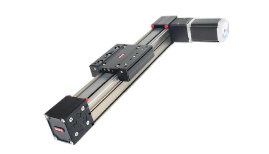
Timing Belt Linear Modules Can Be Classified in Several Ways
There is no single universal classification system. In practice, belt-drivenlinear modulesare usually compared from several structural dimensions at the same time:
- Open or enclosed construction
- Single-axis or dual-axis arrangement
- Standard or compact body design
- Single carriage or multiple carriage configuration
- Motor position and belt-routing arrangement
- Horizontal, vertical, side or inverted mounting
- Single-module or multi-axis Cartesian assembly
Selection principle:“timing belt module” describes the transmission method. The enclosure, guide structure and system configuration still need to be selected separately.
Open Timing Belt Linear Modules
An open belt module leaves more of the internal belt or guide area accessible. The structure is relatively simple and often easier to inspect and service.
Typical advantages include:
- Simple mechanical layout
- Easy visual inspection
- Convenient maintenance access
- Potentially lower cost
- Good suitability for clean, controlled factory environments
Where open modules work well
Open designs are often suitable for general transfer, pick-and-place, fixture positioning and automation cells where dust, chips and liquids are limited.
Main limitation
The exposed belt and guide area can be more vulnerable to contamination. Fine dust, metal particles, fibers or process debris may reduce belt and guide life if they enter the motion path.
Enclosed Timing Belt Linear Modules
An enclosed or covered module adds protective strips, top covers or integrated housings around the belt and guide mechanism.
The main purpose is not only appearance. Enclosure can help reduce direct exposure to contamination and keep moving components separated from the surrounding process.
Common benefits
- Improved protection from dust and debris
- Cleaner external appearance
- Reduced accidental contact with internal moving parts
- Better suitability for production environments with airborne contamination
- More controlled cable and sensor integration
Trade-offs
Enclosed structures can be more complex to service. Covers, sealing strips and access points add components that may require inspection over time.
Important:an enclosed module is not automatically dustproof, waterproof or cleanroom-rated. The final protection level depends on the actual sealing design and machine environment.
Open vs Enclosed Belt Modules
| Comparison | Open Module | Enclosed Module |
|---|---|---|
| Maintenance access | Usually easier | May require cover removal |
| Contamination protection | Lower | Generally better |
| Structure complexity | Simpler | More components |
| Application environment | Clean, controlled automation | Dustier or more protected production areas |
| Inspection visibility | High | Lower |
Standard-Profile Timing Belt Modules
Standard-profile belt modules use a relatively conventional aluminum beam or housing with integrated linear guides and a moving carriage.
They are designed as general-purpose axes and can cover a broad range of automation tasks.
Typical applications include:
- Material transfer
- Pick and place
- Packaging equipment
- Assembly lines
- Inspection fixtures
- Cartesian systems
Compact Timing Belt Modules
Compact designs reduce overall module height, width or motor envelope to fit smaller machines.
They are useful when installation space is more restrictive than payload capacity.
Where compact designs are useful
- 3C electronics equipment
- Desktop automation
- Inspection systems
- Small pick-and-place units
- Equipment with tight axis spacing
What compactness can change
A smaller body may have less structural section, smaller guide spacing or reduced room for larger bearings and belts. The design should therefore still be checked for moment load, stiffness and service access.
Single-Carriage Timing Belt Modules
The most common configuration uses one moving carriage on one linear module.
This is suitable when one tool, fixture or load must move along the axis.
Advantages include:
- Simple load calculation
- Simple cable routing
- Standardized carriage interface
- Easy integration with XY or XYZ systems
Multiple-Carriage Belt Modules
Some belt stages use two or more carriages on the same axis.
Depending on the design, the carriages may be mechanically linked, independently positioned through separate drives, or used to support one wide fixture.
Why use multiple carriages?
- Support a long or wide load
- Increase resistance to moment loads
- Carry two fixtures on one beam
- Build synchronized handling mechanisms
The exact behavior depends heavily on the belt routing and drive design, so the mechanical relationship between carriages should be confirmed before system design.
Single-Axis Timing Belt Modules
A single-axis module provides one linear degree of freedom. It is the basic building block for transfer, positioning and machine adjustment.
Typical uses include:
- Conveyor-side transfer
- Tray movement
- Camera positioning
- Tool adjustment
- Feeding and unloading
Dual-Axis Timing Belt Systems
A dual-axis configuration usually uses two parallel belt modules to support a wider moving structure or gantry beam.
This is common when one module alone cannot provide enough span or moment stability.
Typical uses
- Wide gantry systems
- Large pick-and-place frames
- Pallet handling
- Long crossbeam motion
Synchronization matters
If both sides are driven, the two axes must remain aligned. Synchronization can be mechanical or electronic.
Poor synchronization can twist the crossbeam and increase guide load.
Dual-axis rule:two strong modules do not automatically create a good gantry. Parallelism, synchronization and crossbeam stiffness must be designed together.
Timing Belt Modules in XY Systems
An XY system combines two perpendicular linear axes. One axis carries the second axis and the payload.
Timing belt modules are often used when the system needs:
- Long travel
- High speed
- Moderate payload
- Fast two-dimensional positioning
The lower axis must be sized for the mass of the upper axis, motor, cables, tooling and workpiece.
Timing Belt Modules in XYZ Systems
XYZ systems add a vertical or third-direction axis to create full Cartesian motion.
A common arrangement uses timing belt modules for the long X and Y travel, while the Z axis may use a ball screw or other structure if better vertical holding or thrust is required.
This mixed-drive approach is common because each axis can be optimized for its own job.
Horizontal Mounting Configurations
Horizontal installation is one of the most common orientations for timing belt modules.
Typical applications include transfer, gantry movement and positioning tables.
Important checks include:
- Payload
- Center-of-gravity offset
- Pitch, yaw and roll moments
- Acceleration
- Support spacing
Vertical Timing Belt Modules
Timing belt modules can also be used vertically, but vertical motion changes the load case.
The motor must work against gravity, and the system must consider what happens during power loss.
Depending on the application, the design may require:
- Motor brake
- Counterbalance
- Mechanical holding mechanism
- Safety-rated anti-fall measures
Vertical belt axes should be selected carefully because the belt is continuously supporting the suspended load.
Side-Mounted and Inverted Configurations
Some machines require the module to be installed on its side or upside down to save space or achieve a specific tooling arrangement.
These orientations can change:
- Guide load distribution
- Allowable moment load
- Lubricant distribution
- Contamination behavior
- Cable-carrier routing
Always use load and moment data that correspond to the real installation direction.
Motor Arrangement Is Another Configuration Choice
The motor does not always have to be mounted in line with the module.
Common layouts include:
- Inline motor
- Side-mounted motor
- Folded or parallel motor arrangement
- Motor with gearbox
Inline motor
Simple and direct, but increases the total axis length.
Folded motor
Reduces overall length by placing the motor beside the module. This is useful in compact machines but adds pulleys, belts or other transfer elements depending on the design.
Guide Structure Also Defines the Module Type
The timing belt provides drive force, but the linear guide carries the load and controls motion geometry.
Belt modules may use different guide concepts such as:
- Recirculating linear rails
- Integrated track systems
- Roller-based guidance
- Special low-friction guide structures
The guide type influences stiffness, load capacity, running resistance, maintenance and cost.
Wide-Body and High-Moment Designs
Some belt modules use wider profiles or larger guide spacing to improve resistance to moment loads.
These designs are useful when carrying:
- Large mounting plates
- Offset grippers
- Robot end effectors
- Wide fixtures
- Cross-axis assemblies
A wide-body module may be more appropriate than simply choosing a heavier motor if the real limitation is guide moment capacity.
Long-Stroke Belt Modules
One of the main advantages of belt drive is its suitability for long travel.
Unlike long ball screws, a belt does not need to rotate as one long shaft, so critical screw speed is not the limiting factor.
Long-stroke design still requires attention to:
- Belt tension
- Belt stretch
- Profile stiffness
- Support spacing
- Cable management
- Thermal effects
High-Speed Belt Modules
High-speed designs usually combine low moving mass, suitable pulley diameter, correct belt tension and a sufficiently rigid guide system.
Maximum speed alone does not define actual performance. Acceleration, deceleration, settling and load all influence the useful cycle time.
How to Choose Between Timing Belt Module Types
| Application Need | Configuration to Evaluate |
|---|---|
| Clean indoor transfer | Open standard module |
| Dustier factory environment | Enclosed or protected module |
| Limited machine space | Compact or folded-motor design |
| Wide load or large moment | Wide-body or dual-carriage design |
| Wide gantry structure | Dual-axis synchronized system |
| Long high-speed travel | Long-stroke belt module |
| Two-dimensional positioning | XY combination |
| Full Cartesian motion | XYZ or mixed-drive system |
Common Configuration Mistakes
Choosing enclosure only from appearance
An enclosed module should be selected because the process needs protection, not simply because it looks cleaner.
Using one module where a dual-axis structure is needed
A very wide fixture can create large moments. A dual-axis or wider guide arrangement may be more stable.
Ignoring motor envelope
The motor can interfere with guarding, adjacent axes or machine doors even when the module body fits.
Mounting a standard horizontal axis vertically without checking
Vertical use changes motor torque, brake requirements and load behavior.
Assuming all belt modules have the same precision
Guide design, belt stiffness, tension, profile rigidity and assembly quality all affect performance.
What QRXQ Needs to Recommend a Timing Belt Module Configuration
- Required stroke
- Payload and tooling mass
- Center-of-gravity position
- Maximum speed and acceleration
- Horizontal, vertical, side or inverted mounting
- Open or protected environment requirement
- Single-axis, XY, XYZ or gantry structure
- Available installation space
- Motor orientation preference
- Required repeatability
- Daily operating cycle
The best timing belt linear module type is defined by the complete machine layout.Enclosure, guide width, carriage arrangement, motor location and mounting direction can matter just as much as stroke and speed.
QRXQ evaluates timing belt module projects by combining application load, travel, dynamic performance and installation structure, then selecting the most suitable open, enclosed, compact, single-axis or multi-axis configuration.
