 English

Atiming belt linear moduleis a high-speed linear motion device that converts the rotary motion of a motor into controlled linear movement through a timing belt and pulley transmission system. Its mechanical structure combines the drive mechanism, linear guide system, moving carriage, aluminum base, end blocks, motor interface, belt tensioning mechanism, sensors, and protective components into a compact assembly.
Unlike aball screw linear module, which relies on a rotating screw and nut, a timing belt module transmits force through a toothed belt that moves between a drive pulley and an idler pulley. This structural arrangement enables long travel distances, high operating speeds, rapid acceleration, and relatively low moving mass.
Understanding thetiming belt linear module structureis essential when selecting, installing, maintaining, or integrating the module into an automation system. The rigidity of the aluminum profile, accuracy of the linear guide, belt tension, pulley alignment, carriage design, and motor mounting method all directly affect positioning performance, load capacity, service life, and operating stability.
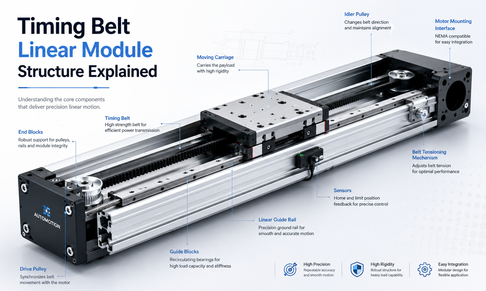
What Is the Basic Structure of a Timing Belt Linear Module?
A standard timing belt linear module generally consists of the following mechanical systems:
- Aluminum base profile
- Linear guide rail and guide blocks
- Timing belt transmission system
- Drive pulley and idler pulley
- Moving carriage
- Front and rear end blocks
- Motor mounting interface
- Belt tensioning mechanism
- Bearings and rotating support components
- Sensor and limit switch mounting components
- Protective cover or belt protection strip
- Fasteners and positioning components
These components are not independent. They form a coordinated mechanical system in which the motor generates torque, the pulley transmits motion to the timing belt, the belt drives the carriage, and the linear guide controls the carriage movement along a defined straight path.
Aluminum Base Profile
The aluminum base profile forms the main structural body of the timing belt linear module. It supports the guide rail, pulleys, end blocks, motor mount, sensors, and other mechanical components while maintaining alignment throughout the entire stroke.
Most timing beltlinear modulesuse an extruded aluminum alloy profile because it provides a practical balance between structural rigidity, weight, corrosion resistance, production cost, and manufacturing flexibility.
Main Functions of the Aluminum Profile
- Supports the linear guide and transmission components
- Maintains the straightness and alignment of the module
- Provides mounting surfaces for installation
- Protects internal components from external impact
- Reduces the overall weight of the motion axis
- Provides grooves for sensors, brackets, and accessories
The cross-sectional design of the profile has a major influence on module rigidity. Reinforcement ribs, wall thickness, internal cavities, mounting grooves, and guide rail support surfaces must be designed to resist bending and torsional deformation.
For long-stroke modules, insufficient profile rigidity can cause the base to sag under its own weight or under the applied load. This deformation may reduce positioning accuracy, create uneven guide loading, and increase belt tracking errors. Long axes may therefore require additional support points or a larger profile cross-section.
Linear Guide System
The linear guide system carries the external load and controls the direction of carriage movement. Although the timing belt provides the driving force, it should not be used as the primary load-supporting component.
A typical guide system consists of one or more linear guide rails and matching recirculating ball guide blocks. The guide rail is mounted along the aluminum base, while the guide blocks are connected to the moving carriage.
Functions of the Linear Guide
- Supports vertical, horizontal, and moment loads
- Maintains straight-line carriage movement
- Reduces friction during motion
- Improves repeatability and motion stability
- Prevents the carriage from rotating or tilting
- Separates the load-bearing function from the belt drive
The guide rail installation surface must be sufficiently straight and flat. Errors in the mounting surface can cause the guide rail to bend, creating uneven resistance, vibration, abnormal wear, and reduced service life.
Some compacttiming belt modulesuse a single guide rail with one or two guide blocks. Larger modules may use wider guide rails, multiple blocks, or dual-guide arrangements to increase rigidity and moment load capacity.
Timing Belt Transmission System
The timing belt transmission system is the central drive mechanism of the module. It normally includes a toothed timing belt, drive pulley, idler pulley, belt clamps, tensioning components, and supporting bearings.
The teeth on the belt engage with matching grooves on the pulleys. This positive engagement prevents the continuous slip associated with ordinary flat belts and allows the carriage position to correspond to the controlled rotation of the motor.
Timing Belt Construction
Industrial timing belts are usually manufactured from polyurethane or rubber-based materials. Internal tensile cords made from steel, fiberglass, aramid fiber, or other reinforced materials improve tensile strength and limit belt elongation.
The belt material and reinforcement structure affect:
- Maximum allowable tension
- Elastic deformation
- Positioning repeatability
- Operating noise
- Wear resistance
- Temperature resistance
- Expected service life
Polyurethane timing belts with steel reinforcement are commonly used in precision automation applications because they provide good wear resistance and relatively low elongation. Other belt materials may be selected for low-noise, high-temperature, cleanroom, or chemical-resistant environments.
Belt Tooth Profile
The tooth profile determines how the belt engages with the pulley. Common industrial profiles include trapezoidal and curvilinear tooth designs. Curvilinear profiles are often preferred in higher-performance systems because they can distribute load more smoothly and reduce stress concentration.
The belt pitch, belt width, tooth profile, and pulley diameter must be selected according to the required speed, acceleration, motor torque, payload, and transmission force.
Drive Pulley
The drive pulley is connected to the motor shaft either directly or through a coupling and shaft arrangement. As the motor rotates, the drive pulley pulls the timing belt and creates linear carriage movement.
The drive pulley must be accurately machined and concentrically mounted. Excessive radial runout or eccentricity can generate periodic speed variation, vibration, positioning error, and uneven belt tension.
Important Drive Pulley Parameters
- Number of pulley teeth
- Pitch diameter
- Outside diameter
- Tooth profile
- Pulley width
- Shaft connection method
- Material and surface treatment
- Rotational balance
A larger pulley diameter can reduce belt bending stress and improve belt life, but it also increases the distance traveled per motor revolution. A smaller pulley may provide a more compact structure and higher mechanical resolution, but it increases belt curvature and rotational speed.
Idler Pulley and Return End
The idler pulley is installed at the opposite end of the module from the drive pulley. It redirects the timing belt and completes the closed transmission loop.
In many designs, the idler pulley is integrated with the belt tensioning mechanism. Its position can be adjusted to increase or decrease belt tension.
The idler pulley assembly normally includes:
- Idler pulley
- Support shaft
- Rolling bearings
- Adjustment block
- Tensioning screw
- Locking fasteners
The idler pulley must remain parallel to the drive pulley. Misalignment can cause the belt to move sideways, rub against the pulley flange, produce abnormal noise, and wear unevenly.
Moving Carriage
The moving carriage is the platform that carries the workpiece, fixture, end effector, robot axis, dispensing head, camera, gripper, or other automation equipment.
The carriage is connected to both the linear guide blocks and the timing belt. The guide blocks support and guide the carriage, while the belt clamp transfers the driving force from the timing belt to the carriage.
Carriage Design Requirements
- Sufficient rigidity under external loads
- Accurate connection with guide blocks
- Reliable belt clamping
- Flat mounting surface
- Standardized threaded mounting holes
- Low moving mass
- Resistance to deformation during acceleration
The carriage must be rigid enough to prevent bending, but excessive carriage weight increases the moving mass. Higher moving mass requires greater motor torque, increases belt load, reduces acceleration capability, and may cause longer settling times.
The size and spacing of the guide blocks beneath the carriage determine its resistance to pitch, yaw, and roll moments. Applications with large overhung loads often require a longer carriage or multiple guide blocks.
Belt-to-Carriage Connection
The timing belt is normally connected to the carriage through a mechanical clamping plate. The clamp securely fixes one or both sides of the belt to the carriage without damaging the belt teeth or tensile cords.
A reliable belt clamp must prevent movement between the belt and carriage during acceleration, deceleration, emergency stopping, and direction reversal.
Improper belt clamping can result in:
- Carriage positioning drift
- Backlash during direction reversal
- Damage to belt teeth
- Local belt deformation
- Reduced transmission force
- Unexpected belt release
The clamping pressure should be distributed over a sufficient belt length. Concentrating the force in a small area can damage the belt reinforcement and shorten service life.
Front and Rear End Blocks
The end blocks are installed at both ends of the aluminum base profile. They support the pulley assemblies, bearings, motor connection, tensioning components, and mechanical stop structures.
End blocks also help close the internal space of the module and protect the belt transmission from external objects.
Main Functions of the End Blocks
- Support the drive and idler pulley shafts
- Maintain pulley alignment
- Connect the motor mount
- Provide belt tension adjustment
- Limit carriage travel
- Protect internal transmission components
- Provide mounting positions for covers and sensors
The dimensional accuracy of the end blocks is important because their bearing holes and mounting surfaces determine the position of the pulleys relative to the linear guide.
Motor Mounting Structure
The motor mounting structure connects the servo motor or stepper motor to the timing belt transmission. Depending on space limitations and installation requirements, the motor may be mounted in several configurations.
Direct Motor Mounting
In a direct-drive arrangement, the motor shaft is aligned with the drive pulley shaft. A flexible coupling may be used between the motor and pulley shaft.
This configuration provides a simple transmission path, high mechanical efficiency, and relatively low backlash. However, it increases the total module length because the motor extends from the end of the axis.
Folded or Parallel Motor Mounting
In a folded motor arrangement, the motor is installed parallel to the module body. A secondary timing belt and pulley set transfers torque from the motor to the main drive pulley.
This configuration reduces the overall installation length and is useful when the machine has limited end space. The additional transmission components, however, introduce more assembly requirements and additional belt tensioning considerations.
Bottom or Side Motor Mounting
Some modules position the motor below or beside the aluminum profile. This arrangement can improve equipment packaging and reduce interference with adjacent axes.
The selected motor mounting method must maintain shaft alignment and provide sufficient rigidity to prevent coupling vibration or pulley misalignment.
Belt Tensioning Mechanism
Correct belt tension is critical to the performance of a timing belt linear module. The tensioning mechanism removes excessive belt slack while maintaining enough flexibility for smooth pulley engagement.
Common tensioning methods include:
- Adjustable idler pulley position
- Movable end block
- Screw-driven tensioning block
- Sliding bearing support
- Dedicated belt tension adjustment plate
If the belt tension is too low, the system may experience backlash, tooth jumping, vibration, inaccurate positioning, and unstable direction reversal.
If the belt tension is too high, bearing loads increase, belt fatigue accelerates, motor torque demand rises, and the aluminum profile or pulley shaft may deform.
Belt tension must therefore be adjusted according to the belt manufacturer’s recommendations, module stroke, belt width, acceleration, payload, and operating orientation.
Bearing Support Structure
Bearings support the drive and idler pulley shafts and allow them to rotate with low friction. Their arrangement affects pulley stability, rotational accuracy, noise, and service life.
The drive end may use one or more bearings to resist radial belt forces and maintain shaft position. Applications with higher belt tension or higher torque may require larger bearings or a more rigid bearing support arrangement.
Improper bearing installation can cause:
- Abnormal rotational noise
- Pulley wobble
- Increased friction
- Motor overload
- Uneven belt tracking
- Reduced positioning repeatability
Sensor Mounting Structure
Timing belt linear modules normally include mounting positions for home sensors, positive limit sensors, negative limit sensors, and additional position detection devices.
Sensors may be installed in grooves along the aluminum profile or attached using adjustable brackets. A sensing plate or sensor target is mounted on the carriage.
Common Sensor Functions
- Establishing the machine home position
- Preventing overtravel
- Providing reference signals during initialization
- Confirming carriage arrival
- Supporting process interlocks
- Triggering external automation actions
The sensor position should be adjustable so that the effective travel range can be configured during installation. Sensor cables must also be routed away from moving parts, pulley surfaces, and belt paths.
Mechanical Stops and Travel Protection
Mechanical stops are often installed near the ends of the module as a final safety measure. They prevent the carriage from leaving the guide rail if the control system, sensor, or software limit fails.
Mechanical stops are not intended to absorb repeated high-speed impacts. Normal motion control should stop the carriage before it reaches the physical limit.
Some modules use elastic buffers, rubber dampers, or shock-absorbing components to reduce impact force during emergency overtravel.
Protective Components
Protective components reduce contamination and prevent foreign objects from entering the belt and guide system. The required level of protection depends on the operating environment.
Common protective structures include:
- Upper protective cover
- Stainless steel cover strip
- Flexible belt cover
- Side sealing strips
- End caps
- Dust-resistant guide protection
- Internal cable protection
Open timing belt modules provide convenient access and lower cost but expose the guide rail and belt to dust and debris. Semi-enclosed and fully enclosed modules provide better protection for industrial environments where particles, metal chips, or process contamination may be present.
For cleanroom applications, the module may require low-particle belts, special lubricants, sealed covers, vacuum extraction connections, and corrosion-resistant materials.
Open, Semi-Enclosed, and Enclosed Structural Designs
Open Structure
An open timing belt linear module has an exposed carriage, guide rail, or belt transmission. It is easy to inspect, clean, assemble, and maintain.
Open modules are suitable for relatively clean equipment environments where accessibility and cost are more important than contamination protection.
Semi-Enclosed Structure
A semi-enclosed module uses side walls, cover plates, or sealing strips to protect the internal guide and timing belt while allowing the carriage to move through an opening.
This design provides a balance between accessibility, protection, structural rigidity, and production cost.
Fully Enclosed Structure
A fully enclosed module provides a higher degree of protection against dust, debris, and accidental contact. The internal belt and guide components are largely isolated from the external environment.
Fully enclosed designs are commonly selected for packaging equipment, woodworking machinery, machining environments, and other applications where contamination control is important.
Single-Guide and Dual-Guide Structures
A compact timing belt module may use one linear guide rail mounted along the center of the aluminum profile. This design reduces width, weight, and cost.
A dual-guide design uses two parallel guide rails or a wider guide arrangement. It provides greater resistance to moment loads and improves carriage stability under offset loading.
The appropriate guide structure depends on:
- Payload
- Load center position
- Carriage dimensions
- Mounting orientation
- Acceleration
- Required rigidity
- Pitch, yaw, and roll moments
A single-guide structure may be sufficient for centrally mounted loads. A dual-guide structure is generally more suitable for wide tooling plates, cantilevered loads, or applications subject to significant moment forces.
How the Structural Components Work Together
When the motor rotates, torque is transferred to the drive pulley. The drive pulley moves the toothed timing belt around the closed transmission loop. Because the belt is fixed to the carriage, belt movement creates carriage movement.
The linear guide rail controls the direction of travel and supports the applied load. The end blocks hold the pulley shafts in alignment, while the tensioning mechanism maintains the required belt tension. Sensors monitor the carriage position, and protective components reduce contamination.
The complete motion sequence can be summarized as follows:
- Themotion controllersends a command to the motor drive.
- The servo motor or stepper motor generates rotary motion.
- The motor transmits torque to the drive pulley.
- The pulley teeth engage with the timing belt.
- The timing belt moves through the module.
- The belt clamp transfers motion to the carriage.
- The guide rail supports and guides the carriage.
- Sensors provide reference and limit signals.
- The controller regulates speed, acceleration, and final position.
Structural Factors Affecting Accuracy
Timing belt linear modules are generally selected for speed and long travel rather than micron-level positioning. However, their repeatability and motion stability can still be significantly improved through proper structural design.
Important structural factors include:
- Elastic elongation of the timing belt
- Rigidity of the aluminum profile
- Accuracy of the guide rail installation
- Drive pulley eccentricity
- Belt tension consistency
- Carriage rigidity
- Belt clamp stability
- Bearing clearance
- Motor coupling alignment
- Thermal expansion over long travel distances
Longer belts experience greater elastic deformation under the same applied force. For this reason, long-stroke modules may show greater positioning deviation during acceleration or under changing loads.
Closed-loop servo control and external position feedback can improve actual positioning performance, but they cannot fully compensate for poor mechanical rigidity, excessive belt elasticity, or structural misalignment.
Structural Factors Affecting Load Capacity
The timing belt transmits driving force, while the linear guide system carries the majority of the payload and moment load. The rated load of the module therefore depends on both the belt transmission and guide structure.
Load capacity is influenced by:
- Guide rail size
- Number of guide blocks
- Guide block spacing
- Carriage length and width
- Profile rigidity
- Belt width and reinforcement
- Pulley shaft strength
- Bearing capacity
- Mounting orientation
- Acceleration and deceleration
A module may be able to support a heavy static load but still be unsuitable for rapid acceleration. Dynamic force increases as the moving mass and acceleration increase, placing additional load on the belt, belt clamp, motor, bearings, and guide system.
Structural Factors Affecting Speed and Acceleration
Timing belt modules are widely used in high-speed automation because the belt transmission has relatively low rotational inertia and can support long travel without the critical-speed limitations associated with long ball screws.
High-speed structural design must consider:
- Belt tooth engagement
- Pulley balance
- Guide lubrication
- Carriage mass
- Profile vibration
- Bearing speed rating
- Motor torque and inertia matching
- Cable carrier resistance
- Stroke-end impact protection
A lightweight carriage improves acceleration but must still maintain adequate stiffness. Long unsupported profiles may vibrate at high speed, so additional mounting supports may be required.
Horizontal, Vertical, and Inverted Installation Structures
Horizontal Installation
Horizontal installation is the most common arrangement. The guide system supports the weight of the carriage and payload, while the belt mainly provides horizontal driving force.
Vertical Installation
In vertical applications, the timing belt must continuously resist gravity. A brake-equipped motor, counterbalance system, or additional safety mechanism may be required to prevent the carriage from falling during power loss.
The vertical moving mass must be included when calculating belt force, motor torque, and emergency stopping requirements.
Inverted or Side-Mounted Installation
Side-mounted and inverted installations change the direction of the load acting on the guide blocks. The guide system and carriage must be evaluated for the resulting moment loads.
Protective covers and lubrication methods may also need adjustment because grease distribution and contamination behavior can change with orientation.
Structural Design for Multi-Axis Systems
Timing belt linear modules are frequently integrated into XY platforms, XZ systems, XYZ gantries,Cartesian robots, and pick-and-place equipment.
In a multi-axis system, the lower axis must support not only the payload but also the complete mass of the upper axis, motor, cables, tooling, and accessories.
Structural planning should consider:
- Total moving mass
- Center of gravity
- Axis mounting interface
- Cross-beam rigidity
- Dynamic moment loads
- Cable carrier routing
- Motor interference
- Maintenance access
- Synchronization of parallel axes
For long-span gantry structures, two parallel timing belt axes may be synchronized mechanically or electronically. The supporting frame must maintain parallelism to prevent binding and uneven guide loading.
Timing Belt Module Assembly Considerations
Correct assembly is essential for ensuring that the individual structural components function as a coordinated motion system.
Important assembly steps include:
- Inspecting the aluminum profile mounting surfaces
- Installing and aligning the linear guide rail
- Mounting the guide blocks and carriage
- Installing the drive and idler pulley assemblies
- Routing the timing belt through the module
- Connecting the belt to the carriage clamp
- Adjusting belt tension
- Checking pulley parallelism
- Installing the motor and coupling
- Setting sensors and mechanical stops
- Testing carriage movement by hand
- Performing low-speed commissioning
The carriage should move smoothly across the full stroke without abnormal resistance. Belt tracking, guide resistance, bearing noise, and sensor operation should be checked before high-speed testing.
Common Structural Problems
Uneven Belt Tracking
Uneven tracking is often caused by misaligned pulleys, incorrect shaft positioning, uneven belt tension, or damaged pulley flanges.
Carriage Vibration
Carriage vibration may result from insufficient belt tension, excessive acceleration, loose fasteners, guide clearance, profile resonance, or unstable mounting.
Reduced Positioning Repeatability
Repeatability problems may be caused by belt elongation, loose belt clamps, pulley eccentricity, bearing clearance, insufficient structural rigidity, or changes in payload.
Abnormal Noise
Noise may come from worn bearings, dry guide blocks, belt rubbing, excessive belt tension, pulley misalignment, or damaged belt teeth.
Profile Deflection
Profile deflection usually occurs when the module has a long unsupported span or carries a load beyond the structural capacity of the aluminum base.
How to Evaluate a Timing Belt Linear Module Structure
When comparing timing belt modules, do not evaluate only the external dimensions or maximum speed. The internal mechanical design has a major influence on actual operating performance.
Important evaluation points include:
- Profile cross-section and rigidity
- Guide rail size and arrangement
- Number and spacing of guide blocks
- Belt material, width, and reinforcement
- Drive pulley diameter and machining accuracy
- Bearing support arrangement
- Carriage rigidity and mounting dimensions
- Belt tension adjustment method
- Motor mounting options
- Sensor installation flexibility
- Protection level
- Maintenance accessibility
A properly designed module should provide a balanced combination of speed, rigidity, repeatability, load capacity, service life, and installation convenience.
Timing Belt Module Structure Versus Ball Screw Module Structure
A timing belt module uses a flexible belt and pulley system, while a ball screw module uses a rigid screw and recirculating ball nut.
The timing belt structure is generally more suitable for:
- Long travel distances
- High-speed movement
- Rapid acceleration
- Material handling
- Packaging equipment
- Pick-and-place systems
The ball screw structure is generally more suitable for:
- Higher positioning accuracy
- Greater axial rigidity
- High thrust applications
- Precision assembly
- Machining and inspection equipment
- Short- to medium-stroke positioning
The appropriate structure should be selected according to the complete motion requirement rather than a single performance parameter.
Frequently Asked Questions
What supports the load in a timing belt linear module?
The linear guide rail and guide blocks support the payload and moment loads. The timing belt primarily transmits the driving force.
Why is belt tension important?
Correct belt tension reduces backlash, stabilizes direction reversal, prevents tooth jumping, and improves positioning repeatability. Excessive tension, however, can overload the bearings and shorten belt life.
Can a timing belt module be used vertically?
Yes. However, vertical applications require careful motor torque calculation and may need a brake motor, counterbalance, or fall-prevention mechanism.
What is the purpose of the aluminum profile?
The aluminum profile supports the guide rail, pulley assemblies, carriage, motor mount, and sensors while maintaining the structural alignment of the complete module.
Does the timing belt carry the payload?
The timing belt transfers the driving force but should not directly support the primary payload. The linear guide system carries the load.
Why do long-stroke timing belt modules require additional support?
Long aluminum profiles may bend or vibrate under their own weight and the applied load. Additional mounting supports help maintain straightness, rigidity, and stable guide operation.
What causes a timing belt to move sideways?
Sideways belt movement is commonly caused by pulley misalignment, shaft non-parallelism, uneven tension, damaged pulley surfaces, or incorrect belt installation.
Conclusion
Thetiming belt linear module structureis a coordinated combination of an aluminum base profile, linear guide system, timing belt transmission, moving carriage, pulley assemblies, motor mount, tensioning mechanism, sensors, bearings, and protective components.
Each component performs a specific function. The aluminum profile provides the structural foundation, the guide system supports and directs the load, the timing belt transmits motion, the carriage carries the working equipment, and the end blocks maintain pulley alignment and belt tension.
The performance of a belt-driven linear module depends not only on motor power or belt type, but also on the rigidity, accuracy, alignment, and integration of the complete mechanical structure. Proper structural selection helps achieve higher speed, stable repeatability, longer travel, lower maintenance requirements, and reliable operation in industrial automation systems.
