 English

Pick-and-place automation requires rapid movement, stable positioning and reliable handling over thousands or even millions of operating cycles. Whether the system transfers components between conveyors, loads parts into a machine tool or sorts products into different stations, the linear motion axis directly affects production speed and equipment reliability.
Timing belt linear modules are widely used in pick-and-place equipment because they combine high travel speed, fast acceleration, long stroke capability and flexible multi-axis integration. Compared with many screw-driven systems, a belt-driven module can perform frequent reciprocating motion over longer distances without being limited by screw critical speed.
This article explains how timing belt linear modules are applied in automated handling systems and how payload, cycle time, acceleration, repeatability, gripper integration and sensor control should be evaluated during system design.
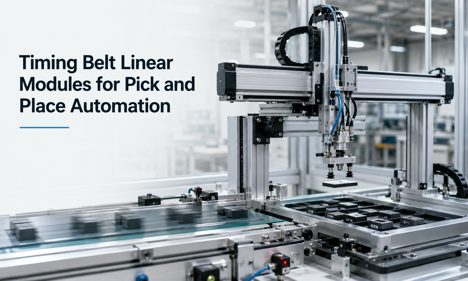
Why Timing Belt Linear Modules Are Suitable for Pick and Place
A typical pick-and-place process includes several repeated actions:
- Move to the pickup position.
- Stop and confirm the target position.
- Activate the gripper or vacuum tool.
- Move the workpiece to the placement position.
- Release the workpiece.
- Return for the next cycle.
Because this sequence may repeat continuously, the linear axis must accelerate, travel, decelerate and stop within a very short time. Timing belt modules are particularly suitable for this motion pattern because the moving carriage is driven by a lightweight toothed belt rather than a long rotating screw.
The main advantages include:
- High linear speed for short transfer times.
- Fast acceleration and deceleration.
- Low moving mass.
- Long available stroke.
- Quiet and smooth reciprocating motion.
- Flexible horizontal, vertical and multi-axis installation.
- Easy integration with servo motors, grippers and sensors.
High-Speed Reciprocating Motion
Pick-and-place equipment normally operates with short, repeated movements between fixed positions. The module may complete hundreds or thousands of reciprocating cycles during each production shift.
In a timing belt module, the motor rotates a drive pulley. The pulley engages with the teeth of the belt and converts rotary motion into linear carriage movement. Because the belt and pulley system has relatively low rotational inertia, the axis can respond quickly to servo commands.
The achievable operating speed depends on several factors:
- Motor rated speed and available torque.
- Drive pulley diameter.
- Transmission ratio.
- Belt type and belt pitch.
- Stroke length.
- Payload and moving mass.
- Guide rail capacity.
- Required stopping distance.
Maximum catalog speed should not automatically be used as the actual operating speed. A practical design must also consider vibration, settling time, payload stability and the distance required for acceleration and deceleration.
Cycle Time Calculation
Cycle time is one of the most important parameters in pick-and-place automation. It determines the number of parts the equipment can handle per minute or per hour.
A complete cycle may include:
- Acceleration time.
- Constant-speed travel time.
- Deceleration time.
- Position settling time.
- Gripper closing time.
- Pickup confirmation time.
- Gripper opening time.
- Return movement time.
The total cycle time can be expressed as:
Tcycle= Toutbound+ Tpickup+ Treturn+ Trelease+ Tsettling
For longer travel distances, the motion profile is usually trapezoidal. The carriage accelerates to the selected speed, travels at constant speed and then decelerates before reaching the target position.
For short strokes, the axis may not have enough distance to reach the programmed maximum speed. In this case, the motion profile becomes triangular, consisting only of acceleration and deceleration.
When estimating cycle time, engineers should use the actual motion profile rather than dividing stroke by maximum speed. A module with a very high maximum speed may not reduce cycle time significantly when the travel distance is short and acceleration is limited.
Payload and Moving Mass
The payload includes more than the transferred workpiece. The complete moving mass should include:
- Workpiece weight.
- Gripper or vacuum tool.
- Mounting plate.
- Pneumatic valves and fittings.
- Vision camera or inspection sensor.
- Cable carrier moving section.
- Additional vertical axis, when installed.
For a horizontal axis, the motor mainly overcomes acceleration force, friction and external resistance. A simplified force calculation is:
F = m × a + Ffriction+ Fexternal
Where:
- Fis the required linear driving force.
- mis the total moving mass.
- ais the required acceleration.
For vertical motion, gravity must also be considered:
F = m × a + m × g + Ffriction
A vertical timing belt axis should normally include a brake motor or another holding mechanism to prevent the carriage from falling during power loss.
Acceleration and Deceleration
High acceleration can shorten transfer time, but excessive acceleration may create unwanted effects:
- Belt stretch.
- Carriage vibration.
- Workpiece movement inside the gripper.
- Higher motor torque demand.
- Increased bearing and guide loads.
- Longer settling time after stopping.
- Reduced service life of mechanical components.
The selected acceleration should therefore balance production speed with mechanical stability. Delicate, liquid-filled or loosely held products usually require smoother acceleration than rigid metal components.
S-curve motion profiles are often used to reduce mechanical shock. Instead of changing acceleration abruptly, an S-curve profile controls jerk and produces smoother transitions during starting and stopping.
Positioning Repeatability
Many pick-and-place applications do not require extremely high absolute positioning accuracy, but they do require consistent repeatability. The carriage must return to the same pickup and placement positions during every cycle.
Repeatability is influenced by:
- Belt tooth engagement.
- Belt tension.
- Belt stiffness.
- Pulley machining quality.
- Linear guide precision.
- Servo tuning.
- Encoder resolution.
- Payload variation.
- Frame rigidity.
- Mounting surface flatness.
For general material transfer, packaging and sorting, timing belt modules normally provide sufficient repeatability. Applications requiring micron-level positioning, precision dispensing or highly accurate machining may be better suited to a ball screw or linear motor system.
To maintain stable repeatability, the module should be mounted on a rigid and level structure. Belt tension, pulley alignment and guide lubrication should also be checked according to the maintenance schedule.
Gripper Integration
The end-effector is the component that directly interacts with the product. Common handling tools include:
- Pneumatic parallel grippers.
- Electric grippers.
- Vacuum suction cups.
- Magnetic grippers.
- Fork-type handling tools.
- Custom mechanical fixtures.
The gripper can be mounted directly on the carriage or on a secondary vertical axis. The mounting plate should provide sufficient rigidity while keeping moving mass as low as possible.
Integration design should consider:
- Gripper weight and center of gravity.
- Required opening and closing time.
- Air hose and cable routing.
- Workpiece detection.
- Collision clearance.
- Tool replacement requirements.
- Emergency release behavior.
For pneumatic tools, the response time of valves and air lines can influence the total cycle time. Locating the valve close to the gripper can reduce air volume and improve response speed.
For vacuum handling, the system should include vacuum confirmation and loss-of-vacuum detection. This prevents the axis from moving away before the workpiece has been securely picked up.
Sensor and Control Integration
Sensors provide position references, safety protection and process confirmation. A typical timing belt pick-and-place axis may include:
- Home position sensor.
- Positive and negative limit sensors.
- Workpiece presence sensor.
- Gripper open and closed sensors.
- Vacuum pressure switch.
- Collision or overload detection.
- Servo encoder feedback.
The home sensor establishes a repeatable machine reference after startup. Limit sensors prevent the carriage from traveling beyond the usable stroke. Mechanical end stops may also be installed as secondary protection.
Servo motors are commonly used when programmable speed, acceleration and accurate positioning are required. The servo drive communicates with a PLC,motion controlleror industrial computer through pulse commands, fieldbus communication or real-time motion networks.
A typical control sequence may be:
- Confirm that the target workpiece is present.
- Move the carriage to the pickup coordinate.
- Activate the gripper.
- Confirm successful pickup.
- Move to the placement coordinate.
- Release the workpiece.
- Confirm release.
- Return to the next pickup position.
Interlocks should prevent movement when the gripper state, workpiece state or downstream station is not ready.
Multi-Axis Pick-and-Place Systems
Timing belt modules can be combined into multi-axis systems for more complex handling tasks.
Single-Axis Transfer
A single horizontal axis transfers products between two fixed stations. This arrangement is common in conveyor loading, packaging and part sorting.
XZ Pick-and-Place System
An XZ system combines a horizontal transfer axis with a vertical lifting axis. The horizontal axis moves between stations, while the vertical axis lowers the gripper to pick up or place the product.
XY Positioning System
An XY system moves products between multiple coordinates on a horizontal plane. It is suitable for tray loading, sorting, inspection and pallet arrangement.
XYZ Gantry System
An XYZ system adds vertical movement to the XY platform. It can access multiple pickup and placement positions within a three-dimensional working area.
Dual-Drive Gantry
Wide gantry systems may use two synchronized timing belt axes to drive both sides of a crossbeam. Electronic synchronization or a mechanical transmission shaft is used to prevent gantry skew.
When designing a multi-axis system, engineers should evaluate the combined moving mass. For example, the lower axis may need to carry the complete upper axis, motor, gripper and workpiece.
Common Pick-and-Place Applications
Timing belt linear modules are used in a wide range of automated handling processes, including:
- Loading and unloading CNC machines.
- Transferring parts between conveyors.
- Electronic component handling.
- Packaging and carton loading.
- Battery cell and module transfer.
- Tray loading and unloading.
- Vision inspection positioning.
- Product sorting and classification.
- Assembly line material feeding.
- Palletizing and depalletizing.
- Medical consumable handling.
- Warehouse and logistics automation.
Timing Belt Module Selection Factors
A suitable module should be selected according to the complete motion requirement rather than only the workpiece weight.
| Selection Parameter | Design Consideration |
|---|---|
| Stroke | Include pickup distance, placement distance, safety clearance and overtravel allowance. |
| Payload | Calculate the workpiece, gripper, tooling, mounting plate and additional moving components. |
| Speed | Use the required production cycle rather than the maximum catalog speed alone. |
| Acceleration | Check motor torque, belt load, workpiece stability and settling time. |
| Repeatability | Match the module capability with the allowable pickup and placement tolerance. |
| Mounting Orientation | Confirm whether the axis operates horizontally, vertically or at an angle. |
| Allowable Moment | Evaluate overhung grippers, offset loads and the center of gravity. |
| Environment | Consider dust, moisture, temperature, cleanroom requirements and chemical exposure. |
| Duty Cycle | Confirm the number of cycles per minute and total operating hours. |
| Motor and Controller | Select the servo power, brake, encoder and communication method. |
Allowable Moment and Load Offset
Grippers are often mounted away from the center of the carriage. This creates pitch, yaw or roll moments on the guide system.
Even when the payload is below the nominal load capacity, an excessive load offset can overload the guide blocks. The center of gravity should therefore be kept as close to the carriage as possible.
For long or heavy tooling, engineers may use:
- A wider module.
- Two parallel guide rails.
- A larger carriage.
- Dual synchronized modules.
- An external support structure.
Installation and Commissioning
Correct installation is essential for high-speed reciprocating operation. The mounting surface should be flat, rigid and free from distortion.
During commissioning:
- Check that the module is securely mounted.
- Confirm pulley alignment and belt tension.
- Move the carriage slowly through the complete stroke.
- Verify sensor positions and signal logic.
- Confirm the gripper and cable carrier clearance.
- Start with low speed and low acceleration.
- Gradually increase the motion parameters.
- Monitor vibration, noise, motor load and settling behavior.
- Validate pickup and placement repeatability.
- Run a continuous cycle test under actual payload.
Servo parameters should be tuned with the actual tooling and workpiece installed. Tuning an unloaded axis may produce unstable behavior after the payload is added.
Maintenance for Continuous Operation
Pick-and-place equipment often operates continuously, making preventive maintenance especially important.
Routine maintenance should include:
- Inspecting belt wear and tooth condition.
- Checking belt tension.
- Inspecting drive and idler pulleys.
- Lubricating linear guides.
- Checking carriage fasteners.
- Inspecting cable carriers and air hoses.
- Cleaning dust and process debris.
- Testing home and limit sensors.
- Monitoring abnormal noise and vibration.
- Reviewing servo alarms and motor load trends.
An increase in positioning variation, noise or motor current may indicate belt looseness, guide contamination, pulley wear or mechanical misalignment.
Timing Belt Modules Compared with Other Drive Systems
| Drive Type | Main Strength | Typical Limitation |
|---|---|---|
| Timing Belt | High speed, long stroke and fast reciprocating movement. | Lower rigidity and absolute accuracy than precision screw systems. |
| Ball Screw | High positioning accuracy, rigidity and thrust. | Speed and stroke may be limited by screw critical speed. |
| Gear Rack | Long travel, heavy load and scalable stroke. | Requires careful backlash and gear meshing control. |
| Linear Motor | Very high acceleration, high speed and direct drive response. | Higher cost and more demanding thermal and control requirements. |
For general automated transfer, packaging, sorting and machine loading, timing belt modules often provide the best balance between speed, stroke, cost and integration flexibility.
Conclusion
Timing belt linear modules are an effective motion solution for pick-and-place automation requiring fast reciprocating movement, long travel and flexible multi-axis integration. Their low moving inertia allows rapid acceleration, while the belt drive supports longer strokes without the critical speed limitations associated with long ball screws.
Successful system design depends on more than selecting a module with sufficient nominal payload. Engineers must evaluate the complete moving mass, cycle time, acceleration profile, positioning repeatability, load offset, gripper response, sensor logic and mounting orientation.
When properly selected, installed and maintained, atiming belt linear modulecan provide stable and efficient operation for machine loading, conveyor transfer, packaging, sorting, assembly and other high-cycle material handling applications.
