 English

Printing and textile machines often combine long travel, repeated reversing motion and continuous material flow. A printhead may scan back and forth across a substrate, a coating head may traverse over a web, or a textile handling mechanism may need to move in synchronization with rollers, feeders and winding equipment.
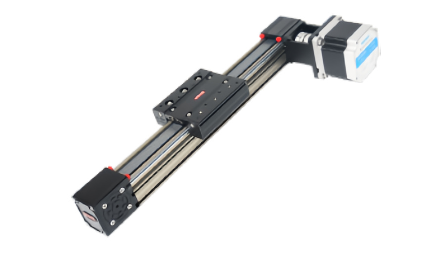
These applications are a natural fit fortiming belt linear modules in printing machinerybecause belt-driven axes can provide long stroke, high speed and relatively low moving mass without the critical-speed limits associated with long rotating screws.
However, good performance depends on more than maximum travel speed. Print quality, coating uniformity and fabric handling can all be affected by velocity ripple, vibration, belt elasticity, synchronization error and structural deflection. This guide explains how timing beltlinear modulesare used in printing and textile equipment and what should be checked before selecting them.
Why Timing Belt Modules Fit Printing and Textile Motion
Many printing and textile processes require an actuator to move repeatedly across a wide working area while the product itself continues to advance.
Typical advantages of timing belt drive include:
- Long travel capability
- High linear speed
- Fast direction reversal
- Relatively low moving inertia
- Simple multi-axis integration
- Efficient use of long machine frames
Application principle:printing and textile axes should be selected around motion smoothness and synchronization, not only top speed. A fast axis that vibrates or changes velocity through the process can reduce product quality.
Printing-Head Motion: Speed Must Remain Controlled
Digital printing systems may move a printhead carriage across paper, film, fabric, labels or other media.
A belt-driven stage can be effective because the carriage can remain relatively light and move quickly over a long width.
Important motion requirements often include:
- Repeatable scan position
- Stable scanning velocity
- Low vibration
- Fast reversal outside the active print zone
- Low carriage mass
- Predictable cable and ink-line behavior
Constant velocity matters inside the print zone
If print firing or image placement is synchronized to carriage position, speed variation can influence dot spacing and registration.
The motion profile can therefore be divided into two zones:
- Process zone:prioritize smooth, predictable velocity.
- Turnaround zone:use stronger acceleration and deceleration to reduce non-printing time.
This approach can improve throughput without forcing the active printing section to use unnecessarily aggressive dynamics.
Why Reversal Behavior Matters in Bidirectional Printing
Many print systems reverse direction at the edge of the work area.
Repeated reversal can expose:
- Belt compliance
- Insufficient belt tension
- Carriage vibration
- Structural resonance
- Servo following error
If the process prints in both directions, reversal-related positioning differences may affect registration.
Correct belt tension, rigid carriage support and suitable servo tuning are therefore important for consistent bidirectional motion.
Coating-Head Linear Motion
Coating and dispensing systems may move a head across film, foil, paper, textile or other continuous web materials.
Acoating linear modulecan be used to:
- Traverse a coating head across the web
- Position a nozzle bank
- Adjust application width
- Move inspection or measurement heads
- Support recipe-based product changeover
Path smoothness influences coating consistency
If material flow remains constant while carriage speed changes, the deposited amount per unit length may also change.
For continuous coating, important axis characteristics include:
- Low speed ripple
- Smooth acceleration
- Stable traverse velocity
- Low vibration
- Good straightness
Process rule:when coating quality depends on material deposited per unit distance, motion speed becomes part of the process parameter—not only a machine parameter.
Traverse Winding and Level-Wind Systems
Winding equipment may use a traversing linear axis to guide wire, yarn, tape, film or fiber evenly across a reel.
In these systems, the linear axis is not working independently. It must maintain a defined relationship with spindle rotation.
Typical requirements include:
- Accurate traverse pitch
- Stable synchronization with reel rotation
- Controlled reversal at reel edges
- Adjustable winding pattern
- Long continuous duty
Traverse speed is linked to spindle speed
If the reel rotates faster, the traverse axis may need to move faster to preserve the desired winding pitch.
This makes electronic gearing or coordinated motion control useful in many winding systems.
Synchronization Is Central to Winding Quality
A synchronized belt module may be controlled from spindle position, line speed or another master axis.
Possible control strategies include:
- Electronic gearing
- Electronic camming
- Master-follower control
- PLC motion synchronization
Mechanical accuracy alone cannot guarantee winding quality if the control timing between rotary and linear axes is inconsistent.
Textile Handling and Fabric Transfer
Textile machinery often handles lightweight but flexible materials that can wrinkle, stretch or shift if motion is too abrupt.
Timing belt modulescan be used for:
- Fabric positioning
- Cutting-head movement
- Inspection camera travel
- Gripper transfer
- Edge handling
- Automatic loading and unloading
Flexible materials require gentle motion
High acceleration may cause a fabric edge or unsupported section to oscillate even when the carriage itself is stable.
Motion profiles should therefore consider the mechanical behavior of the textile, not just the module.
Cutting and Marking Heads
Large-format textile and printing systems may use timing belt axes to move cutting knives, markers, lasers or inkjet heads.
These applications often combine:
- Long X-axis travel
- High traverse speed
- Frequent direction changes
- Moderate tool mass
- Path-following requirements
A timing belt axis is often attractive when the tool does not require very high process thrust and long travel is more important than maximum structural stiffness.
When Timing Belt Drive Is a Strong Choice
| Application | Why Belt Drive Fits |
|---|---|
| Wide-format printhead scanning | Long travel and fast reversing |
| Coating-head traverse | Smooth long-stroke motion |
| Traverse winding | Continuous synchronized motion |
| Textile inspection | Long camera travel with moderate load |
| Cutting-head movement | High speed and lightweight carriage |
| Material transfer | Efficient long-distance positioning |
When Another Drive Type May Be Better
Timing belt modules have clear strengths, but another transmission may be more suitable when the process requires:
- Very high thrust
- Very high structural stiffness
- Extremely tight absolute positioning
- Very low-speed precision scanning
- Minimal elastic transmission compliance
Ball screw or linear motor systems may be preferable depending on stroke, load and precision.
Belt Elasticity and Registration Accuracy
Timing belts stretch elastically under force.
Elastic displacement becomes more important when:
- The travel length is long
- The carriage mass is high
- Acceleration is aggressive
- The belt is narrow or has lower tensile stiffness
In printing, this can influence registration after direction changes or during changing dynamic loads.
For precise registration, use suitable belt stiffness, stable tension and feedback appropriate to the process.
Motor Encoder vs Linear Feedback
Most belt-driven axes use motor-side encoder feedback. This is effective for controlling motor position and speed.
However, a motor encoder does not directly measure belt stretch or carriage position after the transmission.
For demanding registration or measurement applications, a linear encoder can provide more direct carriage-position feedback.
| Feedback Method | Main Strength | Main Limitation |
|---|---|---|
| Motor encoder | Simple, common and effective for general motion | Does not directly observe belt elasticity |
| Linear encoder | Measures carriage position more directly | Higher integration cost and complexity |
Servo Control Is Usually Preferred for Synchronized Motion
Printing, coating and winding systems often benefit from servo motors because they support:
- Closed-loop position control
- Stable speed control
- Electronic gearing
- Electronic camming
- Rapid reversal
- Master-follower synchronization
Stepper motors can still be useful for simple adjustment axes or lower-dynamic positioning tasks.
Machine Frame Stiffness Affects Print and Coating Quality
A precise belt stage mounted on a flexible beam can still produce poor process results.
Structural deflection can cause:
- Printhead height variation
- Coating-gap variation
- Camera focus change
- Long settling time
- Tool-path deviation
For wide machines, crossbeam stiffness should be evaluated under both static tool weight and dynamic acceleration.
Wide Gantries May Need Dual-Axis Drive
Large printing and textile machines may use two parallel X axes supporting one crossbeam.
This can improve load distribution, but the two sides must remain synchronized.
Important checks include:
- Mechanical parallelism
- Crossbeam stiffness
- Dual-axis homing
- Electronic synchronization
- Emergency-stop behavior
Dual-drive rule:control synchronization cannot compensate for a mechanically twisted or poorly aligned gantry.
Dust, Fiber and Ink Mist Affect Maintenance
Printing and textile environments can expose the module to paper dust, lint, fibers, coating residue, ink mist and adhesive contamination.
These contaminants can affect:
- Linear guides
- Belt teeth
- Pulley grooves
- Cover strips
- Sensors
Enclosed timing belt modules can provide additional protection, but enclosure design does not automatically guarantee complete contamination resistance.
Open vs Enclosed Modules
Open modules
Open structures are easier to inspect and clean but expose the belt and guide more directly to fibers and dust.
Enclosed modules
Enclosed structures can reduce direct contamination, but internal inspection and cleaning may require more maintenance access.
The choice should be based on the actual process environment.
Guide Lubrication and Belt Maintenance Are Different
The timing belt normally operates dry, while the linear guide usually requires lubrication.
Maintenance should include:
- Guide lubrication according to the module specification
- Belt tension inspection
- Belt tooth and edge inspection
- Pulley alignment checks
- Removal of lint and debris
Do not apply grease to the belt as a general maintenance practice.
Long Continuous Duty Changes the Maintenance Strategy
Winding and textile equipment may run continuously for long production shifts.
Maintenance intervals should consider:
- Total travel distance
- Reversal count
- Operating hours
- Acceleration level
- Belt tension stability
- Guide lubrication condition
- Environmental contamination
A lightly loaded traverse axis may still accumulate very high fatigue exposure because it reverses continuously.
Synchronization With Web Speed
Some printing and coating machines need the linear axis to maintain a fixed relationship with web speed.
Examples include:
- Registration correction
- Cross-web scanning
- Pattern tracking
- Traverse coating
- Winding pitch control
The controller may use an encoder on the web roller or spindle as a master reference, while the belt axis follows a calculated position profile.
A Practical Selection Sequence
- Define the process.Printing, coating, winding, inspection, cutting or transfer?
- Define stroke and machine width.
- Calculate moving mass and tool overhang.
- Set maximum speed and acceleration.
- Define active process-zone speed stability.
- Check reversal and settling requirements.
- Define synchronization with rollers or spindles.
- Select belt profile, width and pulley size.
- Size motor torque, speed and inertia.
- Check frame and crossbeam stiffness.
- Evaluate dust, lint, ink or coating contamination.
- Plan maintenance by actual travel distance and reversal count.
What QRXQ Needs to Evaluate a Printing or Textile Belt Axis
- Machine function
- Required stroke
- Moving head or carriage mass
- Maximum speed and acceleration
- Process-zone speed requirement
- Required repeatability or registration accuracy
- Reversal frequency
- Synchronization requirement
- Single-axis or dual-gantry configuration
- Dust, fiber, ink or coating environment
- Motor and controller preference
- Daily operating hours
In printing and textile machinery, the best belt axis is not simply the fastest one.It is the axis that combines long travel, smooth process-zone motion, repeatable reversal and reliable synchronization with the rest of the machine.
QRXQ evaluates printing and textile timing belt modules from the complete process sequence, matching belt drive, servo control, structural stiffness and contamination protection to the actual production task.
