 English

Timing belt linear modulesare widely used in industrial automation because they can provide high-speed, long-stroke linear motion. However, selecting a motor or pulley based only on the advertised maximum speed of the module may result in insufficient acceleration, inaccurate cycle-time estimates, excessive vibration or motor overload.
A complete timing beltlinear modulespeed calculation should consider motor speed, pulley pitch diameter, pulley tooth count, belt pitch, transmission ratio, acceleration, deceleration, travel distance and auxiliary process time. This guide explains the main formulas and provides practical calculation examples for engineering selection.
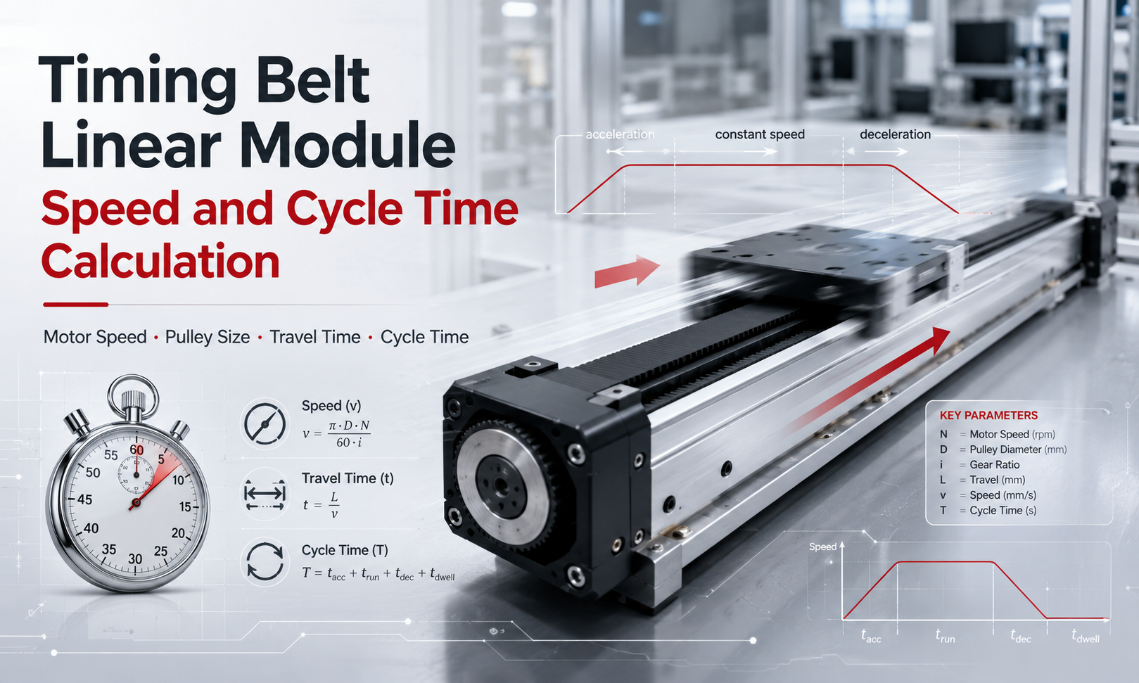
1. Key Parameters Used in Speed Calculations
Before calculating linear speed and cycle time, define the following parameters:
| Symbol | Parameter | Typical Unit |
|---|---|---|
| nm | Motor rotational speed | rpm |
| np | Drive pulley rotational speed | rpm |
| Dp | Pulley pitch diameter | mm |
| z | Number of pulley teeth | teeth |
| p | Timing belt pitch | mm |
| i | Transmission reduction ratio | dimensionless |
| v | Linear travel speed | mm/s or m/s |
| a | Acceleration | m/s² |
| d | Deceleration | m/s² |
| L | Travel distance | mm or m |
| T | Travel or cycle time | s |
In this article, the transmission ratio is defined as:
i = motor revolutions ÷ pulley revolutions
For example, a 2:1 reduction ratio means the motor rotates twice while the drive pulley rotates once, soi = 2.
2. Relationship Between Motor Speed and Pulley Speed
When the motor drives the timing pulley directly, the pulley speed is equal to the motor speed:
np= nm
When a gearbox, belt reduction or other transmission mechanism is installed, the pulley speed is:
np= nm÷ i
Where:
nmis the motor speed in rpm.npis the drive pulley speed in rpm.iis the reduction ratio.
A larger reduction ratio reduces the linear speed but increases the torque available at the drive pulley. Therefore, the transmission ratio must be selected by considering both speed and load requirements.
3. Linear Speed Based on Pulley Pitch Diameter
Each revolution of the drive pulley moves the timing belt by one pitch circumference. The theoretical linear speed is calculated as:
v = π × Dp× np ÷ 60
If the pulley pitch diameter is entered in millimeters, the result is in millimeters per second:
v = π × Dp× nm÷ (60 × i)
To convert millimeters per second to meters per second:
v (m/s) = π × Dp× nm÷ (60 × i × 1000)
Example
Assume the following conditions:
- Motor speed: 3000 rpm
- Pulley pitch diameter: 31.83 mm
- Direct drive:
i = 1
The theoretical linear speed is:
v = π × 31.83 × 3000 ÷ 60
v ≈ 5000 mm/s = 5 m/s
This is the theoretical belt speed. The allowable operating speed may be lower because of payload, guide capacity, belt rating, stroke length, structural rigidity and motor torque.
4. Linear Speed Based on Belt Pitch and Pulley Teeth
In practical engineering calculations, it is often easier and more accurate to use the timing belt pitch and pulley tooth count.
The belt travel per pulley revolution is:
Srev= z × p
Therefore, the linear speed is:
v = z × p × np ÷ 60
Including the transmission ratio:
v = z × p × nm÷ (60 × i)
Where:
zis the number of pulley teeth.pis the timing belt pitch in millimeters.nmis the motor speed in rpm.
Example
Consider a timing belt module using:
- 20-tooth drive pulley
- 5 mm belt pitch
- 3000 rpm motor speed
- Direct drive
The belt travel per revolution is:
Srev= 20 × 5 = 100 mm/rev
The theoretical speed is:
v = 20 × 5 × 3000 ÷ 60
v = 5000 mm/s = 5 m/s
This result is equivalent to the calculation based on a 31.83 mm pulley pitch diameter because:
Dp= z × p ÷ π
Always use the pulley pitch diameter rather than the pulley outside diameter. The outside diameter does not directly represent the effective belt travel per revolution.
5. Calculating the Required Motor Speed
When the required linear speed is known, the motor speed can be calculated in reverse.
nm= 60 × v × i ÷ (z × p)
If the linear speed is entered in meters per second:
nm= 60 × v × 1000 × i ÷ (z × p)
Example
A timing belt module must operate at 2.5 m/s. It uses a 20-tooth pulley, a 5 mm pitch belt and a 2:1 reduction ratio.
nm = 60 × 2.5 × 1000 × 2 ÷ (20 × 5)
nm= 3000 rpm
The selected servo motor must therefore be capable of maintaining approximately 3000 rpm while delivering the required torque.
6. Theoretical Maximum Speed and Actual Operating Speed
The speed calculated from motor rpm and pulley size is only the theoretical transmission speed. The actual maximum operating speed should be determined by the lowest limit in the entire motion system:
vmax= min(vmotor, vbelt, vguide, vstructure, vprocess)
The main limiting factors include:
- Maximum continuous and peak motor speed
- Motor torque available at high speed
- Timing belt allowable speed and tooth engagement
- Pulley diameter and bearing speed
- Linear guide speed and lubrication condition
- Payload mass and installation orientation
- Module stroke and structural vibration
- Required positioning accuracy and settling time
- Cable carrier and external component speed limits
- Process requirements such as dispensing, inspection or pick-and-place stability
A motor may reach its rated speed without carrying a load, but it may not provide enough torque to accelerate the actual payload at that speed. Motor torque-speed characteristics must therefore be checked together with the speed calculation.
7. Acceleration and Deceleration Time
A timing belt module cannot instantly reach its commanded speed. It requires an acceleration stage and a deceleration stage.
For constant acceleration from zero speed:
ta= v ÷ a
The acceleration distance is:
La= v² ÷ (2a)
For constant deceleration to zero speed:
td= v ÷ d
The deceleration distance is:
Ld= v² ÷ (2d)
Where:
tais acceleration time.tdis deceleration time.Lais acceleration distance.Ldis deceleration distance.
These formulas describe a simplified trapezoidal motion profile. Servo systems frequently use S-curve acceleration to reduce shock and vibration. An S-curve profile normally requires more time than the ideal constant-acceleration calculation because jerk is limited.
8. Trapezoidal Motion Profile Travel Time
A trapezoidal motion profile contains three stages:
- Acceleration
- Constant-speed travel
- Deceleration
The module can reach the commanded speed when the travel distance satisfies:
L ≥ La+ Ld
The constant-speed travel distance is:
Lc= L - La- Ld
The constant-speed travel time is:
tc= Lc÷ v
The total theoretical travel time is:
Ttravel= ta+ tc+ td
Calculation Example
Assume a timing belt linear module has the following motion requirements:
- Travel distance: 1.2 m
- Commanded speed: 2 m/s
- Acceleration: 4 m/s²
- Deceleration: 5 m/s²
Acceleration time:
ta= 2 ÷ 4 = 0.5 s
Acceleration distance:
La= 2² ÷ (2 × 4) = 0.5 m
Deceleration time:
td= 2 ÷ 5 = 0.4 s
Deceleration distance:
Ld= 2² ÷ (2 × 5) = 0.4 m
Constant-speed distance:
Lc= 1.2 - 0.5 - 0.4 = 0.3 m
Constant-speed time:
tc= 0.3 ÷ 2 = 0.15 s
Total theoretical travel time:
Ttravel= 0.5 + 0.15 + 0.4 = 1.05 s
The module therefore requires approximately 1.05 seconds to complete the one-way movement, excluding positioning settling time, controller delay and process time.
9. Triangular Motion Profile for Short Strokes
For a short stroke, the module may begin decelerating before it reaches the commanded maximum speed. In this case, the velocity profile is triangular rather than trapezoidal.
When the starting and ending speeds are zero, the achievable peak speed is:
vpeak= √(2 × L × a × d ÷ (a + d))
The travel time is:
Ttravel= vpeak÷ and + vpeak÷ d
The calculated peak speed must be compared with the commanded speed:
- If
vpeak≥ v, use the trapezoidal profile calculation. - If
vpeak< v, the module cannot reach the commanded speed within the available stroke.
This is why increasing the programmed maximum speed may have little effect on cycle time in a short-stroke application. Higher acceleration may provide a greater cycle-time improvement than higher maximum speed.
10. Complete Cycle Time Calculation
Production cycle time includes more than the module travel time. A complete cycle may include outbound travel, process time, return travel, positioning stabilization, clamping and controller delays.
A general cycle-time formula is:
Tcycle= Tout+ Tprocess+ Treturn+ Tsettling+ Tauxiliary
Auxiliary time may include:
- Workpiece clamping and release
- Gripper opening and closing
- Vacuum generation and confirmation
- Vision inspection
- Dispensing, welding or marking
- PLC communication delay
- Sensor confirmation
- Servo positioning and settling
Cycle-Time Example
Using the previous one-way travel time of 1.05 seconds:
- Outbound travel: 1.05 s
- Process dwell: 0.20 s
- Return travel: 1.05 s
- Home-position dwell: 0.10 s
The complete cycle time is:
Tcycle= 1.05 + 0.20 + 1.05 + 0.10 = 2.40 s
The theoretical production rate is:
Cycles per hour = 3600 ÷ Tcycle
Cycles per hour = 3600 ÷ 2.40 = 1500 cycles/hour
The actual production rate should include equipment availability, material supply, operator intervention, inspection delays and other process losses.
11. Effect of Pulley Size on Module Speed
A larger drive pulley moves more belt per revolution, increasing linear speed at the same motor rpm. However, increasing pulley size also changes the torque and acceleration requirements.
The drive force available from the pulley is approximately:
F = T ÷ r
Where:
Fis the tangential drive force.Tis the pulley torque.ris the pulley pitch radius.
For the same motor torque, a larger pulley radius produces less linear drive force. Therefore:
- A larger pulley increases linear speed.
- A smaller pulley increases available linear force.
- A larger pulley may require a higher-torque motor.
- A pulley that is too small may reduce belt life because of excessive bending.
Pulley selection must balance speed, torque, acceleration, belt life, tooth engagement and module dimensions.
12. Effect of Transmission Ratio
A reducer changes both pulley speed and output torque.
The pulley speed is:
np= nm÷ i
Ignoring efficiency losses, the pulley torque is approximately:
Tp= Tm× i
Considering transmission efficiency:
Tp= Tm× i × n
Whereoris the transmission efficiency.
A higher reduction ratio improves output torque and acceleration capability but reduces maximum linear speed. A lower reduction ratio increases speed but requires the motor to provide more torque directly.
13. Why Actual Cycle Time May Differ from the Calculation
Theoretical formulas are useful for initial sizing, but actual motion may take longer because of:
- S-curve jerk settings
- Servo control response
- Positioning tolerance and settling time
- Motor torque limitations
- Payload variation
- Belt elasticity
- Guide friction and lubrication
- Cable drag
- Controller scan time
- Communication and sensor delays
- Mechanical vibration at high speed
For preliminary design, it is advisable to add a cycle-time margin. The required margin depends on the control system, process complexity and application stability requirements.
14. Common Speed Calculation Mistakes
Using the pulley outside diameter
Linear speed should be calculated using the pulley pitch diameter or the product of belt pitch and pulley tooth count. Using the outside diameter introduces calculation errors.
Ignoring acceleration distance
Dividing stroke by maximum speed assumes constant-speed travel over the entire stroke. This significantly underestimates travel time in short-stroke applications.
Using the motor no-load speed
The motor may not maintain its maximum rpm under load. The torque-speed curve must be checked at the required operating point.
Ignoring the transmission ratio
A gearbox or external belt reduction changes the pulley speed. The reduction ratio must be included in the linear-speed calculation.
Ignoring return and process time
One-way motion time is not equal to the complete production cycle time. Return motion, dwell time, gripper action and positioning stabilization must be included.
Assuming higher speed always reduces cycle time
In short-stroke applications, the module may never reach the programmed maximum speed. Increasing acceleration or reducing process delay may be more effective.
15. Recommended Speed Selection Procedure
- Define the stroke, payload, orientation and required cycle time.
- Calculate the linear speed required by the process.
- Select the timing belt pitch and pulley tooth count.
- Calculate the required pulley and motor speed.
- Check the motor torque-speed curve.
- Calculate acceleration and deceleration distances.
- Determine whether the motion profile is trapezoidal or triangular.
- Calculate one-way and return travel time.
- Add process, dwell, settling and controller time.
- Verify belt load, guide load, vibration and positioning accuracy.
- Apply a suitable engineering safety margin.
- Confirm the result through actual motion testing.
16. Summary of Main Formulas
| Calculation | Formula |
|---|---|
| Pulley speed | np= nm÷ i |
| Travel per pulley revolution | Srev= z × p |
| Linear speed | v = z × p × nm÷ (60 × i) |
| Required motor speed | nm= 60 × v × i ÷ (z × p) |
| Acceleration time | ta= v ÷ a |
| Acceleration distance | La= v² ÷ (2a) |
| Deceleration time | td= v ÷ d |
| Deceleration distance | Ld= v² ÷ (2d) |
| Triangular profile peak speed | vpeak= √(2 × L × a × d ÷ (a + d)) |
| Production rate | Cycles per hour = 3600 ÷ Tcycle |
17. Frequently Asked Questions
How is timing belt linear module speed calculated?
Multiply the pulley tooth count by the belt pitch and pulley rotational speed, then divide by 60. If a reducer is used, divide the motor speed by the transmission ratio before calculating the linear speed.
Should pulley outside diameter or pitch diameter be used?
Use the pulley pitch diameter. Alternatively, calculate the belt travel per revolution using the pulley tooth count multiplied by the belt pitch.
Why does the module not reach the programmed maximum speed?
The stroke may be too short to complete the acceleration stage, or the motor may have insufficient torque at high speed. Controller acceleration, jerk and load settings may also limit the achievable speed.
How can cycle time be reduced?
Cycle time can be reduced by optimizing acceleration, deceleration, stroke, process dwell, positioning settling time and auxiliary actions. Increasing maximum speed alone may not significantly improve short-stroke motion.
Does a larger pulley always provide better performance?
No. A larger pulley increases linear speed but reduces the linear force available from the same motor torque. It may also increase motor torque requirements and module dimensions.
How much margin should be added to the calculated cycle time?
The margin depends on themotion controller, payload variation, process requirements and settling accuracy. Theoretical calculations should be verified through servo sizing and actual machine testing.
Conclusion
Timing belt linear module speed is mainly determined by motor speed, pulley pitch circumference and transmission ratio. However, accurate cycle-time calculation must also include acceleration, deceleration, stroke length, motion profile, return travel and auxiliary process time.
For long-stroke motion, maximum speed can have a major influence on cycle time. For short-stroke motion, acceleration and deceleration usually have a greater effect. The final selection should be verified by checking motor torque, belt capacity, guide performance, vibration, positioning accuracy and actual operating conditions.
