 English

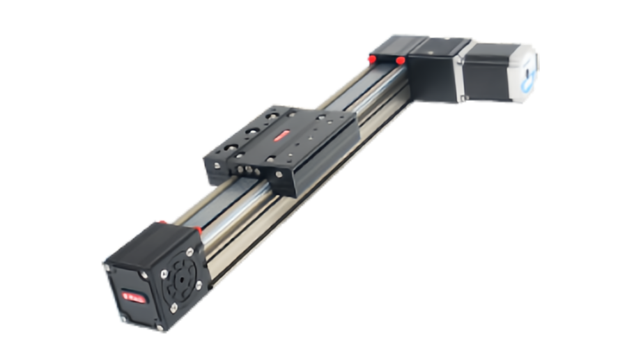
Timing beltlinear modulesare known for high-speed, long-stroke motion, but the maximum speed shown in a catalog is only one part of the real performance limit. In an operating machine, acceleration, belt tension, free belt length, pulley speed, carriage mass, guide stiffness, structural resonance and cable drag all influence how fast the axis can run reliably.
This is whytiming belt linear module speedshould be evaluated as a system condition rather than one isolated number. An axis may be mechanically capable of a high peak velocity but still suffer from belt whip, vibration, poor settling or excessive motor demand when the acceleration is too aggressive.
This guide explains the practical speed and acceleration limits of timing belt modules and shows how to diagnose and improve high-speed performance.
Maximum Speed Is Not the Same as Usable Production Speed
A manufacturer's maximum speed generally indicates the upper operating capability of a specific module under defined conditions.
The real production speed may need to be lower because of:
- Payload
- Acceleration requirement
- Stroke length
- Belt tension
- Motor torque at speed
- Guide and carriage dynamics
- Machine-frame stiffness
- Cable-carrier resistance
- Required settling time
Practical rule:a useful maximum speed is the highest speed the complete axis can repeat over the required duty cycle while maintaining positioning, vibration, temperature and service-life targets.
What Actually Limits Timing Belt Module Speed?
| Potential Limit | What Happens |
|---|---|
| Belt speed rating | The belt reaches its approved operating range |
| Pulley rpm | Bearings, shaft and pulley rotational limits are approached |
| Motor speed | Motor reaches rpm limit or loses available torque |
| Belt vibration | Free belt spans begin to oscillate |
| Guide dynamics | Carriage vibration, noise or heat increases |
| Machine structure | Frame or crossbeam resonance limits stable operation |
| Cable carrier | Drag and vibration rise with speed |
Linear Speed and Pulley Speed Are Directly Related
The carriage speed is determined by pulley rotational speed and pulley pitch circumference.
Conceptually:
v = ω × r
or, using pulley rotational speed:
v = π × D × n ÷ 60
where:
- v= linear speed in m/s
- D= pulley pitch diameter in m
- n= pulley speed in rpm
A larger pulley produces more linear travel per revolution, so the same carriage speed can be achieved at lower motor rpm.
Why a Larger Pulley Does Not Automatically Solve High-Speed Problems
A larger pulley reduces rotational speed for the same linear velocity, but it also increases the torque required for the same linear thrust.
For belt drive:
T = F × r ÷ h
This means pulley size creates a speed-torque trade-off:
- Larger pulley: lower rpm, higher torque demand
- Smaller pulley: higher rpm, lower torque demand
The smallest pulley is also limited by belt bending fatigue and minimum tooth-engagement requirements.
Acceleration Often Limits Real Cycle Time Before Maximum Speed Does
Many timing belt axes operate over short or medium strokes. The carriage may spend little or no time at maximum velocity before deceleration begins.
In this case, acceleration is more important than nominal top speed.
The acceleration force is:
Facc= m × a
where moving mass includes the carriage payload, fixtures, upper axes, moving cables and other attached equipment.
A simple example
A 12 kg moving assembly accelerated at 5 m/s2requires:
Facc= 12 × 5 = 60 N
This is before adding guide resistance, cable drag or process force.
Why High Acceleration Is Harder on the Belt
Higher acceleration increases belt tension difference between the driving and return sides.
This can lead to:
- Greater elastic belt stretch
- Higher tooth load
- More carriage vibration
- Higher pulley bearing load
- Higher motor torque demand
- More stress during reversal
Therefore, a module may reach a high steady speed safely but struggle when commanded to reach that speed too quickly.
Acceleration Limits Are Usually System Limits
There is rarely one universal acceleration limit for all timing belt modules.
The practical limit depends on:
- Moving mass
- Belt width and stiffness
- Belt pretension
- Pulley diameter
- Motor peak torque
- Guide preload
- Carriage geometry
- Frame stiffness
- Tooling overhang
The same module can therefore have very different acceleration capability under different payloads.
What Is Belt Whip?
Belt whipis visible or dynamic oscillation of a free belt span during high-speed motion, rapid acceleration or reversal.
It can appear as:
- Vertical belt flutter
- Lateral belt vibration
- Audible slapping or buzzing
- Periodic contact with covers
- Unstable motion after reversal
Belt whip is not only a noise problem. Severe oscillation can affect tooth engagement, positioning consistency and belt life.
What Causes Belt Whip?
Common causes include:
- Long unsupported belt spans
- Insufficient belt tension
- Very high belt speed
- Rapid acceleration and deceleration
- Excitation near a natural frequency
- Pulley misalignment
- Uneven belt tracking
Long stroke increases sensitivity
As free belt length increases, the belt can behave more like a flexible vibrating element. This is one reason long-stroke axes require more attention to tension and dynamic testing.
Belt Tension Strongly Influences High-Speed Stability
If tension is too low
Possible effects include:
- Belt whip
- Tooth jump
- Poor reversal repeatability
- Increased noise
If tension is too high
Possible effects include:
- Higher pulley-bearing load
- Higher motor torque demand
- Accelerated belt fatigue
- Increased structural load
High-speed tuning does not mean tightening the belt as much as possible.Use the specified pretension and confirm behavior dynamically.
Vibration Can Come From More Than the Belt
When a high-speed belt axis vibrates, the belt is only one possible source.
Other sources include:
- Flexible machine frames
- Long crossbeams
- Overhung tooling
- Cable carriers
- Loose motor mounts
- Guide preload
- Servo tuning
- Pulley or shaft runout
A mechanically flexible frame cannot be corrected completely by control tuning.
Structural Resonance Can Become the Real Speed Limit
Every mechanical structure has natural frequencies. If acceleration commands or periodic belt forces excite one of those frequencies, vibration can increase sharply.
This can affect:
- Settling time
- Position repeatability
- Noise
- Tool-path quality
- Fastener life
Wide gantries and long machine frames are especially sensitive because their first structural modes can occur at relatively low frequencies.
Settling Time Is Part of High-Speed Performance
A high-speed axis is not useful if the machine must wait a long time after every move.
Effective cycle time is:
Cycle time = acceleration + travel + deceleration + settling + process time
If higher acceleration reduces travel time by 50 ms but adds 100 ms of vibration settling, the machine becomes slower overall.
Short-Stroke and Long-Stroke Axes Behave Differently
| Axis Type | Typical Dynamic Focus |
|---|---|
| Short stroke | Acceleration, deceleration, reversal, settling |
| Medium stroke | Balance of acceleration and maximum speed |
| Long stroke | Belt speed, whip, stiffness, cable dynamics and support |
This is why one catalog maximum speed cannot describe every application equally well.
High-Speed Pick-and-Place Applications
Pick-and-place equipment often uses timing belt modules because of low moving mass and fast reversing capability.
The key design variables are:
- Short move distance
- High acceleration
- Low tooling mass
- Fast settling
- High reversal count
For this type of application, acceleration and stiffness often matter more than ultimate top speed.
Long-Travel Transfer Applications
Long conveyor-side transfer, gantry systems and material-handling axes may spend more time at constant velocity.
Important checks include:
- Belt speed rating
- Pulley rpm
- Motor continuous-speed capability
- Belt vibration
- Cable-carrier stability
- Long-beam support
High-Speed Printing and Scanning
Printing, coating and inspection applications may require the carriage to move at stable velocity through a process zone.
For these applications, speed quality matters as much as speed magnitude.
Check:
- Velocity ripple
- Servo following error
- Belt elasticity
- Guide straightness
- Structural vibration
Motor Torque Falls With Speed
Motor capability must be checked at the actual rpm required by the pulley.
This is especially important for stepper motors, whose available torque usually decreases significantly as speed rises.
Servo systems also have continuous and peak torque limits and a finite maximum speed.
High-speed sizing should therefore use:
- Required pulley rpm
- Motor torque-speed curve
- Peak torque during acceleration
- RMS torque over the cycle
- Drive voltage and current limits
Motor Power Alone Does Not Define Maximum Speed
A motor with more watts does not automatically make the axis faster.
Maximum speed may still be limited by:
- Motor rpm
- Pulley size
- Belt speed rating
- Guide dynamics
- Structural resonance
- Cable carrier
Belt Width and Stiffness Influence Acceleration
A wider or stiffer belt can reduce elastic elongation under dynamic force.
This can improve:
- Reversal behavior
- Settling
- Dynamic positioning
- Control stability
But increasing belt width also increases pulley width and can affect cost, alignment and module size.
Pulley Diameter Must Balance Speed, Torque and Belt Life
Pulley selection should satisfy all of the following:
- Required linear speed
- Motor rpm capability
- Required thrust
- Minimum belt bending radius
- Required engaged teeth
- Bearing limits
There is no single pulley diameter that maximizes every performance metric.
Guide Preload and Running Resistance
Higher guide preload can improve stiffness, but it also increases rolling resistance and heat.
At high speed, excessive preload may increase:
- Motor demand
- Guide temperature
- Wear
The guide should be selected for the required stiffness and load rather than using the highest available preload automatically.
Cable Carriers Can Become a Major Dynamic Load
At low speed, cable drag may seem insignificant. At high speed and acceleration, the cable carrier can become a major source of force and vibration.
Check:
- Carrier mass
- Bend radius
- Maximum travel speed
- Maximum acceleration
- Unsupported span
- Cable fill and arrangement
The fastest linear module in the machine can still be limited by the cable system attached to it.
How Motion Profiles Affect Vibration
An abrupt trapezoidal velocity profile can excite more vibration than a smoother profile.
S-curve or jerk-limited motion can reduce the rate of change of acceleration and help decrease:
- Frame excitation
- Belt vibration
- Tool oscillation
- Settling time
The best profile depends on cycle time and process sensitivity.
How to Increase High-Speed Stability
1. Reduce moving mass
Use lightweight tooling, compact brackets and optimized cable routing.
2. Use correct belt tension
Maintain the specified pretension rather than tightening by feel.
3. Increase structural stiffness
Strengthen bases, crossbeams and tooling supports.
4. Use an appropriate belt width and tensile stiffness
This reduces elastic response under acceleration.
5. Select pulley size as a system variable
Balance motor rpm, thrust, tooth engagement and bending life.
6. Improve motor and servo matching
Check torque-speed performance and inertia rather than motor power alone.
7. Optimize the motion profile
Use jerk control or smoother acceleration where vibration is limiting productivity.
8. Improve cable management
Reduce drag variation and avoid cable-carrier resonance.
9. Test at full stroke and real load
Long-belt behavior may not appear during short-stroke bench testing.
Signs That the Axis Is Being Run Too Aggressively
- Visible belt flutter or whip
- Repeated tooth-jump events
- Increasing motor current
- Servo following alarms
- Longer settling time
- New vibration or resonance
- Belt-edge wear
- Pulley-bearing noise
- Guide temperature rise
- Positioning repeatability becomes load-dependent
These symptoms should be investigated before increasing speed further.
How to Determine a Practical Maximum Speed
- Confirm the module manufacturer's speed rating.
- Calculate pulley rpm at the target linear speed.
- Check motor torque and rpm at that operating point.
- Check belt speed and pulley limits.
- Check cable-carrier speed and acceleration limits.
- Run the axis with the real moving mass.
- Test the full stroke.
- Measure vibration, settling and motor demand.
- Repeat over the real duty cycle.
- Set the production limit below the onset of unstable behavior.
How to Determine a Practical Acceleration Limit
- Calculate the required acceleration force.
- Check motor peak torque.
- Check belt tooth and tensile capacity.
- Check pulley and bearing loads.
- Evaluate belt stretch and positioning.
- Measure vibration and settling.
- Check guide and structure stiffness.
- Confirm repeated performance over the duty cycle.
What QRXQ Needs to Evaluate High-Speed Belt Motion
- Required stroke
- Moving mass
- Target maximum speed
- Target acceleration
- Cycle time
- Reversal frequency
- Belt profile and width
- Pulley tooth count or pitch diameter
- Motor model
- Horizontal, vertical or gantry installation
- Required repeatability
- Cable-carrier configuration
The real high-speed limit of a timing belt module is a system limit.Belt speed, motor rpm, acceleration force, vibration, structure and cable dynamics must all remain inside a stable operating window.
QRXQ evaluates timingbelt linear modulespeed and acceleration from the complete motion profile rather than relying only on the highest velocity shown in a catalog.
