 English

Atiming belt linear moduleis widely used in industrial automation systems that require high-speed movement, long travel distances and frequent reciprocating motion. Its main components usually include a timing belt, drive pulley, idler pulley, linear guide, carriage, motor, sensors and belt tensioning mechanism.
Althoughtiming belt linear moduleshave a relatively simple mechanical structure, improper installation, incorrect belt tension, component wear, insufficient lubrication or control-system faults can cause positioning errors, abnormal noise, vibration, belt slippage and motor alarms.
Effectivetiming belt linear module troubleshootingshould not focus only on the visible symptom. Engineers must systematically inspect the mechanical transmission system, guide system, motor, sensors, electrical connections and control parameters to determine the actual cause of the problem.
This guide explains the most common timing belt module problems, their possible causes, recommended inspection methods and practical repair solutions.
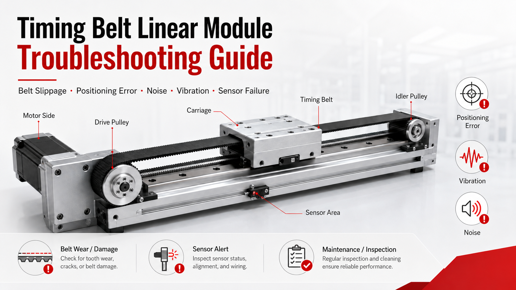
Common Timing Belt Linear Module Problems
The most frequently reported problems include:
- Timing belt slippage or tooth skipping
- Increasing positioning error
- Poor repeatability
- Abnormal mechanical noise
- Vibration during acceleration or deceleration
- Timing belt wear or damage
- Pulley wear or misalignment
- Motor overload or servo alarm
- Limit switch or sensor failure
- Carriage movement that is rough or unstable
Some symptoms may be caused by more than one component. For example, positioning errors may result from belt slippage, loose pulley connections, incorrect motor parameters, excessive load, sensor failure or structural deformation. A complete inspection is therefore more reliable than replacing individual components based only on the visible symptom.
Recommended Troubleshooting Workflow
Before disassembling the timing belt linear module, follow a structured troubleshooting workflow.
- Record the operating conditions when the fault occurs.
- Check the controller, servo drive or stepper drive alarm code.
- Inspect the timing belt, pulleys, carriage and guide rail visually.
- Manually move the carriage after safely disconnecting the drive system.
- Check belt tension and pulley alignment.
- Verify motor coupling, pulley locking and mounting bolts.
- Inspect sensors, cables and electrical connectors.
- Review motion parameters such as speed, acceleration and deceleration.
- Run the module at low speed without load.
- Gradually restore the normal load and operating speed.
This procedure helps separate mechanical problems from electrical and control problems. It also prevents unnecessary replacement of functional components.
Safety Precautions Before Troubleshooting
Before inspecting or repairing the linear module, stop the equipment and disconnect the main power supply. Release any suspended load and make sure the carriage cannot move unexpectedly.
Do not touch the timing belt, pulley or carriage while the system is operating. Stored mechanical energy, motor holding torque and external loads may cause sudden movement even after the machine has stopped.
After maintenance, reinstall all protective covers and confirm that tools, fasteners and foreign objects have been removed from the motion area.
Timing Belt Slippage or Tooth Skipping
Timing belt slippage is one of the most common faults in belt drivenlinear modules. Because the belt uses toothed engagement with the pulleys, the problem often appears as tooth skipping rather than continuous friction-based slipping.
Typical Symptoms
- The carriage does not reach the commanded position.
- A sudden knocking sound occurs during acceleration.
- The positioning error appears after high-speed movement.
- The motor rotates, but the carriage movement is reduced or interrupted.
- The home position changes after repeated cycles.
Possible Causes
- Insufficient timing belt tension
- Excessive acceleration or deceleration
- Load exceeding the module capacity
- Contamination on the belt or pulley teeth
- Damaged or worn belt teeth
- Worn pulley teeth
- Loose drive pulley or locking element
- Incorrect belt specification
Recommended Solutions
Check the belt tension according to the module manufacturer's adjustment requirements. A belt that is too loose can skip teeth during acceleration, while excessive tension can overload bearings, increase friction and shorten belt life.
Inspect the full belt length for damaged teeth, cracks, exposed tensile cords, polished surfaces or uneven wear. Replace the belt if structural damage is found.
Clean the pulley teeth and remove oil, dust, metal chips or other contaminants. Verify that the drive pulley is securely locked to the motor shaft and that the idler pulley rotates normally.
If the mechanical components are in good condition, reduce acceleration and deceleration settings and test the module again. A motion profile that is too aggressive can generate peak forces that exceed the belt's transmission capacity.
Positioning Error and Poor Repeatability
Positioning accuracy describes how closely the carriage reaches the commanded position. Repeatability describes how consistently it returns to the same position during repeated movements.
A timing belt linear module is normally selected for high speed and long stroke rather than ultra-high absolute accuracy. However, a sudden increase in positioning error usually indicates a mechanical, control or feedback problem.
Possible Causes
- Belt tooth skipping
- Loose drive pulley
- Incorrect belt tension
- Excessive belt elongation
- Loose carriage or mounting bolts
- Overloaded carriage
- Insufficient structural rigidity
- Incorrect motor pulse or electronic gearing settings
- Servo tuning problems
- Home sensor position changes
- Encoder or feedback signal faults
Inspection Method
Use a dial indicator, laser measurement system or other suitable measuring device to compare the commanded movement with the actual carriage movement. Repeat the same motion several times to determine whether the error is consistent or random.
A consistent proportional error may indicate an incorrect pulse equivalent, pulley diameter setting or electronic gearing ratio. Random errors are more likely to be caused by belt skipping, loose components, sensor instability or electrical interference.
Recommended Solutions
Tighten the motor mount, pulley locking elements, carriage bolts and module mounting bolts. Check whether the base structure is flat and sufficiently rigid.
Verify the controller's travel calibration, pulse settings, encoder resolution and electronic gear ratio. For servo-driven systems, inspect the following error and review the servo tuning parameters.
If the positioning deviation increases with travel distance, inspect the belt for permanent elongation and confirm that the correct pulley circumference and transmission ratio are configured.
Abnormal Noise During Operation
A correctly installed timing belt linear module should operate with a relatively smooth and consistent sound. New knocking, grinding, squealing or clicking noises should be investigated as soon as possible.
Common Noise Types and Possible Causes
| Noise Type | Possible Cause |
|---|---|
| Rhythmic clicking | Damaged belt teeth, pulley damage or belt tooth skipping |
| High-frequency squealing | Excessive belt tension, bearing friction or belt misalignment |
| Grinding noise | Guide rail damage, bearing failure or foreign objects |
| Knocking during acceleration | Loose pulley, loose motor mount or excessive acceleration |
| Irregular rattling | Loose fasteners, cable carrier interference or cover vibration |
Recommended Solutions
Run the module at a low speed and identify where the sound is strongest. Inspect the timing belt, pulleys, bearings, guide blocks, protective cover and cable carrier separately.
Check whether the belt runs in the center of the pulley and whether both pulleys are aligned. Belt edge contact with the pulley flange can produce continuous rubbing noise and edge wear.
Inspect the guide rail for contamination or insufficient lubrication. If the noise continues after cleaning, tension adjustment and lubrication, inspect the pulley bearings and guide blocks for internal damage.
Vibration During Movement
Vibration may reduce positioning stability, increase mechanical wear and affect nearby processes such as vision inspection, dispensing, laser processing or precision assembly.
Possible Causes
- Acceleration and deceleration are too high.
- The moving load has a high center of gravity.
- The module base is not rigid enough.
- Mounting bolts are loose.
- Belt tension is incorrect.
- The timing belt is unevenly worn.
- The pulleys are misaligned.
- Servo gain is too high.
- The mechanical system is operating near its resonance frequency.
- The carriage is subjected to excessive moment load.
Recommended Solutions
Reduce the acceleration, deceleration and jerk settings to determine whether the vibration is related to the motion profile. If vibration decreases significantly, optimize the motion curve rather than simply limiting the maximum speed.
Check the module base, support frame and mounting surface. Long-stroke modules may require additional support points to prevent profile deflection.
Reduce the distance between the load center of gravity and the carriage whenever possible. A tall or offset load creates additional pitch, yaw and roll moments on the guide system.
For servo systems, review the gain, filter and resonance suppression settings. Mechanical adjustments should be completed before control parameters are used to compensate for excessive looseness or structural instability.
Timing Belt Wear and Damage
The timing belt is a wear component. Its service life depends on load, speed, acceleration, tension, pulley diameter, operating environment and duty cycle.
Common Wear Patterns
- Cracks on the belt surface
- Missing or damaged teeth
- Frayed belt edges
- Exposed tensile cords
- Polished or hardened tooth surfaces
- Uneven belt width
- Oil contamination or chemical damage
Wear Pattern Diagnosis
Edge wear usually indicates pulley misalignment, belt tracking problems or contact with surrounding structures. Tooth damage may result from overload, tooth skipping or foreign objects entering the pulley.
Cracks across the belt surface may be caused by aging, unsuitable pulley diameter, extreme temperature or chemical exposure. Exposed tensile cords indicate serious structural damage and require immediate belt replacement.
Recommended Solutions
Replace the timing belt with the specified model, tooth profile, width and length. Do not mix belts and pulleys with incompatible tooth profiles.
After replacing the belt, check pulley alignment and adjust the tension correctly. Replacing the belt without correcting the original cause may result in rapid repeat failure.
Pulley Wear or Misalignment
The drive pulley and idler pulley directly affect belt engagement, transmission accuracy and belt service life.
Possible Symptoms
- Uneven belt edge wear
- Repeated belt tracking toward one side
- Periodic noise during each pulley rotation
- Increasing backlash or positioning error
- Metal dust near the pulley
- Visible pulley tooth wear
Inspection and Repair
Inspect the pulley tooth profile, flange, shaft connection and bearing condition. Rotate the pulley manually and check for resistance, radial movement or abnormal sound.
Verify that the pulley shafts are parallel and that the pulley faces are correctly aligned. Check the locking screws, key connection, clamping hub or other shaft-locking components.
A severely worn pulley should be replaced together with the belt if the damaged tooth profile may have affected belt engagement.
Motor Alarm or Motor Overload
A motor alarm does not always mean that the motor itself is damaged. Mechanical resistance, incorrect parameters or wiring problems can also trigger overload, overcurrent, following-error or encoder alarms.
Possible Causes
- Carriage or guide system is mechanically blocked.
- Belt tension is too high.
- Load exceeds the motor or module capacity.
- Acceleration is too high.
- Pulley or bearing is damaged.
- Motor power cable is loose.
- Encoder cable is damaged or affected by interference.
- Servo parameters are incorrect.
- Brake is not fully released.
- Motor temperature is too high.
Troubleshooting Method
Record the alarm code before resetting the drive. Check the drive manual to identify whether the alarm relates to current, encoder feedback, following error, temperature, voltage or communication.
Disconnect the motor from the mechanical transmission system when appropriate and test the motor separately. Manually move the carriage to determine whether abnormal mechanical resistance exists.
If the motor operates normally without the load, inspect the module, transmission system and load configuration. If the alarm remains, inspect the motor cables, encoder cables, drive settings and power supply.
Sensor and Limit Switch Failure
Timing belt linear modules commonly use home sensors, positive limit sensors and negative limit sensors to establish machine coordinates and prevent overtravel.
Typical Symptoms
- The module cannot complete the homing process.
- The carriage moves in the wrong direction during homing.
- The controller continuously reports a limit alarm.
- The sensor indicator does not change when the carriage passes.
- The home position changes between cycles.
- The carriage travels beyond the expected stopping position.
Possible Causes
- Incorrect sensor mounting position
- Sensor target is too far away
- Loose sensor bracket
- Damaged sensor cable
- Incorrect wiring polarity
- Incompatible NPN or PNP signal
- Incorrect controller input configuration
- Metal chips, dust or oil affecting the sensor
- Electrical interference
Recommended Solutions
Check the sensor indicator and measure the output signal while moving the carriage slowly through the sensing area. Verify the sensor supply voltage, signal type and controller input configuration.
Clean the sensor and target, adjust the sensing distance and tighten the mounting bracket. Route sensor cables separately from high-power motor cables whenever possible.
After replacing or repositioning the home sensor, repeat the homing procedure and verify the machine coordinate system before returning the equipment to production.
Carriage Movement Is Rough or Uneven
Rough carriage movement usually indicates problems in the linear guide system, belt alignment, pulley bearings or mounting structure.
Possible Causes
- Insufficient guide rail lubrication
- Dust or metal particles on the guide rail
- Damaged guide block
- Deformed module profile
- Uneven mounting surface
- Incorrect belt tension
- Pulley bearing damage
- External cable or hose resistance
Recommended Solutions
Remove the load and move the carriage manually at low speed. Inspect whether resistance appears at a specific position or throughout the entire travel.
Clean and lubricate the guide rail using the recommended lubricant. Check the mounting surface for flatness and verify that the module has not been twisted during installation.
Inspect cables, pneumatic hoses and cable carriers to confirm that they do not pull or push the carriage unevenly.
Troubleshooting Reference Table
| Problem | Likely Cause | Recommended Action |
|---|---|---|
| Position is lost after acceleration | Belt tooth skipping or loose pulley | Adjust belt tension, inspect teeth and tighten the pulley |
| Repeated positioning error | Incorrect pulse setting or belt elongation | Check calibration, transmission ratio and belt condition |
| High-frequency noise | Excessive tension or pulley misalignment | Readjust belt tension and pulley alignment |
| Vibration at high speed | Excessive acceleration or low structural rigidity | Optimize motion parameters and reinforce the support structure |
| Motor overload alarm | Mechanical resistance, overload or incorrect parameters | Check carriage resistance, load and motor settings |
| Homing failure | Sensor, wiring or configuration fault | Check sensor output, wiring and controller input settings |
| Belt edge wear | Pulley misalignment or belt tracking problem | Align the pulleys and inspect surrounding clearance |
| Grinding during movement | Guide block or bearing damage | Inspect lubrication, guide blocks and pulley bearings |
Preventive Maintenance Recommendations
Preventive maintenance reduces unexpected downtime and helps maintain stable positioning performance.
- Inspect the timing belt regularly for cracks, edge wear and damaged teeth.
- Check belt tension after initial operation and during scheduled maintenance.
- Confirm that the drive pulley remains securely locked.
- Clean the guide rail, pulley area and protective cover.
- Lubricate the linear guide according to operating conditions.
- Check motor, sensor and encoder cables for bending or damage.
- Inspect module mounting bolts and load mounting bolts.
- Record positioning accuracy and motor load trends.
- Prevent oil, coolant, metal chips and chemicals from contacting the belt.
- Review speed and acceleration settings after changing the payload.
Maintenance intervals should be adjusted according to operating speed, travel distance, load, environmental contamination and daily operating hours. Equipment operating continuously in dusty or high-cycle environments usually requires more frequent inspection.
When Should the Timing Belt Be Replaced?
The timing belt should be replaced when missing teeth, exposed tensile cords, severe cracks, permanent deformation or significant edge damage are found.
Replacement should also be considered when positioning performance continues to deteriorate after proper tension adjustment, or when the belt has reached the recommended maintenance interval for the application.
After belt replacement, verify the belt tension, pulley alignment, home position, travel limits and positioning calibration before normal production resumes.
When Should Professional Repair Be Considered?
Professional inspection is recommended when the module has experienced a collision, severe overload, repeated motor alarms, structural deformation or unexplained positioning instability.
It may also be necessary when replacing internal guide blocks, pulley bearings, motor components or feedback devices requires specialized tools and alignment procedures.
Continuing to operate a damaged module may cause additional belt, pulley, guide and motor damage, increasing both repair cost and equipment downtime.
Frequently Asked Questions
Why does a timing belt linear module lose position?
Common causes include belt tooth skipping, loose pulleys, incorrect belt tension, incorrect pulse settings, excessive acceleration, sensor instability and motor feedback errors.
How can timing belt slippage be prevented?
Use the correct belt specification, maintain proper belt tension, keep the pulley teeth clean, avoid excessive acceleration and ensure that the payload remains within the module's rated capacity.
Why does the module make noise only at high speed?
High-speed noise may be caused by belt vibration, excessive tension, pulley misalignment, bearing wear, structural resonance or cable carrier interference.
Can excessive belt tension improve positioning accuracy?
No. Excessive tension may reduce visible belt looseness, but it also increases bearing load, motor resistance and belt wear. Belt tension should remain within the specified range.
Why does the motor alarm after the load is increased?
The increased payload may exceed the motor torque, belt transmission capacity or guide moment capacity. Acceleration may also be too high for the new load.
Should the belt and pulley be replaced together?
If the pulley teeth are worn, damaged or no longer match the belt profile correctly, replacing both components is recommended. A damaged pulley can rapidly wear a new belt.
Conclusion
Reliabletiming belt linear module troubleshootingrequires a systematic inspection of the belt, pulleys, guide system, motor, sensors, wiring and control parameters.
Belt slippage, positioning errors, abnormal noise and vibration are often related to incorrect belt tension, loose components, excessive acceleration, pulley misalignment or mechanical wear. Motor alarms and homing failures may involve both mechanical resistance and electrical signal problems.
By recording symptoms, inspecting components in a logical sequence and testing the module at low speed before restoring normal operation, engineers can identify faults more accurately and reduce unnecessary replacement of parts.
Regular belt inspection, guide lubrication, pulley alignment checks and motion-parameter review can significantly reduce unexpected failures and maintain stable performance throughout the service life of the timing belt linear module.
