 English

Horizontal installation is one of the most common configurations for a timingbelt linear module. It is widely used in automated loading, material transfer, packaging, inspection, dispensing, sorting and pick-and-place systems.
Although a horizontal axis is not required to lift the payload directly against gravity, installation quality still has a major influence on positioning accuracy, guide service life, operating noise and motion stability. The mounting surface, payload position, structural support, moment load, acceleration and cable routing must all be considered before the module is put into operation.
This guide explains the main requirements for installing a timing belt linear module horizontally and provides a practical inspection checklist for machine builders and automation engineers.
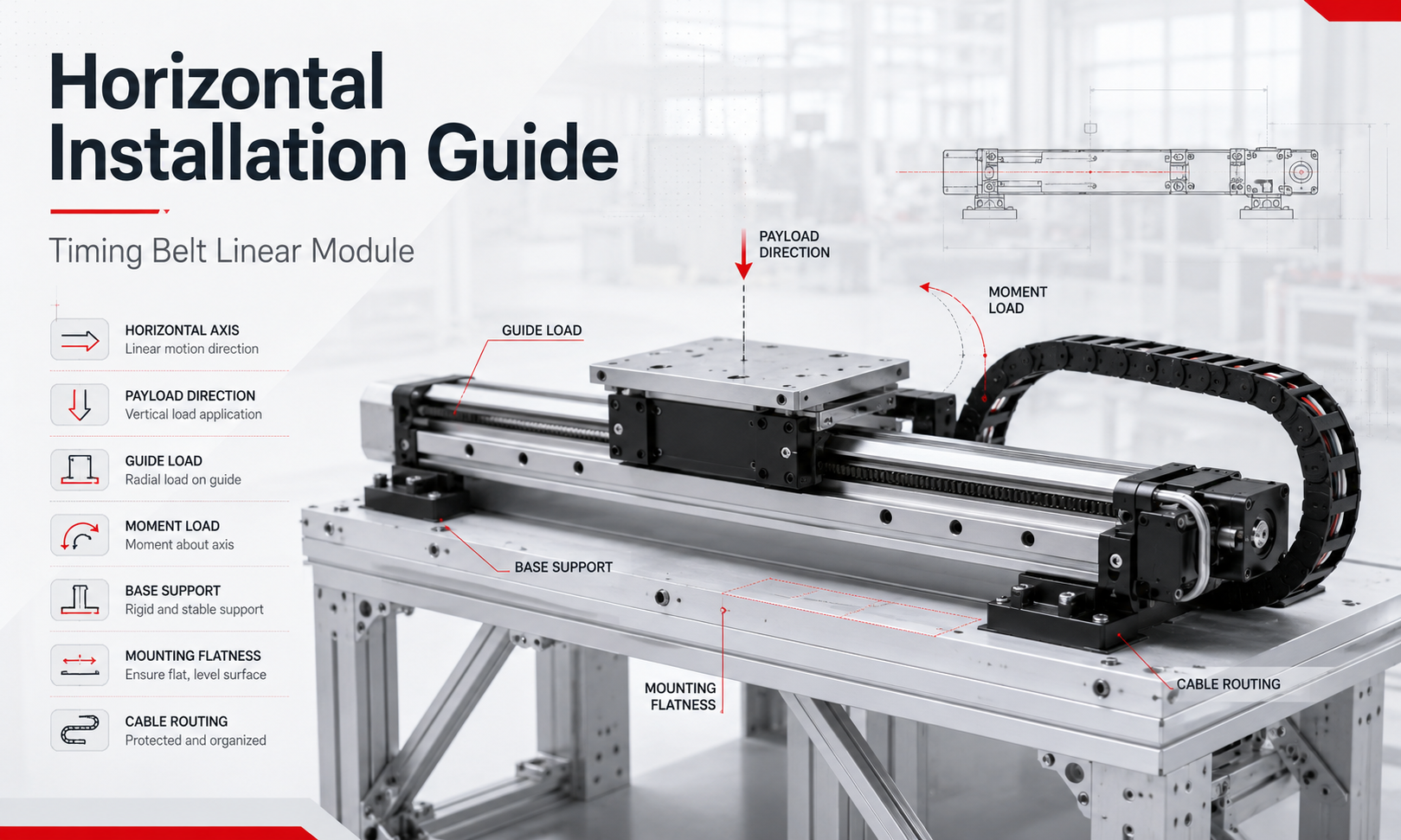
What Is Horizontal Installation?
Horizontal installation means that the main travel direction of the timing belt linear module is parallel or approximately parallel to the ground. The carriage moves along the horizontal axis while the guide system supports the weight of the payload.
In this configuration, the motor mainly provides the force required to overcome:
- Payload acceleration and deceleration
- Friction in the guide and transmission system
- External process forces
- Cable drag chain resistance
- Additional resistance caused by misalignment
The payload does not normally create a continuous gravitational force in the direction of travel. However, its weight acts vertically on the guide rail and may create significant pitch, yaw or roll moments when the center of gravity is offset from the carriage.
Typical Horizontal Axis Configurations
A timing belt linear module can be installed horizontally in several structural arrangements.
Single Horizontal Axis
A single module is mounted on a machine frame and moves a fixture, sensor, gripper or lightweight workpiece along one direction. This is the simplest horizontal configuration.
Parallel Dual-Axis System
Two timing belt modules are installed in parallel to support a wide platform or large workpiece. The two axes may be mechanically connected or electronically synchronized.
Parallel installation is commonly used when:
- The platform is wider than one carriage
- The payload has a large center-of-gravity offset
- High resistance to roll moment is required
- The structure must remain stable over a long stroke
Horizontal Axis in a Multi-Axis System
The timing belt module may also serve as the X-axis or Y-axis of an XY, XZ or XYZ motion system. In this arrangement, the horizontal module may carry another linear axis, motor, end effector and workpiece at the same time.
The total moving mass must include every component mounted on the carriage, not only the final payload.
Determine the Payload Direction
Before selecting or installing the module, identify how the payload force acts on the carriage and guide system.
| Load Condition | Description | Main Design Concern |
|---|---|---|
| Centered vertical load | The payload center of gravity is close to the center of the carriage. | Guide load capacity and dynamic load |
| Offset vertical load | The payload center of gravity is positioned away from the carriage center. | Pitch and roll moments |
| Side-mounted load | The module or payload is mounted on its side. | Guide orientation and yaw moment |
| Cantilevered load | The payload extends beyond the carriage. | Moment load and structural deflection |
| External process load | The carriage is exposed to pressing, cutting, dispensing or contact forces. | Combined static and dynamic forces |
A payload that is within the rated mass limit may still overload the guide if its center of gravity is too far from the carriage. Payload mass and moment load must therefore be evaluated together.
Guide Load and Moment Load
The linear guide supports the payload and controls the orientation of the carriage. During horizontal operation, the guide may be exposed to vertical force, lateral force and rotational moments.
The three principal moment directions are:
- Pitch moment:rotation around the lateral axis
- Yaw moment:rotation around the vertical axis
- Roll moment:rotation around the travel axis
A simplified moment calculation is:
M = F × L
Where:
- Mis the moment load
- Fis the applied force
- Lis the distance between the force and the guide or carriage reference point
For example, a 20 kg payload produces an approximate gravitational force of:
F = 20 × 9.81 = 196.2 N
If the payload center of gravity is located 0.15 m from the carriage center, the approximate moment is:
M = 196.2 × 0.15 = 29.43 N·m
The calculated value should be compared with the permissible static and dynamic moment ratings of the selected module. A suitable safety factor should also be applied for acceleration, vibration, impact and uncertain load conditions.
Include Acceleration Force in the Load Calculation
Horizontal movement eliminates the need to continuously lift the payload, but acceleration still creates an inertial force in the travel direction.
The basic relationship is:
Fa= m × a
Where:
- Fais the acceleration force
- mis the total moving mass
- ais the acceleration
The total moving mass should include:
- Workpiece
- Fixture
- Carriage-mounted plate
- Gripper or tooling
- Secondary linear axis
- Motor and reducer mounted on the moving structure
- Moving cables and cable carrier components
High acceleration increases belt tension, motor torque demand, guide loading and structural vibration. For applications with rapid start-stop cycles, the module should not be selected based only on maximum payload capacity.
Provide Adequate Base Support
The aluminum profile of a timing belt linear module is designed to provide stiffness, but it should not automatically be treated as a self-supporting structural beam over every stroke length.
Insufficient support may cause:
- Base profile deflection
- Guide misalignment
- Uneven belt tension
- Carriage vibration
- Increased running noise
- Reduced positioning accuracy
- Premature guide or bearing wear
The module should be mounted on a rigid machine frame, machined plate or properly supported aluminum structure. Long-stroke modules may require continuous support or multiple support points along the base.
Support spacing depends on the module profile, stroke, payload, acceleration and required accuracy. For long or heavily loaded axes, the allowable profile deflection should be checked rather than relying only on the nominal load rating.
Mounting Surface Flatness
The mounting surface must be sufficiently flat to prevent the module base from twisting or bending when the mounting bolts are tightened.
A poor mounting surface can force the guide rail out of alignment and increase internal resistance. Common symptoms include:
- Uneven carriage resistance
- Abnormal noise at certain positions
- Higher motor current
- Vibration during acceleration
- Reduced repeatability
- Premature guide wear
The acceptable flatness depends on the module size, guide design, stroke and accuracy requirement. The module supplier’s installation tolerance should be used whenever available.
For precision systems, inspect the mounting surface using suitable instruments such as:
- Precision straightedge
- Dial indicator
- Electronic level
- Laser alignment system
- Coordinate measuring equipment
Clean the Mounting Surface Before Installation
Before positioning the module, clean both the machine base and the underside of the module. Remove:
- Metal chips
- Dust and abrasive particles
- Oil residue
- Paint buildup
- Burrs around threaded holes
- Raised edges caused by machining damage
Even a small chip trapped under the base can create local deformation when the mounting bolts are tightened.
Align the Module Before Final Tightening
Do not fully tighten all mounting bolts immediately after placing the module on the machine frame.
A recommended installation sequence is:
- Clean and inspect the mounting surface.
- Position the module on the machine base.
- Install the mounting bolts loosely.
- Align the module using a reference edge, locating pins or measuring equipment.
- Move the carriage through the full stroke and check for abnormal resistance.
- Tighten the bolts gradually in a balanced sequence.
- Recheck straightness, parallelism and running resistance.
Uneven tightening may twist the module base. Use the specified bolt grade and tightening torque, and avoid excessive force that could deform the aluminum profile.
Parallelism in Dual-Module Installations
When two timing belt modules are installed in parallel, their travel paths must remain parallel over the full stroke.
Poor parallelism can cause:
- Cross-loading between the two guides
- Platform binding
- Unequal motor load
- Synchronization errors
- Increased belt and bearing wear
- Loss of positioning accuracy
One axis is normally used as the primary alignment reference. The second axis should be adjusted relative to the first before the connecting platform is fully tightened.
For wide platforms, avoid over-constraining the structure. A rigid connection between two imperfectly aligned axes can transfer large internal forces into the guide blocks.
Check Pulley and Belt Alignment
Although the belt transmission is normally adjusted during module assembly, installation errors can still affect belt operation, especially when external components are added to the drive end.
Check that:
- The motor and coupling are correctly installed
- The drive pulley rotates without visible wobble
- The belt remains centered during full-stroke movement
- The carriage does not create abnormal belt noise
- No external bracket interferes with the belt or end cover
Do not change the factory belt tension unless adjustment is necessary and the correct procedure is available. Excessive belt tension increases bearing load and friction, while insufficient tension can cause vibration, backlash or tooth skipping.
Carriage Plate and Payload Installation
The payload mounting plate should be rigid enough to distribute the load over the carriage without bending.
When attaching the payload:
- Use the specified mounting holes
- Avoid drilling into the carriage without approval
- Keep the center of gravity close to the carriage center
- Use locating pins where repeatable assembly is required
- Prevent bolts from extending into internal moving parts
- Confirm that the fixture does not contact the module cover
A thin or flexible adapter plate may deform under load and reduce the effective stiffness of the complete motion system.
Cable and Drag Chain Routing
Cables, air tubes and sensor wires must be routed so that they do not interfere with carriage movement.
Good cable routing should:
- Maintain the specified minimum bending radius
- Prevent cables from rubbing against sharp edges
- Provide sufficient length for the full stroke
- Avoid excessive pulling force on connectors
- Separate power cables from sensitive signal cables when necessary
- Prevent the cable carrier from colliding with the module
- Keep cable carrier resistance as low and consistent as possible
The moving cable carrier creates an additional variable load. On long or high-speed axes, its mass and drag resistance should be included in the motor and payload calculations.
Sensor and Limit Switch Installation
Horizontal timing belt modules commonly use home sensors, positive limit sensors and negative limit sensors.
Before commissioning:
- Confirm the home sensor position
- Check the sensing distance
- Secure the sensor cable
- Verify the controller input signal
- Set software travel limits
- Confirm that the mechanical end position is not reached during normal operation
Software limits should be set inside the usable mechanical stroke so that the carriage has sufficient deceleration distance.
Motor and Brake Requirements
A brake motor is generally not required for a purely horizontal axis because gravity does not normally drive the carriage along the travel direction after power is removed.
However, a brake or mechanical locking device may still be considered when:
- The axis is installed on an inclined surface
- External forces can move the carriage after power-off
- The application requires position holding for safety
- The machine is installed on moving equipment
- Unexpected carriage movement could damage tooling or workpieces
The motor must be selected according to acceleration torque, operating speed, transmission efficiency, external resistance and duty cycle.
Initial Commissioning Procedure
After mechanical installation, perform the initial test at low speed and low acceleration.
- Move the carriage manually if the design permits.
- Check the full stroke for interference.
- Confirm sensor operation.
- Jog the axis at low speed.
- Listen for abnormal belt, guide or bearing noise.
- Monitor motor current and following error.
- Gradually increase speed and acceleration.
- Run repeated cycles under the actual payload.
- Recheck mounting bolts after the initial running period.
Do not begin commissioning at the maximum rated speed. A low-speed test makes it easier to detect misalignment, cable interference and incorrectly positioned sensors.
Horizontal Installation Checklist
| Inspection Item | Requirement |
|---|---|
| Mounting surface | Clean, rigid and within the required flatness tolerance |
| Base support | Adequate for the module length, payload and acceleration |
| Module alignment | Straight and correctly positioned relative to the machine reference |
| Mounting bolts | Correct grade, length and tightening torque |
| Payload center of gravity | As close as practical to the carriage center |
| Moment load | Within permissible pitch, yaw and roll ratings |
| Total moving mass | Includes fixture, tooling, secondary axes and cables |
| Carriage movement | Smooth over the complete stroke without binding |
| Cable routing | No pulling, rubbing, excessive bending or interference |
| Sensors | Secure, correctly positioned and electrically verified |
| Software limits | Set within the usable mechanical travel |
| Test operation | Completed progressively from low speed to normal conditions |
Common Horizontal Installation Mistakes
Mounting the Module on an Uneven Frame
An uneven frame can twist the module base and create excessive guide resistance. The frame should be inspected and corrected before final installation.
Ignoring the Payload Center of Gravity
Checking only the payload mass may lead to excessive moment loading. The center-of-gravity offset must be included in the calculation.
Supporting Only the Two Ends of a Long Module
A long module may deflect between the supports. Additional support points or continuous support may be required.
Using Excessive Bolt Tightening Torque
Overtightening may deform the aluminum base or damage the mounting threads. Follow the specified tightening torque.
Running at Full Speed During the First Test
High-speed commissioning can turn a minor alignment or cable-routing problem into serious mechanical damage.
Ignoring Cable Carrier Resistance
A large cable carrier can add significant moving mass and drag force, especially over a long stroke.
Frequently Asked Questions
Can a timing belt linear module be installed horizontally?
Yes. Horizontal installation is one of the standard mounting configurations for timing belt linear modules. The mounting surface, base support, payload position, guide load and acceleration must be checked carefully.
Does a horizontal timing belt module require a brake motor?
A brake is usually not required for a completely horizontal axis. It may be necessary when the axis is inclined, exposed to external forces or required to hold position for safety after power-off.
Why does the carriage become difficult to move after installation?
Possible causes include an uneven mounting surface, excessive bolt torque, base deformation, poor parallelism, cable interference or an incorrectly installed payload plate.
Can the module be supported only at both ends?
This depends on the module profile, unsupported length, payload and acceleration. Long-stroke modules may require intermediate or continuous support to control deflection.
How can moment load be reduced?
Move the payload center of gravity closer to the carriage, use a wider carriage, add a second parallel module, reduce the cantilever length or redesign the fixture to distribute the load more evenly.
Conclusion
Successful horizontal installation requires more than simply fastening the timing belt linear module to a machine frame. The complete system must provide a flat and rigid mounting base, adequate structural support, proper alignment and sufficient resistance to guide and moment loads.
Payload center of gravity, total moving mass, operating acceleration and cable carrier resistance should be included in the selection and installation process. After assembly, the axis should be commissioned progressively from low speed to normal operating conditions.
By following a structured installation and inspection procedure, users can improve positioning stability, reduce vibration and noise, extend guide and belt service life, and achieve more reliable horizontal linear motion.
