 English

Atiming belt linear moduleis widely used in industrial automation applications that require high travel speed, long stroke, rapid acceleration and frequent reciprocating motion. However, selecting the correct module requires more than simply matching the payload and stroke length. Engineers must also evaluate speed, acceleration, positioning accuracy, installation direction, load moments, motor power, operating environment and duty cycle.
An undersized timing belt module may experience excessive belt tension, vibration, positioning errors, premature bearing wear or motor overload. An oversized module may increase equipment cost, moving mass, installation space and energy consumption without providing meaningful performance benefits.
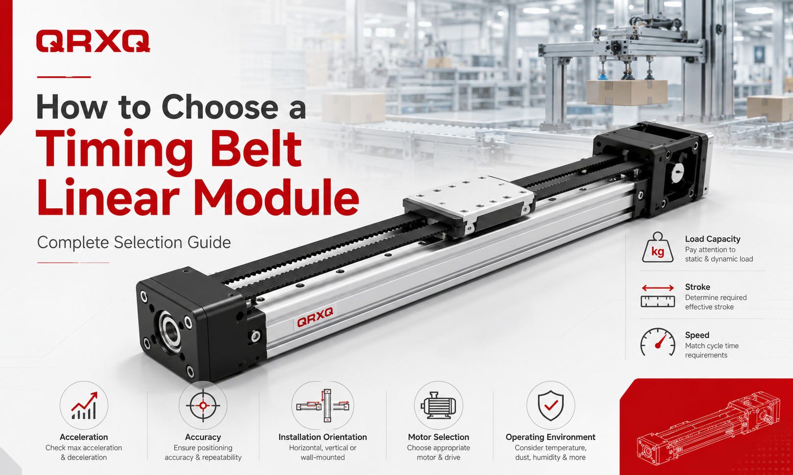
This completetiming belt linear module selection guideexplains the main technical factors involved in choosing and sizing a belt driven linear actuator. It also provides a practical selection process and checklist for packaging machinery, pick and place systems, material handling equipment, electronics assembly lines, vision inspection systems, logistics automation andmulti-axis motion platforms.
Understand the Application Before Selecting a Module
The first step in timingbelt linear moduleselection is to define the actual application requirements. A module should not be selected based only on the maximum payload listed in a product catalog. The operating conditions of the complete machine must be considered.
Before comparing module models, collect the following information:
- Workpiece, fixture and carriage payload
- Required effective stroke
- Maximum travel speed
- Required acceleration and deceleration
- Target cycle time
- Positioning accuracy and repeatability requirements
- Horizontal, vertical, inclined or wall-mounted installation
- Load center position and overhanging distance
- External forces acting on the carriage
- Operating hours and duty cycle
- Available installation space
- Motor and controller type
- Temperature, dust, moisture and cleanroom requirements
These parameters form the basis of the entire selection process. If any critical data is missing, the selected module may not perform reliably under real operating conditions.
Determine the Total Moving Load
Load capacity is one of the most important parameters when selecting a timing belt linear module. The total moving load includes everything carried by the moving carriage, not only the product being transported.
The total moving mass may include:
- Workpiece or product
- Gripper, vacuum cup or end effector
- Mounting plate
- Tooling and fixtures
- Cables, cable chains and pneumatic tubes
- Additional linear axes mounted on the carriage
- Sensors, cameras, dispensers or processing heads
For example, if the workpiece weighs 12 kg, the fixture weighs 5 kg, the gripper weighs 3 kg and the cable chain contributes an equivalent moving load of 2 kg, the total moving load is 22 kg rather than 12 kg.
A safety factor should be applied to account for acceleration forces, operating variations, impact loads and future design changes. For stable horizontal applications, a moderate safety margin may be sufficient. For high acceleration, vertical installation, frequent start-stop cycles or impact-prone applications, a larger safety factor should be used.
The catalog payload should never be treated as the only selection limit. Engineers must also verify allowable load moments and dynamic operating conditions.
Check the Allowable Load Moments
A timing belt module carriage is often subjected to more than a direct downward load. When the load center is positioned away from the center of the carriage, the module experiences a moment load.
The three common moment directions are:
- Pitching moment:the load tilts the carriage forward or backward
- Yawing moment:the load rotates the carriage horizontally
- Rolling moment:the load twists the carriage around the direction of travel
The load moment is related to both load force and overhanging distance. A relatively light payload can still create a large moment if it is mounted far away from the carriage center.
As a basic principle:
Load moment = Load force × Distance from the carriage center
When selecting a module, compare the calculated moment with the manufacturer's allowable static and dynamic moment ratings. A sufficient safety margin should be maintained, especially in high-speed applications.
If the moment load is too high, possible solutions include:
- Selecting a larger module with a wider guide rail
- Using a longer carriage or double carriage configuration
- Reducing the overhanging distance
- Moving the load center closer to the guide system
- Using two parallel modules
- Adding an external support guide
Select the Required Stroke Length
The specified stroke should include more than the distance between the two working positions. Additional travel is usually required for acceleration, deceleration, mechanical clearance, sensor adjustment and installation tolerances.
The required module stroke may include:
- Effective process travel
- Workpiece loading and unloading clearance
- Acceleration and deceleration distance
- End-position safety allowance
- Home sensor and limit sensor space
- Tool or fixture dimensions
- Future process adjustment allowance
For example, if the process requires 1,500 mm of effective travel, selecting a module with exactly 1,500 mm of stroke may not provide enough usable movement. The actual required stroke may be 1,600 mm or more after safety clearances are included.
Timing beltlinear modulesare especially suitable for long-stroke applications because they are not limited by the critical rotational speed of a long ball screw. However, very long modules require careful evaluation of belt tension, aluminum profile rigidity, guide rail support, installation straightness and vibration.
Calculate the Required Speed
The maximum speed should be calculated according to travel distance and cycle time rather than estimated subjectively. The module must complete acceleration, constant-speed travel and deceleration within the available movement time.
For short strokes, the module may never reach its catalog maximum speed because most of the travel is used for acceleration and deceleration. In these cases, acceleration capability has a greater influence on cycle time than maximum speed.
When determining the required speed, consider:
- Effective travel distance
- Required movement time
- Acceleration and deceleration time
- Load mass
- Settling time after stopping
- Control system response
- Maximum allowable vibration
The selected module should have a maximum rated speed above the actual operating speed. Continuous operation at the absolute mechanical limit may reduce service life and increase noise, vibration and belt wear.
Evaluate Acceleration and Deceleration
Acceleration is a critical factor in high-speed pick and place, sorting, packaging and electronics assembly applications. Higher acceleration can shorten cycle time, but it also increases inertial force.
The basic relationship is:
Inertial force = Moving mass × Acceleration
As acceleration increases, the timing belt, pulley, carriage, guide blocks, bearings, motor and mounting structure must withstand greater dynamic forces.
Excessive acceleration may cause:
- Belt tooth deformation or belt jumping
- Carriage vibration
- Motor overload alarms
- Reduced positioning repeatability
- Loose fasteners
- Premature guide block wear
- Longer settling time
Acceleration and deceleration should be selected according to the actual payload and mechanical rigidity of the system. Smooth S-curve motion profiles are often preferred over sudden acceleration changes because they reduce mechanical shock and vibration.
Define the Required Accuracy
Timing belt modules are normally selected for high-speed and long-stroke motion rather than ultra-precision positioning. Therefore, it is important to distinguish between positioning accuracy, repeatability and motor resolution.
Positioning Accuracy
Positioning accuracy describes how closely the carriage reaches the commanded absolute position across the full stroke. It may be influenced by belt elasticity, belt pitch error, pulley accuracy, profile straightness, guide accuracy, load variation and control system calibration.
Repeatability
Repeatability describes the ability of the carriage to return to the same position repeatedly under the same operating conditions. Many automation processes depend more on repeatability than absolute positioning accuracy.
Motor Resolution
Motor or encoder resolution indicates the smallest theoretical command increment. It does not guarantee that the mechanical system can achieve the same level of actual positioning accuracy.
For applications such as packaging, material transfer, sorting and general pick and place, timing belt modules often provide sufficient performance. For semiconductor processing, precision measurement, micro-assembly or machining operations requiring extremely high absolute accuracy, a ball screw or linear motor module may be more suitable.
When evaluating accuracy, engineers should confirm:
- Required absolute positioning accuracy
- Required repeatability
- Allowable settling time
- Load variation during operation
- Whether external position feedback is required
- Whether error compensation is possible
Consider the Installation Orientation
The installation direction directly affects the load, motor torque, braking requirements and safety design of a timing belt linear module.
Horizontal Installation
Horizontal installation is the most common configuration. The motor mainly needs to overcome inertia, friction, cable resistance and external process forces. Payload capacity is generally higher than in vertical applications.
Vertical Installation
In a vertical installation, the motor must continuously resist gravity. The required drive torque is higher, and the system must prevent the load from falling during power loss or emergency stops.
Vertical applications normally require:
- A servo motor with an electromagnetic brake
- A sufficient motor torque safety margin
- Controlled acceleration and deceleration
- Mechanical protection against falling loads
- Careful verification of belt tensile capacity
- Emergency stop and power-loss safety measures
Timing belt modules can be used vertically, but they should be selected conservatively. Heavy vertical lifting applications may be better suited to a ball screw actuator,electric cylinderor counterbalanced lifting system.
Wall-Mounted or Side Installation
Side-mounted modules may experience different rolling and pitching moments compared with horizontal modules. The allowable load should be checked according to the actual mounting direction rather than using only the standard horizontal payload value.
Inclined Installation
An inclined module has both horizontal and vertical force components. The motor torque and braking requirement should be calculated according to the installation angle.
Select the Correct Motor
Motor selection must be performed together with the mechanical module selection. A module may have sufficient load capacity but still fail to achieve the required motion if the motor is undersized.
The motor must provide enough torque for:
- Acceleration of the moving mass
- Overcoming friction
- Moving the load against gravity
- External process forces
- Pulley and belt transmission losses
- Cable chain resistance
- Maintaining the required speed
Servo Motor
Servo motors are commonly used when the application requires high speed, high acceleration, closed-loop control, accurate positioning and frequent changes in motion profile. A servo system is generally preferred for industrial timing belt modules.
Stepper Motor
Stepper motors may be suitable for lower-speed applications with moderate loads and simple positioning requirements. However, open-loop stepper systems can lose position if the available torque is exceeded.
Motor Power and Torque Margin
The motor should not operate continuously at its maximum torque. Adequate torque margin is necessary for load variation, friction changes, acceleration peaks and long-term operation.
Motor selection should verify:
- Continuous torque
- Peak torque
- Maximum rotational speed
- Rotor inertia
- Load inertia ratio
- Brake requirement
- Encoder resolution
- Driver voltage and current
Check Pulley Ratio and Belt Speed
The pulley diameter and transmission ratio affect carriage speed, motor speed, output force and positioning resolution. A larger drive pulley produces more linear travel per motor revolution, increasing speed but reducing the available linear driving force for the same motor torque.
A smaller pulley increases linear force and resolution but may require a higher motor speed to reach the same carriage velocity.
The selected pulley configuration should ensure that:
- The motor does not exceed its rated speed
- The timing belt does not exceed its allowable speed
- The available linear force is sufficient
- The pulley has enough teeth engaged with the belt
- The belt bending radius is acceptable
- The required positioning resolution can be achieved
Evaluate Duty Cycle and Operating Frequency
A module that moves occasionally has different requirements from one operating continuously for multiple shifts. Duty cycle affects motor temperature, bearing life, belt fatigue, lubrication intervals and overall service life.
Important operating factors include:
- Cycles per minute
- Operating hours per day
- Number of working days per year
- Acceleration frequency
- Average and peak load
- Continuous or intermittent motion
- Time spent at maximum speed
For high-frequency production equipment, the module should be selected with additional mechanical and motor capacity. Maintenance accessibility should also be considered during machine design.
Consider the Operating Environment
Environmental conditions can significantly affect the reliability of a timing belt module. Standard open modules may not be suitable for dusty, wet, corrosive, cleanroom or high-temperature environments.
Dust and Particles
Dust can enter the guide rail, belt and pulley areas, increasing wear and affecting motion quality. A covered or fully enclosed module may be required for woodworking, packaging powder, machining debris or similar environments.
Moisture and Corrosion
Humid or washdown environments may require corrosion-resistant fasteners, protective covers, sealed bearings and special surface treatments. Standard aluminum and steel components should not be assumed to be suitable for direct water exposure.
Cleanroom Applications
Cleanroom applications require low-particle materials, controlled lubrication, reduced wear debris and suitable cable management. A standard timing belt module may need special cleanroom preparation.
Temperature
Temperature affects belt material, lubricant viscosity, motor performance and aluminum profile expansion. High-temperature or low-temperature applications require compatible belts, grease, seals and sensors.
Corrosive Chemicals
Applications involving chemicals, acids, solvents or salt spray may require stainless steel components, protective coatings or complete isolation from the process environment.
Verify Module Rigidity and Mounting Surface
The performance of a timing belt linear module depends not only on the module itself but also on the machine frame and mounting surface. A rigid module installed on an uneven or flexible structure may still experience vibration and positioning errors.
The mounting surface should be:
- Flat and straight
- Rigid enough to support dynamic loads
- Free from twisting and local deformation
- Properly aligned with connected axes
- Equipped with suitable fastening points
Long-stroke modules may require support along the full length of the aluminum profile. Unsupported spans can cause profile deflection, guide misalignment and vibration.
When two modules are used in parallel, careful alignment is essential. Poor parallelism can create internal stress, uneven guide wear and increased motor load.
Plan Cable and Pneumatic Line Management
Cables and pneumatic tubes create additional resistance and can influence the actual moving load. A cable chain should be selected according to travel length, bending radius, filling ratio and operating speed.
Incorrect cable management may cause:
- Unstable resistance during motion
- Cable fatigue and breakage
- Pneumatic tube kinking
- Additional carriage vibration
- Interference with sensors or machine guards
The cable chain should be included in the load and motor calculations, especially for long-stroke and high-speed systems.
Choose the Appropriate Module Size
Manufacturers usually offer timing belt modules in several profile widths and guide sizes. A larger module generally provides higher load capacity, higher moment resistance and greater rigidity, but it also increases cost, weight and installation space.
Module size should be selected based on:
- Total moving load
- Load moment
- Required stroke
- Speed and acceleration
- Installation direction
- Required rigidity
- Motor size
- Available machine space
Do not automatically select the smallest module that meets the nominal payload. A slightly larger model may provide better rigidity, longer service life and more stable performance in demanding applications.
Single Carriage, Double Carriage or Parallel Modules
A standard single-carriage module is suitable when the load is compact and centered. Other configurations may be required for larger fixtures or high moment loads.
Double Carriage Configuration
Two carriages on one module increase the support length and improve resistance to pitching, yawing and rolling moments. The distance between the carriages should be selected according to fixture dimensions and load distribution.
Parallel Module Configuration
Two synchronized modules can support wide platforms, gantry beams or heavy fixtures. Parallel modules require accurate mechanical alignment and synchronized motor control.
Multi-Axis Configuration
Timing belt modules can be combined into XY, XZ, XYZ and gantry systems. When one module carries another axis, the complete weight of the upper axis, motor, cables, tooling and payload must be included in the lower-axis load calculation.
Compare Timing Belt Modules with Other Drive Types
A timing belt module is not the best choice for every application. The drive system should be selected according to the main performance priority.
| Drive Type | Main Advantages | Typical Limitations | Suitable Applications |
|---|---|---|---|
| Timing belt | High speed, long stroke, low moving mass and cost efficiency | Lower absolute accuracy and rigidity than precision screw systems | Packaging, transfer, sorting, pick and place and logistics |
| Ball screw | High accuracy, high rigidity and strong thrust | Speed and stroke may be limited by screw length and critical speed | Precision assembly, machining, testing and positioning |
| Rack and pinion | Very long stroke, high load and strong transmission capability | Backlash control and lubrication require careful design | Large gantries, heavy handling and long production lines |
| Linear motor | Very high speed, acceleration and direct-drive precision | Higher cost, heat generation and more demanding control requirements | Semiconductor, electronics, high-speed inspection and precision automation |
Common Timing Belt Module Selection Mistakes
Selecting Only by Payload
A module may support the stated mass but fail because of excessive moment load, acceleration force or overhanging distance.
Ignoring the Weight of Fixtures and Cables
The workpiece is only part of the moving mass. Tooling, mounting plates, cable chains and upper axes must also be included.
Using Catalog Maximum Speed as the Operating Speed
Continuous operation near the mechanical limit can increase vibration, heat, noise and wear.
Ignoring Vertical Safety Requirements
Vertical axes require braking, fall protection and sufficient holding torque.
Confusing Repeatability with Absolute Accuracy
A module may return to the same position consistently while still having an absolute position error across the full stroke.
Ignoring Load Moments
A light but highly overhung load may exceed the guide system's moment capacity.
Undersizing the Motor
A mechanically suitable module cannot reach the required acceleration if the motor lacks peak torque.
Ignoring the Mounting Structure
An uneven or flexible machine frame can reduce the performance of even a correctly selected module.
Step-by-Step Timing Belt Module Selection Process
- Define the motion task:Identify the movement direction, effective travel and machine cycle.
- Calculate the total moving load:Include the workpiece, tooling, fixture, cables and additional axes.
- Determine load moments:Calculate pitching, yawing and rolling moments caused by offset loads.
- Confirm the required stroke:Add safety clearances, sensor space and acceleration distance.
- Set speed and acceleration targets:Calculate them from the required cycle time.
- Define accuracy requirements:Separate positioning accuracy, repeatability and resolution.
- Confirm the installation orientation:Horizontal, vertical, inclined or side-mounted.
- Evaluate environmental conditions:Dust, humidity, cleanroom level, temperature and corrosion.
- Select the module size:Verify payload, moment capacity, rigidity and stroke availability.
- Select the motor and pulley ratio:Check continuous torque, peak torque, speed and inertia.
- Verify service life and duty cycle:Consider operating hours and movement frequency.
- Review installation requirements:Confirm mounting flatness, alignment and cable management.
- Apply a safety margin:Avoid operating continuously at catalog limits.
- Confirm the final configuration:Review the module, motor, controller, sensors, brake and accessories as one complete system.
Timing Belt Linear Module Selection Checklist
- What is the total moving mass?
- Where is the load center located?
- What are the pitching, yawing and rolling moments?
- What effective stroke is required?
- What additional safety travel is needed?
- What is the required maximum speed?
- What acceleration and deceleration are required?
- What is the target cycle time?
- What positioning accuracy is required?
- What repeatability is required?
- Is the module installed horizontally or vertically?
- Does the vertical axis require a motor brake?
- What external process forces act on the carriage?
- How many cycles will the module complete per day?
- Is the environment dusty, wet, corrosive or cleanroom-controlled?
- Is the mounting surface sufficiently flat and rigid?
- Are cable chains and pneumatic tubes included in the calculation?
- Does the motor provide sufficient continuous and peak torque?
- Does the motor speed match the pulley ratio?
- Is a single carriage, double carriage or parallel-axis configuration required?
- Is adequate capacity reserved for future changes?
Example of Timing Belt Module Selection
Consider a material handling application with the following requirements:
- Workpiece weight: 18 kg
- Fixture and gripper weight: 7 kg
- Cable chain equivalent moving load: 3 kg
- Effective stroke: 2,000 mm
- Maximum speed: 1,500 mm/s
- Acceleration: 4 m/s²
- Horizontal installation
- Moderate positioning accuracy requirement
- Continuous two-shift operation
The total moving load is at least 28 kg before applying a safety factor. The engineer must then calculate the inertial force generated during acceleration, verify the load center and moment values, add end clearances to the effective stroke and select a module with sufficient dynamic capacity.
The motor must be able to accelerate the complete moving mass while overcoming friction and cable chain resistance. Because the application operates for two shifts, the module should not be selected at its absolute load and speed limits. A larger profile or guide size may provide better reliability and longer service life.
Frequently Asked Questions
What is the most important factor when selecting a timing belt linear module?
No single parameter is sufficient. Total moving load, load moment, stroke, speed, acceleration, accuracy and installation orientation must be evaluated together.
Can a timing belt module be used for vertical lifting?
Yes, but the motor must overcome gravity and should normally include a brake. Belt capacity, holding torque and fall-protection measures must also be verified.
How much safety margin should be reserved?
The required margin depends on acceleration, duty cycle, impact, installation direction and environmental conditions. High-frequency or vertical applications generally require a larger margin than stable horizontal applications.
Is the maximum catalog payload valid at maximum speed?
Not necessarily. Catalog limits may be specified under particular test conditions. Payload, speed, acceleration and load moments should be evaluated as a combined operating condition.
Are timing belt modules suitable for precision positioning?
They provide good repeatability for many industrial automation tasks, but they are generally less suitable than ball screw or linear motor modules for ultra-high absolute positioning accuracy.
How do I select the motor size?
Calculate the torque required for acceleration, friction, gravity and external forces. Then verify continuous torque, peak torque, maximum speed, load inertia ratio and brake requirements.
When should two carriages be used?
Two carriages are useful when the fixture is long, the load is highly offset or the application generates significant pitching, yawing or rolling moments.
Conclusion
Selecting the correct timing belt linear module requires a systematic evaluation of the complete motion system. Payload and stroke are only the starting points. Speed, acceleration, load moments, installation direction, accuracy, motor torque, duty cycle, environmental conditions and mounting rigidity all affect the final performance and service life of the module.
A properly selected timing belt module provides fast, stable and cost-effective linear motion for packaging machinery, material handling, pick and place, electronics assembly, vision inspection, logistics automation and multi-axis systems. By calculating the real operating conditions, applying appropriate safety margins and verifying the module and motor as one integrated system, engineers can reduce selection risks and achieve reliable long-term operation.
