 English

A timing belt linear module can be used as a single motion axis, but its high speed, long stroke and flexible motor arrangement make it especially suitable for multi-axis automation systems. By combining two or more modules, engineers can create XY positioning platforms, XZ handling systems, XYZ motion systems and large-format gantry mechanisms.
Designing a multi-axis system involves more than mounting one linear module on top of another. The designer must consider axis orientation, moving mass, load distribution, structural rigidity, motor placement, cable routing and synchronization. Each added axis changes the load applied to the supporting axis, so the complete system must be evaluated as an integrated mechanical structure.
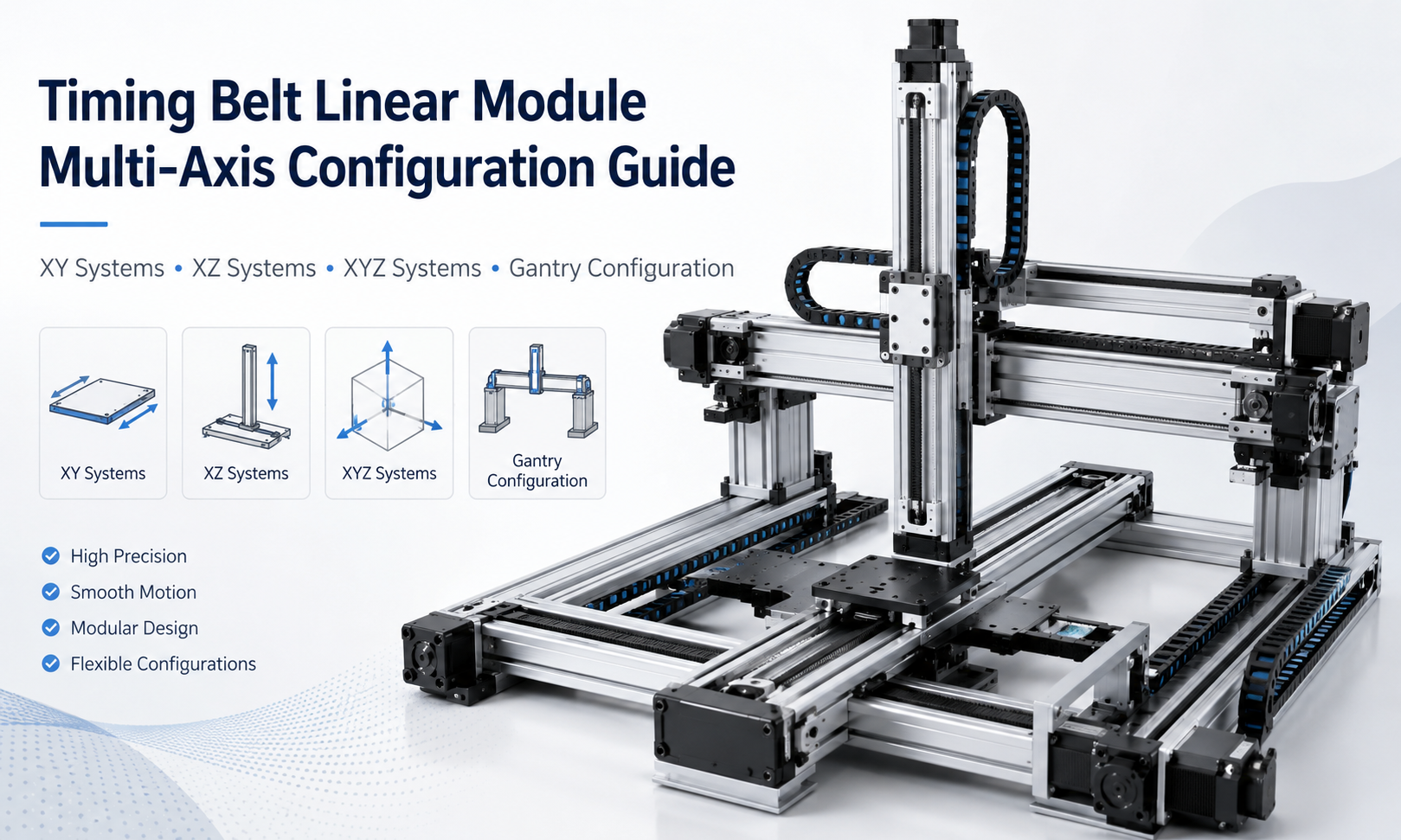
Table of Contents
- What Is a Multi-Axis Timing Belt Linear Module System?
- Common Multi-Axis Configurations
- XY Timing BeltLinear Module Systems
- XZ Timing Belt Linear Module Systems
- XYZ Timing Belt Linear Module Systems
- Timing Belt Gantry Systems
- Axis Combination and Structural Arrangement
- Load Distribution in Multi-Axis Systems
- Motor Arrangement and Transmission Layout
- Cable Management for Multi-Axis Motion
- Synchronization and Motion Control
- Multi-Axis Configuration Design Process
- Common Design Mistakes
- Frequently Asked Questions
- Conclusion
What Is a Multi-Axis Timing Belt Linear Module System?
A multi-axis timing belt linear module system combines two or more linear motion axes to move a payload in multiple directions. Each module normally provides motion along one straight axis, while the complete mechanism creates two-dimensional or three-dimensional positioning capability.
For example, an X-axis module can provide horizontal travel, while a second module mounted on its carriage provides Y-axis motion. Adding a vertical Z-axis creates a three-axis system capable of positioning a tool, sensor, gripper or workpiece at different coordinates.
Timing belt modules are commonly selected for multi-axis systems because they provide:
- High linear speed
- Long available travel
- Relatively low moving mass
- Flexible motor mounting directions
- Simple integration with servo or stepper motors
- Good suitability for repeated transfer and positioning cycles
However, a timing belt system is generally selected for applications that prioritize speed, stroke and cycle time rather than extremely high thrust or ultra-fine positioning accuracy.
Common Multi-Axis Configurations
The most common timing belt linear module combinations are XY, XZ, XYZ and gantry configurations. The correct structure depends on the required motion directions, working envelope, payload orientation and machine layout.
| Configuration | Motion Directions | Typical Structure | Common Applications |
|---|---|---|---|
| XY system | Horizontal and lateral | One axis mounted on the carriage of another axis | Dispensing, inspection, sorting and planar positioning |
| XZ system | Horizontal and vertical | Vertical axis mounted on a horizontal traveling axis | Pick-and-place, loading, unloading and stacking |
| XYZ system | Three-dimensional motion | Three perpendicular axes combined in sequence | Assembly, testing, handling and automated processing |
| Gantry system | Large-area horizontal motion with optional vertical axis | Crossbeam supported by two parallel axes | Large-format handling, palletizing and machine loading |
XY Timing Belt Linear Module Systems
An XY system provides motion in two perpendicular horizontal directions. It is one of the most common multi-axis arrangements for flat working areas.
The lower axis is normally called the X-axis and supports the upper Y-axis. The Y-axis is mounted on the X-axis carriage, so the complete mass of the Y-axis, its motor, tooling and payload becomes a moving load on the X-axis.
Typical XY Structure
A standard XY arrangement includes:
- One long-stroke X-axis module
- One Y-axis module mounted perpendicular to the X-axis
- A connection plate between the two axes
- Separate motors for X-axis and Y-axis motion
- A cable carrier for the moving upper axis
- A controller for coordinated two-axis positioning
XY System Design Considerations
The lower X-axis must be selected according to the total moving mass rather than only the external payload. This total includes the Y-axis body, carriage, motor, connection plate, cable carrier, tooling and workpiece.
The length of the Y-axis also creates a moment load on the X-axis carriage. A wide mounting plate, dual guide structure or two parallel X-axis modules may be required when the Y-axis is long or when the payload is positioned far from the supporting carriage.
XY timing belt platforms are commonly used for dispensing, visual inspection, marking, sorting, scanning and automatic positioning over a rectangular working area.
XZ Timing Belt Linear Module Systems
An XZ system combines horizontal movement with vertical movement. It is widely used in pick-and-place equipment, material loading systems, stacking units and transfer mechanisms.
The X-axis normally moves the complete Z-axis horizontally. The Z-axis raises or lowers the gripper, suction cup, tool or payload.
Vertical Axis Load Requirements
The Z-axis must overcome gravity in addition to acceleration and process forces. The required motor torque should therefore be calculated from the moving mass, pulley radius, acceleration, transmission efficiency and safety factor.
A vertical timing belt axis may also require:
- A brake motor to prevent falling during power loss
- A counterbalance mechanism for heavier moving loads
- A mechanical stop or falling-prevention device
- A suitable homing and limit sensor arrangement
- A controlled deceleration strategy near the lower travel limit
Vertical Axis Mounting Direction
The Z-axis may be mounted with the module body moving or with the carriage moving. A moving-body arrangement can reduce the cantilever distance between the tool and the guide structure, while a moving-carriage arrangement may simplify installation.
The correct method depends on the required stroke, tooling shape, available space and moment load. The vertical axis should remain as compact and lightweight as practical because its complete mass is carried by the horizontal axis.
XYZ Timing Belt Linear Module Systems
An XYZ system provides motion along three perpendicular directions and can position a tool or workpiece throughout a three-dimensional working volume.
A typical structure uses a long X-axis as the base, a Y-axis mounted on the X-axis carriage and a Z-axis mounted on the Y-axis carriage. Other arrangements are also possible depending on the machine frame and working direction.
Axis Hierarchy
Axis hierarchy is important because each lower-level axis carries all axes installed above it. In a conventional stacked XYZ arrangement:
- The Z-axis carries the tool and payload.
- The Y-axis carries the Z-axis, tool and payload.
- The X-axis carries the Y-axis, Z-axis, motors, tooling, cables and payload.
As a result, the base axis usually requires the highest load capacity and structural rigidity. It may also require a larger motor or a stronger module series than the upper axes.
Reducing Moving Mass
Reducing moving mass improves acceleration, cycle time and positioning stability. Common methods include:
- Using compact modules for upper axes
- Mounting motors in positions that reduce cantilever loads
- Using lightweight aluminum connection plates
- Reducing unnecessary tooling mass
- Selecting the shortest practical upper-axis stroke
- Separating stationary electrical components from the moving assembly
The fastest module is not always the best choice. The complete system should be optimized for total moving mass, rigidity and required cycle time.
Timing Belt Gantry Systems
A gantry system uses a crossbeam supported by two sides of the machine frame. It is suitable for large working areas, long strokes and applications where the moving bridge must remain stable across a wide span.
The gantry may use one powered axis and one passive support axis, or two independently driven parallel axes. The correct arrangement depends on the span, payload, acceleration and required positioning performance.
Single-Drive Gantry Configuration
In a single-drive gantry, one motor drives both sides through a mechanical connection such as a common shaft, timing belt or transmission system. This provides mechanical synchronization and can simplify control.
The mechanical connection must be sufficiently rigid to prevent torsional deformation and angular misalignment across the crossbeam.
Dual-Drive Gantry Configuration
In a dual-drive gantry, each side has its own motor and drive system. The controller commands both axes to move together while monitoring their positions.
Dual-drive systems are suitable for wide gantries, long strokes and higher dynamic loads, but they require careful homing, alignment and synchronization. A position difference between the two sides can twist the crossbeam, overload the guides or cause the mechanism to jam.
Gantry Crossbeam Design
The crossbeam must resist bending and torsion during acceleration. Its stiffness depends on the beam profile, unsupported span, tooling position and payload.
A lightweight beam improves acceleration, but insufficient stiffness can create vibration and positioning error. The beam should therefore be designed according to both static deflection and dynamic response.
Axis Combination and Structural Arrangement
Multi-axis modules should not be combined only according to available mounting holes. The connection between axes must provide sufficient rigidity, alignment and support.
Connection Plate Design
Connection plates are used to mount one axis to another. A suitable plate should:
- Provide a flat mounting surface
- Distribute the load across the carriage
- Minimize unnecessary overhang
- Resist bending under acceleration
- Allow motor, sensor and cable installation
- Provide access for assembly and maintenance
Very thick plates increase moving mass, while thin plates may deform. Plate thickness and reinforcement should be selected according to the load and cantilever distance.
Module Orientation
A module may be installed horizontally, vertically, on its side or in an inverted orientation. However, the allowable payload and moment capacity can change with the mounting direction.
The designer should verify radial load, axial load and moment load for the actual installation orientation rather than relying only on a general payload value.
Load Distribution in Multi-Axis Systems
Load calculation is one of the most important parts of multi-axis design. The lower axis does not carry only the workpiece. It carries the complete moving assembly installed above it.
Total Moving Load
The total moving load may include:
- Upper linear modules
- Servo or stepper motors
- Gearboxes and couplings
- Connection plates and brackets
- Cable carriers and cables
- Sensors and pneumatic components
- End tooling
- The transported workpiece
This total mass should be used when calculating acceleration force, required motor torque and dynamic loading.
Moment Load
Moment load occurs when the payload center of gravity is offset from the carriage or guide center. Long upper axes and cantilevered tooling can create significant pitching, yawing or rolling moments.
Moment load can be reduced by:
- Moving the payload closer to the guide center
- Using a wider carriage
- Increasing the distance between guide blocks
- Using two parallel support axes
- Shortening the cantilever length
- Reducing upper-axis mass
Dynamic Load
Acceleration and deceleration create forces that may be much higher than the static load. A system that moves smoothly at low speed may vibrate, deflect or lose positioning stability when operated at high acceleration.
The selected module should therefore be evaluated under the intended speed, acceleration, duty cycle and emergency-stop conditions.
Motor Arrangement and Transmission Layout
Motor placement affects system size, moving mass, cable routing and maintenance access. Timing belt modules often allow motors to be installed directly, in parallel or through a folded return arrangement.
Moving Motor Arrangement
When a motor is mounted on an upper moving axis, its mass is carried by every supporting axis below it. This increases the required load capacity and motor torque of the lower axes.
Moving motor arrangements are mechanically simple, but they require flexible power and encoder cables.
Stationary Motor Arrangement
Some mechanical layouts allow the motor to remain stationary while the axis structure moves. This can reduce moving mass and cable movement, but it may require a more complex belt path, shaft system or transmission arrangement.
Motor Orientation
Motor orientation should be selected according to:
- Available installation space
- Risk of collision with adjacent axes
- Maintenance access
- Cable bend radius
- Protection from dust, coolant or process debris
- System center of gravity
The motor should not be positioned where it unnecessarily increases the cantilever distance or interferes with the working area.
Cable Management for Multi-Axis Motion
Cable routing becomes more complex as the number of axes increases. Each moving axis may require motor power cables, encoder cables, sensor wires, pneumatic tubes, vacuum lines or communication cables.
Cable Carrier Selection
A cable carrier should have sufficient internal space and a bend radius that meets the requirements of all installed cables and tubes. Overfilling the carrier can increase friction and shorten cable life.
Different cable types should be separated where necessary to reduce electrical interference and abrasion.
Nested Cable Movement
In an XYZ system, the Z-axis cables may move with the Y-axis, while the Y-axis cables move with the X-axis. This creates multiple levels of cable movement.
The cable routing should be planned during the mechanical design stage rather than added after assembly. Suitable fixed points, moving points, bend directions and service loops should be defined for every axis.
Avoiding Cable-Related Problems
- Do not allow cables to rub against sharp edges.
- Do not exceed the minimum bend radius.
- Do not place connectors inside continuously bending sections.
- Do not mix flexible and non-flexible cables in the same moving path without evaluation.
- Provide strain relief at both fixed and moving connection points.
- Check that the cable carrier does not enter the working area.
Synchronization and Motion Control
Multi-axis systems require a controller capable of coordinating several motors. The required control level depends on whether the axes move independently, sequentially or simultaneously along a defined path.
Independent Axis Motion
In simple transfer equipment, one axis may complete its movement before the next axis starts. This reduces control complexity and may be sufficient for basic loading and unloading cycles.
Interpolated Motion
Dispensing, cutting, scanning and contour-following applications may require two or three axes to move simultaneously. The controller must perform linear or circular interpolation while maintaining the required speed and path accuracy.
Dual-Axis Gantry Synchronization
A dual-drive gantry requires both parallel axes to maintain the same position. The controller may use master-slave control, electronic gearing or a gantry synchronization function.
Both sides should have appropriate homing sensors or reference procedures. The control system should also monitor following error so that the machine can stop before excessive misalignment damages the structure.
Multi-Axis Configuration Design Process
A systematic design process helps prevent oversizing, insufficient rigidity and integration problems.
- Define the working envelope.Determine the required X, Y and Z travel, including safety margins and tool dimensions.
- Define the payload.Calculate the mass and center of gravity of the workpiece, tooling, brackets and upper axes.
- Select the axis hierarchy.Decide which axis supports the others and identify the total moving mass on each axis.
- Calculate dynamic requirements.Determine speed, acceleration, deceleration, travel time and cycle time.
- Check load and moment capacity.Evaluate radial loads, axial loads and pitching, yawing and rolling moments.
- Select the module size.Choose the appropriate profile, guide structure, belt size, carriage length and motor capacity.
- Design connection components.Create rigid mounting plates, brackets and crossbeams with suitable flatness.
- Plan motor positions.Confirm space, collision clearance, cable routing and maintenance access.
- Plan cable management.Select cable carriers, bend radii, routing directions and fixed points.
- Define the control method.Confirm independent motion, interpolation or gantry synchronization requirements.
- Verify the machine frame.Ensure the base and support structure are sufficiently rigid and level.
- Test the complete system.Commission at reduced speed before gradually increasing acceleration and cycle rate.
Common Design Mistakes
Calculating Only the External Payload
Ignoring the mass of upper axes, motors and connection plates can result in an undersized supporting axis. The complete moving assembly must be included in the load calculation.
Ignoring Moment Loads
A payload may be within the rated mass but still exceed the allowable moment because it is positioned far from the carriage center.
Using an Insufficiently Rigid Connection Plate
A flexible plate can reduce positioning stability even when the linear modules themselves are sufficiently rigid.
Installing a Heavy Axis on Top
An unnecessarily large upper axis increases the load and motor requirements of every lower axis. Upper axes should be kept compact whenever possible.
Planning Cable Routing Too Late
Adding cable carriers after mechanical assembly may reduce available stroke, create interference or force cables into an unsuitable bend radius.
Ignoring Gantry Alignment
Parallel gantry axes must be installed accurately. Poor alignment increases guide resistance, belt load and motor current.
Using Excessive Acceleration
High acceleration may create vibration, frame deflection, belt oscillation and loss of positioning stability even when the motor has sufficient power.
Frequently Asked Questions
Can timing belt linear modules be used for XYZ systems?
Yes. Timing belt modules are widely used in XYZ systems that require long travel, high speed and moderate positioning accuracy. The base axis must be sized for the complete mass of all upper axes, tooling and payload.
Which axis should have the largest load capacity?
In a conventional stacked system, the lowest supporting axis usually requires the highest load capacity because it carries all upper axes and moving components.
When should two parallel axes be used?
Two parallel axes may be required when the crossbeam is wide, the payload creates a large moment, or a single carriage cannot provide sufficient support and rigidity.
Does a dual-drive gantry need synchronization control?
Yes. Two independently driven sides must remain synchronized during homing and operation. The controller should monitor the position difference and stop the system if the allowable deviation is exceeded.
Can a timing belt module be used as a vertical Z-axis?
Yes, but the motor must overcome gravity and the system should include suitable power-off protection, such as a brake motor, counterbalance or mechanical falling-prevention device.
How can moving mass be reduced?
Use smaller upper-axis modules, lightweight connection plates, compact tooling, appropriate motor positions and the shortest practical upper-axis strokes.
Are timing belt multi-axis systems suitable for precision machining?
They are suitable for many automated positioning, transfer, dispensing, inspection and handling tasks. Applications requiring very high rigidity, heavy cutting forces or ultra-fine positioning may require a ball screw or linear motor system instead.
Conclusion
Timingbelt linear modulescan be combined into flexible XY, XZ, XYZ and gantry motion systems for high-speed automation. Successful integration depends on selecting the correct axis hierarchy, calculating the complete moving load, controlling moment loads and providing sufficient structural rigidity.
Motor placement, cable routing and synchronization should be considered from the beginning of the design process. By evaluating the complete mechanism rather than treating each axis separately, engineers can build a multi-axis system with stable motion, efficient cycle times and reliable long-term operation.
