 English

Atiming belt linear moduleis a high-speed linear motion unit commonly used in material handling, pick-and-place systems, packaging machinery, visual inspection equipment, electronic assembly lines and multi-axis automation systems. Correct installation is essential for maintaining positioning accuracy, smooth movement, low operating noise and long service life.
Even when the module itself has been assembled and tested at the factory, an unsuitable mounting surface, incorrect alignment, excessive tightening force, improper motor installation or poorly arranged cables can reduce its performance. These installation problems may cause vibration, abnormal noise, belt deviation, guide rail wear, positioning errors and premature component failure.
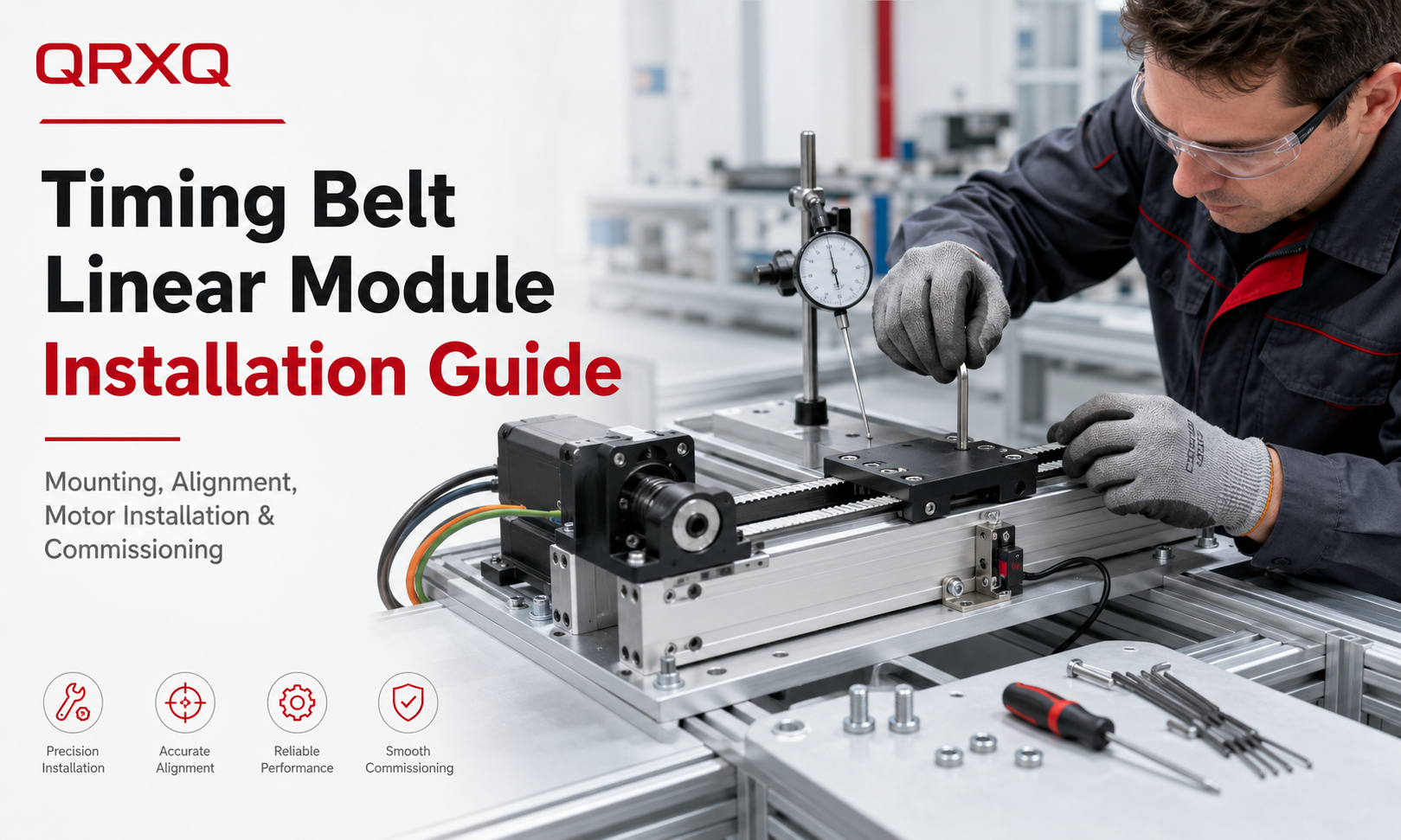
Thistiming belt linear module installation guideexplains the complete installation process, including mounting surface preparation, horizontal and vertical mounting, module alignment, motor installation, sensor adjustment, cable routing, commissioning and final inspection.
Why Correct Installation Is Important
A timingbelt linear modulecombines several mechanical components, including an aluminum base, linear guide, guide blocks, carriage, timing belt, drive pulley, idler pulley, motor mount and sensors. These components must remain correctly aligned after the module is installed on the machine frame.
If the mounting surface is uneven or the module is forced into position during installation, the base may become twisted or deformed. This deformation changes the alignment of the guide rail and increases resistance during movement.
Common problems caused by incorrect installation include:
- Increased running resistance
- Abnormal vibration or noise
- Uneven carriage movement
- Reduced positioning accuracy
- Timing belt deviation or premature wear
- Guide block and guide rail damage
- Motor overload or servo alarm
- Reduced service life of the complete module
For this reason, installation should be treated as part of the precision assembly process rather than simply fastening the module to a machine frame.
Preparation Before Installation
Before installing the timing belt linear module, confirm that the selected model meets the application requirements for load, stroke, speed, acceleration, installation orientation and environmental conditions.
Prepare the required tools and measuring equipment before beginning the installation.
- Torque wrench
- Hex keys and suitable screwdrivers
- Dial indicator
- Precision straightedge
- Error gauge
- Spirit level or electronic level
- Cleaning cloth and industrial cleaner
- Thread-locking compound where required
- Alignment pins or positioning blocks
- Personal protective equipment
Before unpacking or handling the module, review the product drawing, mounting dimensions, bolt specifications, motor interface and sensor wiring diagram.
Inspect the Timing Belt Linear Module
Inspect the module before installation to make sure it has not been damaged during transportation or storage.
Check the following items:
- The aluminum base is not bent, dented or cracked.
- The carriage moves smoothly through the available stroke.
- The timing belt is not damaged, loose or twisted.
- The motor mount and end covers are secure.
- The cable connectors and sensor cables are intact.
- The mounting holes and reference surfaces are clean.
- No foreign objects are present inside the module.
Do not force the carriage to move if it feels blocked. First inspect the mechanical structure, shipping locks and protective components.
Mounting Surface Preparation
The quality of the mounting surface directly affects the straightness, parallelism and running resistance of the module. The machine frame should have sufficient rigidity to resist deformation under the module weight, payload and acceleration forces.
Clean the Mounting Surface
Remove oil, dust, paint residue, metal chips, burrs and other contaminants from the mounting surface. Small particles trapped between the module base and machine frame can create local deformation after the mounting bolts are tightened.
Clean both the machine mounting surface and the bottom reference surface of the module with a lint-free cloth.
Check Surface Flatness
Use a precision straightedge, feeler gauge or dial indicator to inspect the mounting surface. The acceptable flatness depends on the module length, size and accuracy requirements.
For high-precision applications, the mounting surface should be machined rather than welded or manually ground. If the frame is welded, it may need stress relief and finish machining before installation.
Check Structural Rigidity
The mounting frame must remain stable during rapid acceleration and deceleration. A weak frame can vibrate even when the linear module is correctly installed.
Additional support may be required for:
- Long-stroke modules
- High-speed applications
- Heavy payloads
- Offset loads
- Gantry structures
- Vertical or cantilever installations
Determine the Installation Direction
Timing beltlinear modulescan be installed horizontally, vertically, sideways or upside down, depending on the module design and application requirements. However, the allowable load and load moment may change according to the installation direction.
Before installation, confirm:
- The direction of carriage movement
- The motor installation side
- The cable outlet direction
- The position of the home sensor
- The position of the positive and negative limit sensors
- The available maintenance space
- The direction of the external load
Incorrect orientation may cause cable interference, insufficient maintenance access or excessive moment load on the guide system.
Horizontal Installation
Horizontal installation is the most common mounting method for timing belt linear modules. In this configuration, the payload acts mainly in the vertical direction.
Horizontal Installation Procedure
- Place the module carefully on the prepared mounting surface.
- Align the module reference edge with the positioning shoulder, locating blocks or alignment pins.
- Insert the mounting bolts without fully tightening them.
- Move the carriage slowly through the complete stroke and check for abnormal resistance.
- Measure module straightness and parallelism.
- Tighten the mounting bolts gradually from the center toward both ends.
- Apply the specified tightening torque.
- Move the carriage again to confirm smooth operation.
Do not tighten one end completely before securing the other end. Uneven tightening can twist the aluminum base and increase guide rail resistance.
Vertical Installation
Vertical installation requires additional safety considerations because gravity continuously acts on the carriage and payload. If motor power is removed, the carriage may move downward depending on the drive design and load condition.
Requirements for Vertical Installation
- Use a servo motor with an electromagnetic brake where necessary.
- Confirm that the brake holding torque is sufficient for the payload.
- Consider a counterbalance, gas spring or mechanical support for heavy loads.
- Install a mechanical safety stop where falling movement could create danger.
- Do not rely only on the timing belt to hold a suspended load during maintenance.
- Confirm that the motor torque is sufficient to lift the load during acceleration.
Vertical Installation Procedure
- Secure the module with lifting equipment or temporary supports.
- Position the module against the vertical mounting surface.
- Install the mounting bolts loosely.
- Adjust vertical alignment with a precision level or dial indicator.
- Tighten the bolts gradually and evenly.
- Connect the motor brake before removing temporary supports.
- Perform initial movement at low speed and low acceleration.
During commissioning, verify that the carriage does not drop when the emergency stop is activated or when servo power is disconnected.
Side and Inverted Installation
When the module is mounted on its side or upside down, the direction of the load relative to the guide rail changes. The guide blocks may be exposed to higher radial or moment loads.
Check the allowable load ratings provided for the selected installation orientation. For side-mounted modules, pay particular attention to pitching, yawing and rolling moments generated by offset tooling or workpieces.
For inverted installation, ensure that all covers, fasteners, sensors and cable accessories are securely fixed. Components should not become loose and fall into the working area.
Module Alignment and Positioning
Alignment determines whether the carriage can travel smoothly without excessive internal stress. The module should be aligned according to a reliable mechanical reference rather than visual judgment.
Reference Edge Alignment
Many timing belt linear modules have a machined reference edge along the base. Position this edge against a machined shoulder or locating block on the machine frame.
If no reference shoulder is available, use a dial indicator to measure the side of the module while moving the indicator along the full length.
Straightness Adjustment
Place the dial indicator against the module reference surface and move it from one end to the other. Adjust the module position until the measured deviation meets the installation requirement.
For long modules, measure several points along the mounting length. Local deviation can indicate dirt, burrs or uneven support beneath the module.
Height Adjustment
When the module must align with another machine component, measure the carriage height at multiple positions. Use precision shims where necessary.
Do not use soft, compressible or uneven materials as shims. The support must remain stable under repeated load cycles.
Parallelism Adjustment for Multiple Modules
Parallelism is especially important when two timing belt linear modules support one crossbeam or shared platform. If the two axes are not parallel, the system may bind, vibrate or overload the guide blocks.
Dual-Module Alignment Procedure
- Install and fully align the first module as the reference axis.
- Place the second module approximately parallel to the reference module.
- Connect the crossbeam or shared platform without fully tightening all bolts.
- Measure the distance between the two modules at several positions.
- Move the system slowly through the full stroke.
- Adjust the second module until movement remains smooth throughout the stroke.
- Tighten the second module gradually while repeatedly checking movement.
- Measure final parallelism and diagonal dimensions.
For dual-drive gantry systems, mechanical parallelism must be established before electronic gantry synchronization is configured.
Mounting the Payload or Tooling
The payload should be mounted securely to the carriage using the specified threaded holes and fasteners.
Observe the following requirements:
- Keep the payload center of gravity as close to the carriage as possible.
- Avoid unnecessary overhang.
- Use all recommended mounting holes.
- Do not drill additional holes into the carriage without approval.
- Check that mounting screws do not extend too deeply into the carriage.
- Distribute the load evenly across the carriage surface.
- Calculate pitching, rolling and yawing moments for offset loads.
A payload may be within the rated mass limit but still exceed the allowable moment load if its center of gravity is positioned far away from the carriage.
Motor Installation
The motor must be installed correctly to ensure reliable torque transmission and prevent excessive load on the motor shaft, coupling and drive pulley.
Direct Motor Installation
For direct motor mounting:
- Clean the motor flange and mounting interface.
- Confirm that the motor shaft size matches the coupling or pulley bore.
- Insert the motor shaft without impact or forced assembly.
- Align the motor concentrically with the drive shaft.
- Tighten the coupling or locking mechanism according to specification.
- Tighten the motor mounting bolts in a cross pattern.
Do not strike the motor shaft with a hammer. Impact can damage the motor bearings or encoder.
Motor Installation Through a Coupling
When a coupling is used, maintain the required axial spacing between the motor shaft and module drive shaft. Excessive axial compression or shaft misalignment can shorten coupling and bearing life.
Check:
- Angular misalignment
- Parallel offset
- Axial spacing
- Coupling clamping torque
- Motor flange alignment
Side-Mounted or Folded Motor Installation
Some timing belt modules use a side-mounted motor with an additional pulley and belt transmission. In this arrangement, confirm the secondary belt tension, pulley alignment and protective cover installation.
Timing Belt Inspection After Installation
The timing belt is usually tensioned before delivery, but installation stress or motor assembly may affect belt tracking and operating condition.
Inspect the belt for:
- Correct position on the pulley
- No contact with side covers
- No twisting or tooth damage
- No excessive looseness
- No excessive tension
- Consistent movement throughout the stroke
Do not adjust belt tension without following the manufacturer’s procedure. Excessive tension increases bearing load, motor load and belt wear, while insufficient tension can cause vibration, tooth jumping and positioning errors.
Sensor Installation and Adjustment
Timing belt linear modules commonly use a home sensor and positive and negative limit sensors. These sensors define the machine reference position and prevent the carriage from moving beyond the permitted travel range.
Home Sensor
The home sensor is used during the homing cycle. Position it so that the carriage can detect the signal consistently without reaching the mechanical end of travel.
Limit Sensors
Install the positive and negative limit sensors before the mechanical end positions. Leave sufficient stopping distance based on maximum speed, payload and deceleration.
Sensor Adjustment Procedure
- Move the carriage manually or at low speed toward the sensor.
- Observe the sensor indicator and controller input signal.
- Adjust the sensor position until reliable activation is achieved.
- Confirm that the sensor bracket is securely tightened.
- Repeat the test several times from different approach distances.
- Verify the home and limit logic in themotion controller.
Do not place the limit sensor so close to the mechanical stop that the carriage cannot decelerate safely.
Cable Routing and Cable Management
Incorrect cable routing can create drag, interfere with the carriage, damage connectors or introduce additional load into the module.
Follow these cable-routing principles:
- Use a cable carrier for moving motor, sensor and tool cables.
- Maintain the minimum cable bending radius.
- Separate power cables from encoder and signal cables where possible.
- Provide strain relief near connectors.
- Prevent cables from rubbing against sharp edges.
- Leave sufficient cable length for the complete stroke.
- Do not allow cables to hang into the working area.
- Ensure the cable carrier does not pull the carriage sideways.
After installation, move the carriage through the full stroke and observe the cable carrier. It should bend smoothly without twisting, stretching or contacting surrounding structures.
Electrical Connections
Electrical installation should be completed by qualified personnel according to the motor, servo drive, sensor and controller documentation.
Before applying power:
- Confirm the motor phase connections.
- Connect the encoder cable correctly.
- Connect the motor brake where required.
- Verify sensor voltage and output type.
- Check grounding and shielding.
- Confirm emergency-stop wiring.
- Verify the positive and negative travel directions.
Incorrect motor direction or limit sensor logic can cause the carriage to move toward the wrong mechanical end during homing.
Initial Commissioning
Commissioning should begin with conservative motion settings. Do not immediately operate the module at maximum speed or acceleration.
Manual Inspection Before Power-On
Before applying motor power:
- Check that all mounting bolts are tightened.
- Remove tools and temporary supports.
- Confirm that the carriage path is clear.
- Check cable carrier movement.
- Verify sensor positions.
- Confirm that protective covers are installed.
Low-Speed Jogging
Use low-speed jogging to move the carriage a short distance in both directions. Confirm that the actual direction matches the controller command.
Listen for abnormal noise and observe whether the movement is smooth.
Homing Test
Run the homing sequence at low speed. Verify that:
- The carriage moves in the correct homing direction.
- The home sensor activates correctly.
- The controller establishes the reference position.
- The carriage does not contact the mechanical stop.
Full-Stroke Test
Move the carriage gradually through the complete available stroke. Test the positive and negative limit sensors and confirm that software travel limits are correctly configured.
Increase Speed and Acceleration Gradually
Increase speed, acceleration and deceleration in stages while monitoring:
- Motor current
- Servo alarm history
- Vibration
- Noise
- Positioning stability
- Cable carrier movement
- Belt tracking
If vibration or noise increases significantly, stop the test and inspect the mounting rigidity, alignment, belt tension and motion parameters.
Servo Parameter Setup
Servo parameters should match the module load and mechanical characteristics. Excessively aggressive tuning can create vibration, overshoot or belt oscillation.
Important settings include:
- Motor rotation direction
- Electronic gear ratio
- Position loop gain
- Speed loop gain
- Acceleration and deceleration
- Torque limit
- In-position range
- Following error limit
- Brake release timing
For vertical axes, coordinate the motor brake release and servo torque establishment to prevent the load from dropping.
Accuracy and Repeatability Verification
After installation and commissioning, verify that the module meets the required positioning performance.
Measure several target positions across the complete stroke. Approach each position repeatedly from the same direction and, where required, from opposite directions.
Check:
- Repeatability
- Positioning deviation
- Home position repeatability
- Bidirectional positioning difference
- Travel straightness
- Payload stability
If accuracy does not meet the expected value, inspect the mounting surface, module alignment, belt condition, coupling installation, servo tuning and measurement method.
Common Timing Belt Module Installation Mistakes
Installing on an Uneven Surface
An uneven surface can twist the module base and cause excessive guide resistance.
Fully Tightening One End First
This can pull the module out of alignment. Bolts should be tightened gradually and evenly.
Ignoring Load Moment
A long overhanging tool may exceed the allowable moment even when the payload mass is acceptable.
Incorrect Parallel Alignment
Two modules connected by one crossbeam can bind if their guide directions are not parallel.
Improper Motor Coupling Installation
Incorrect coupling spacing or shaft alignment can cause vibration and premature bearing wear.
Setting Limit Sensors Too Close to the End
The module may not have sufficient distance to stop before contacting the mechanical end stop.
Poor Cable Management
Cables that are too short, twisted or unsupported can restrict movement and damage connectors.
Running at Full Speed Immediately
Installation problems are easier and safer to detect during low-speed commissioning.
Timing Belt Linear Module Installation Checklist
| Inspection Item | Requirement |
|---|---|
| Module condition | No transportation damage, deformation or loose components |
| Mounting surface | Clean, flat, rigid and free of burrs |
| Installation direction | Matches the load and application design |
| Module alignment | Straightness and reference-edge position verified |
| Parallelism | Multiple axes aligned without binding |
| Mounting bolts | Tightened evenly to the specified torque |
| Payload installation | Securely mounted with acceptable load moments |
| Motor installation | Shaft, coupling and flange correctly aligned |
| Timing belt | Correct tracking, tension and operating condition |
| Sensors | Home and limit signals tested |
| Cable routing | Correct bending radius, strain relief and full-stroke clearance |
| Electrical wiring | Motor, encoder, brake, grounding and sensors verified |
| Emergency stop | Function tested before normal operation |
| Low-speed test | Smooth movement in both directions |
| Full-stroke test | No interference or mechanical contact |
| Accuracy test | Repeatability and positioning performance confirmed |
Maintenance After Installation
After the initial operating period, inspect the module again because bolts, cable carriers and connected structures may settle during early operation.
Recommended follow-up checks include:
- Retightening mounting bolts where necessary
- Checking timing belt tracking and tension
- Inspecting guide rail lubrication
- Checking motor and coupling fasteners
- Inspecting sensor brackets
- Checking cable carrier wear
- Monitoring abnormal noise and vibration
The inspection interval should be adjusted according to operating speed, payload, cycle frequency and environmental conditions.
Frequently Asked Questions
Can a timing belt linear module be installed vertically?
Yes. However, vertical installation usually requires a motor brake, sufficient holding torque and suitable safety measures to prevent the carriage and payload from falling when power is removed.
Does the module mounting surface need to be machined?
For applications requiring high accuracy, smooth motion or long service life, a machined and sufficiently rigid mounting surface is recommended. An uneven surface can deform the module base.
How should the mounting bolts be tightened?
Install all bolts loosely first, align the module, and then tighten the bolts gradually from the center toward both ends. Use the specified tightening torque.
How are two timing belt modules installed in parallel?
Install one module as the reference axis, align the second module relative to it, connect the crossbeam loosely and move the system through the full stroke while adjusting parallelism.
Should belt tension be adjusted during installation?
Normally, the belt is adjusted before delivery. Do not change the tension unless inspection shows a problem or the manufacturer’s installation procedure requires adjustment.
Why does the module vibrate after installation?
Possible causes include insufficient frame rigidity, uneven mounting surfaces, incorrect alignment, excessive acceleration, unsuitable servo tuning, excessive belt tension or an offset payload.
Conclusion
Correct timing belt linear module installation requires more than tightening several mounting bolts. The mounting surface must be flat and rigid, the module must be accurately aligned, the payload and motor must be installed correctly, and all sensors and cables must be arranged for safe full-stroke movement.
Horizontal, vertical, side and inverted installations each create different load and safety requirements. For multi-axis or dual-module systems, parallelism and mechanical synchronization are particularly important.
By following a structured installation and commissioning process, engineers can reduce vibration, positioning errors, belt wear, motor overload and unexpected downtime while maintaining the high-speed and long-stroke performance of the timing belt linear module.
