 English

Selecting the correct motor is essential for achieving the required speed, acceleration, positioning performance and service life of a timing belt linear module. An undersized motor may cause slow acceleration, positioning errors, motor alarms or unstable operation. An oversized motor may increase cost, inertia and installation space without improving actual system performance.
Motor selection should therefore be based on the complete motion requirements rather than motor power alone. The main factors include moving mass, travel speed, acceleration, pulley diameter, transmission efficiency, load inertia, duty cycle, installation direction and control accuracy.
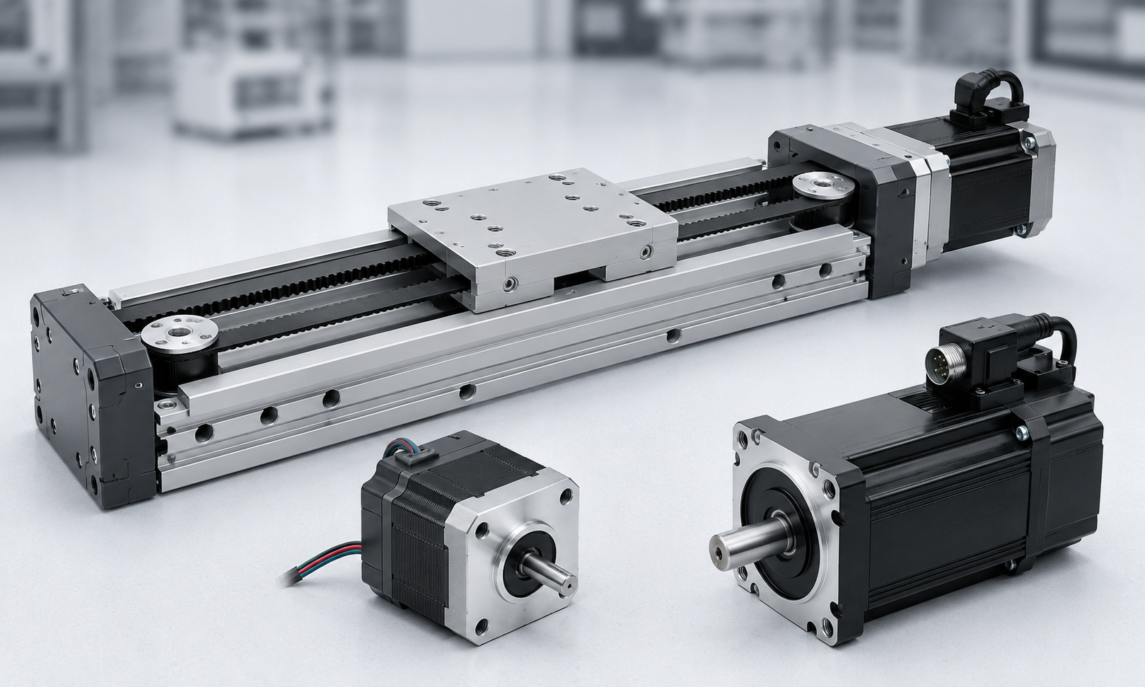
1. Main Parameters for Timing Belt Module Motor Selection
Before selecting a servo motor or stepper motor, the following application parameters should be confirmed:
- Payload and total moving mass
- Horizontal or vertical installation
- Required maximum speed
- Acceleration and deceleration time
- Effective travel distance
- Positioning and repeatability requirements
- Timing pulley pitch diameter
- Transmission ratio, if a gearbox is used
- Operating cycle and duty ratio
- External resistance and friction
- Available motor mounting space
- Whether a holding brake is required
The motor must provide sufficient speed and torque throughout the complete motion cycle. Checking only rated motor power is not enough because two motors with the same power may have very different rated torque, peak torque, rated speed and rotor inertia.
2. Servo Motor or Stepper Motor?
Servo motors and stepper motors can both be used with timing beltlinear modules, but they are suitable for different operating conditions.
| Selection Factor | Servo Motor | Stepper Motor |
|---|---|---|
| Control Method | Closed-loop control with encoder feedback | Usually open-loop or closed-loop step control |
| High-Speed Performance | Good torque performance at medium and high speeds | Torque decreases significantly as speed increases |
| Acceleration | Suitable for high acceleration and short cycle times | Better for moderate acceleration |
| Positioning Reliability | Encoder feedback detects position deviation | Open-loop systems may lose steps when overloaded |
| Operating Smoothness | Smooth operation across a wide speed range | May experience resonance at certain speeds |
| Cost | Higher motor, driver and commissioning cost | Lower system cost |
| Typical Applications | High-speed automation, frequent starts and stops, precision positioning | Light-load, low-speed and cost-sensitive applications |
When to Select a Servo Motor
A servo motor is normally recommended when thetiming belt modulerequires:
- High travel speed
- Rapid acceleration and deceleration
- Frequent reciprocating motion
- Short cycle times
- High positioning reliability
- Heavy or variable payloads
- Closed-loop position monitoring
- Multi-axis synchronization
When to Select a Stepper Motor
A stepper motor may be suitable when the application has:
- Relatively low speed
- Moderate acceleration
- Light and stable loads
- Simple point-to-point positioning
- Low operating frequency
- Strict cost limitations
For applications where lost steps cannot be accepted, a closed-loop stepper motor should be considered instead of a conventional open-loop stepper system.
3. Determine the Total Moving Mass
The moving mass is not limited to the workpiece. It should include all components that move with the timing belt carriage:
m = mpayload+ mcarriage+ mfixture+ mcable+ mother
Where:
mis the total moving mass in kilogramsmpayloadis the workpiece or product massmfixtureincludes grippers, tooling and mounting platesmcableincludes moving cables, hoses and cable carriers
Ignoring fixtures, cables or tooling can result in insufficient motor torque, especially during rapid acceleration.
4. Calculate the Required Linear Force
Horizontal Installation
For a horizontal timing belt module, the required linear force can be estimated using:
F = ma + Ff+ Fe
Where:
Fis the required linear force in newtonsmis the total moving mass in kilogramsais the required acceleration in metres per second squaredFfis the friction and transmission resistanceFeis any additional external force
At constant speed, acceleration is zero. The motor only needs to overcome friction and external resistance. During acceleration, however, the inertial force may become the largest part of the total load.
Vertical Installation
For upward vertical motion, gravity must be included:
F = m(g + a) + Ff+ Fe
Wheregis gravitational acceleration, approximately9.81 m/s².
For downward movement, the motor must control the gravitational load and decelerate the moving mass safely. Vertical applications may also produce regenerative energy, so the servo drive and braking resistor should be checked.
5. Calculate the Required Pulley Torque
After calculating the linear force, convert it into pulley torque:
Tpulley= F × r / h
Where:
Tpulleyis the required pulley torque in newton metresFis the required linear forceris the pulley pitch radius in metresoris the total mechanical transmission efficiency
The pitch radius, rather than the outside pulley radius, should be used in the calculation. The timing belt manufacturer or pulley drawing normally provides the pitch diameter.
If a gearbox is installed, the approximate motor torque is:
Tmotor= Tpulley/ (i × ng)
Where:
iis the speed reduction ratio, defined as motor speed divided by output speedorgis the gearbox efficiency
A gearbox reduces the motor torque requirement and increases the reflected load capacity, but it also reduces output speed and may introduce backlash.
6. Calculate the Required Motor Speed
The pulley rotational speed is determined by the required linear speed and pulley pitch diameter:
npulley= 60v / (πD)
Where:
npulleyis the pulley speed in revolutions per minutevis the required linear speed in metres per secondDis the pulley pitch diameter in metres
When a gearbox is used:
nmotor= npulley× i
The calculated motor speed should remain within the continuous operating speed range of the selected motor. A motor should not be selected only because its maximum speed is higher than the calculated value. Its available torque at that speed must also be verified from the motor torque-speed curve.
7. Check Load Inertia
Load inertia affects acceleration response, positioning stability and servo tuning. For a direct-drive timing pulley, the equivalent inertia of the moving mass can be approximated by:
Jlinear= mr²
The complete load inertia should also include:
- Drive pulley inertia
- Driven pulley inertia
- Timing belt inertia
- Coupling inertia
- Gearbox output inertia
- Other rotating components
If a gearbox is used, the load inertia reflected to the motor shaft is:
Jreflected= Jload/ i²
The inertia ratio can then be calculated as:
Inertia ratio = Jreflected/ Jmotor
A lower inertia ratio generally provides easier servo tuning and faster response. The acceptable ratio depends on the servo system, machine rigidity, motion profile and control requirements. The motor manufacturer's recommended inertia ratio should always be checked.
8. Check Acceleration Torque
The motor must accelerate both the linear load and the rotating components. The rotational acceleration torque is:
Tacc= Jtotal× a
Where:
Jtotalis the total inertia reflected to the motor shaftais the angular acceleration in radians per second squared
The motor peak torque should be greater than the total torque required during acceleration:
Tpeak required= Tload+ Tacc
For aggressive motion profiles, acceleration torque may be much higher than the torque required during constant-speed travel.
9. Check Continuous Torque, Peak Torque and Motor Power
Three different motor capabilities should be checked:
Continuous Torque
Continuous torque determines whether the motor can operate without overheating during repeated cycles. It should be checked using the root mean square torque of the complete cycle:
TRMS= √[(T₁²t₁ + T₂²t₂ + ... + Tₙ²tₙ) / (t₁ + t₂ + ... + tₙ)]
The calculated RMS torque should remain below the motor's rated continuous torque.
Peak Torque
Peak torque is required during acceleration, deceleration, emergency stopping or temporary external loading. The required peak torque must remain below the motor's allowable instantaneous torque.
Motor Power
The mechanical power can be estimated using either linear force or rotational torque:
P = Fv / η
or:
P = To
Motor power is useful for preliminary selection, but final sizing should be based on torque, speed, inertia and duty cycle. Two motors with the same rated power may not provide the same peak torque or dynamic response.
10. Select a Suitable Safety Factor
A safety factor is normally applied to compensate for calculation uncertainty, load variation, friction changes and long-term wear.
For stable horizontal applications, a torque safety factor of approximately1.3 to 1.5may be used as an initial reference. Higher margins may be required for:
- Vertical axes
- High acceleration
- Frequent starts and stops
- Impact or variable loads
- Uncertain friction
- Long-term continuous operation
- Harsh operating environments
An excessively large safety factor should also be avoided because an oversized motor may increase rotor inertia and reduce dynamic performance.
11. Brake Motor Selection for Vertical Axes
A motor with an electromagnetic holding brake is strongly recommended when the timing belt linear module is installed vertically or at an incline where the load can fall after power is removed.
The brake is mainly used to hold the axis when the machine is stopped or power is lost. It should not normally be used as a dynamic stopping brake during every motion cycle.
For a vertical axis, check that:
- The brake holding torque is higher than the static gravitational torque
- The brake includes an appropriate safety margin
- The control sequence engages the brake only after the motor has stopped
- The motor produces holding torque before the brake is released
- The servo drive can manage regenerative energy during downward motion
- A counterbalance or gas spring is considered for heavy loads
For safety-critical vertical systems, mechanical locking devices, anti-fall mechanisms or redundant protection may also be required.
12. Motor Mounting Direction
Timing belt linear modules can support different motor mounting arrangements depending on the available machine space.
| Mounting Direction | Characteristics | Typical Use |
|---|---|---|
| Direct In-Line Mounting | Motor shaft is connected directly to the drive pulley through a coupling | Simple structure and high transmission efficiency |
| Left-Side Mounting | Motor is positioned beside the module using a belt or gearbox transmission | Machines with limited axial installation space |
| Right-Side Mounting | Mirror arrangement of left-side mounting | Selected according to cable routing and machine layout |
| Bottom or Folded Mounting | Motor is installed under or parallel to the module | Compact equipment and enclosed machinery |
Motor mounting direction normally does not change the basic linear force requirement, but additional pulleys, belts or gearboxes affect transmission ratio, efficiency, backlash and rotational inertia. These components must be included in the motor calculation.
13. Timing Belt Module Motor Selection Example
Consider a horizontal timing belt linear module with the following conditions:
- Total moving mass:
35 kg - Required maximum speed:
1.5 m/s - Required acceleration:
4 m/s² - Estimated friction and external resistance:
25 N - Pulley pitch diameter:
60 mm - Transmission efficiency:
92% - Direct-drive motor connection
Step 1: Calculate Linear Force
F = ma + Ff
F = 35 × 4 + 25 = 165 N
Step 2: Calculate Pulley Torque
The pulley pitch radius is:
r = 0.06 / 2 = 0.03 m
T = 165 × 0.03 / 0.92 ≈ 5.38 N·m
This value represents the approximate torque required at the pulley during acceleration before adding the inertia of rotating components and a safety margin.
Step 3: Calculate Pulley Speed
n = 60 × 1.5 / (π × 0.06)
n ≈ 477 rpm
Step 4: Estimate Mechanical Power
P = Fv / η
P = 165 × 1.5 / 0.92 ≈ 269 W
The calculated power does not directly determine the final motor rating. The selected motor must also satisfy the required peak torque, RMS torque, rotor inertia, cycle time and torque available at approximately477 rpm.
For this application, a servo motor would generally be more suitable than an open-loop stepper motor because the axis requires relatively high acceleration and reliable torque during repeated motion. The final motor model should be confirmed using the manufacturer's torque-speed curve and inertia recommendations.
14. Common Motor Selection Mistakes
Selecting the Motor Only by Rated Power
Rated power alone does not confirm that the motor can provide sufficient peak torque or operate at the required speed.
Ignoring the Carriage and Fixture Mass
Only using the payload mass underestimates the total acceleration force.
Ignoring Stepper Motor Torque Reduction
A stepper motor may provide high holding torque at zero speed but much lower torque at the actual operating speed.
Using Maximum Motor Torque as Continuous Torque
Peak torque is available only for a limited time. Repeated use may cause overheating or drive alarms.
Ignoring Load Inertia
Excessive inertia mismatch can cause poor response, vibration, overshoot and difficult servo tuning.
Ignoring Vertical Gravity Load
Vertical axes require additional torque to overcome gravity and usually require a holding brake.
Ignoring the Complete Motion Cycle
Acceleration time, constant-speed time, deceleration time, dwell time and cycle frequency all affect RMS torque and motor temperature.
15. Motor Selection Checklist
Before confirming a timing belt linear module motor, verify the following:
- The maximum motor speed is higher than the calculated operating speed
- The motor torque-speed curve satisfies the required operating point
- The rated torque is higher than the calculated RMS torque
- The peak torque is higher than the acceleration and deceleration torque
- The load inertia ratio is within the recommended range
- The motor and driver support the required duty cycle
- The motor mounting direction fits the machine layout
- The coupling, gearbox and pulley match the motor shaft
- The brake torque is sufficient for vertical installation
- The servo drive can manage regenerative energy
- Cables and connectors meet the required bending and environmental conditions
- An appropriate safety factor has been included
Frequently Asked Questions
How much motor power does a timing belt linear module need?
The required power depends on moving mass, speed, acceleration, pulley diameter, efficiency and duty cycle. Power can be estimated usingP = Fv / η, but final selection must also verify continuous torque, peak torque, motor speed and load inertia.
Is a servo motor better than a stepper motor for a timing belt module?
A servo motor is generally better for high speed, rapid acceleration, frequent cycles and high positioning reliability. A stepper motor can be economical for low-speed, light-load and less demanding applications.
Does a larger motor always improve performance?
No. An oversized motor increases cost, weight and rotor inertia. Excessive motor inertia can reduce acceleration response and make system tuning more difficult.
Does a vertical timing belt module require a brake motor?
A holding brake is strongly recommended when gravity can cause the load to fall after power loss. Safety-critical systems may also require mechanical anti-fall protection.
Can a gearbox be used with a timing belt linear module?
Yes. A gearbox can increase output torque and reduce reflected load inertia, but it also changes output speed, efficiency, backlash and overall system inertia.
Conclusion
Motor selection for a timing belt linear module should be based on the complete mechanical and motion requirements. The selection process includes calculating moving mass, linear force, pulley torque, motor speed, load inertia, acceleration torque, RMS torque and peak torque.
Servo motors are normally preferred for high-speed, high-acceleration and high-reliability automation. Stepper motors remain suitable for simpler, lower-speed and cost-sensitive applications. Vertical axes should use a properly sized holding brake and may require additional anti-fall or counterbalance mechanisms.
Final motor selection should always be verified against the motor manufacturer's torque-speed curve, allowable inertia ratio, duty cycle and thermal limits.
