 English

Selecting aball screw linear modulerequires more than comparing maximum load and stroke specifications. The correct model must satisfy the application's load, travel, speed, positioning accuracy, installation orientation, motor capacity and operating environment at the same time.
An oversized module may increase equipment cost and moving mass, while an undersized module can cause excessive vibration, positioning errors, premature ball screw wear or motor overload. A systematic selection process helps balance performance, reliability and cost.
This guide explains how to choose a ball screw linear module by evaluating application requirements, load capacity, stroke, screw diameter, lead, speed, accuracy, installation orientation, motor selection and environmental conditions.
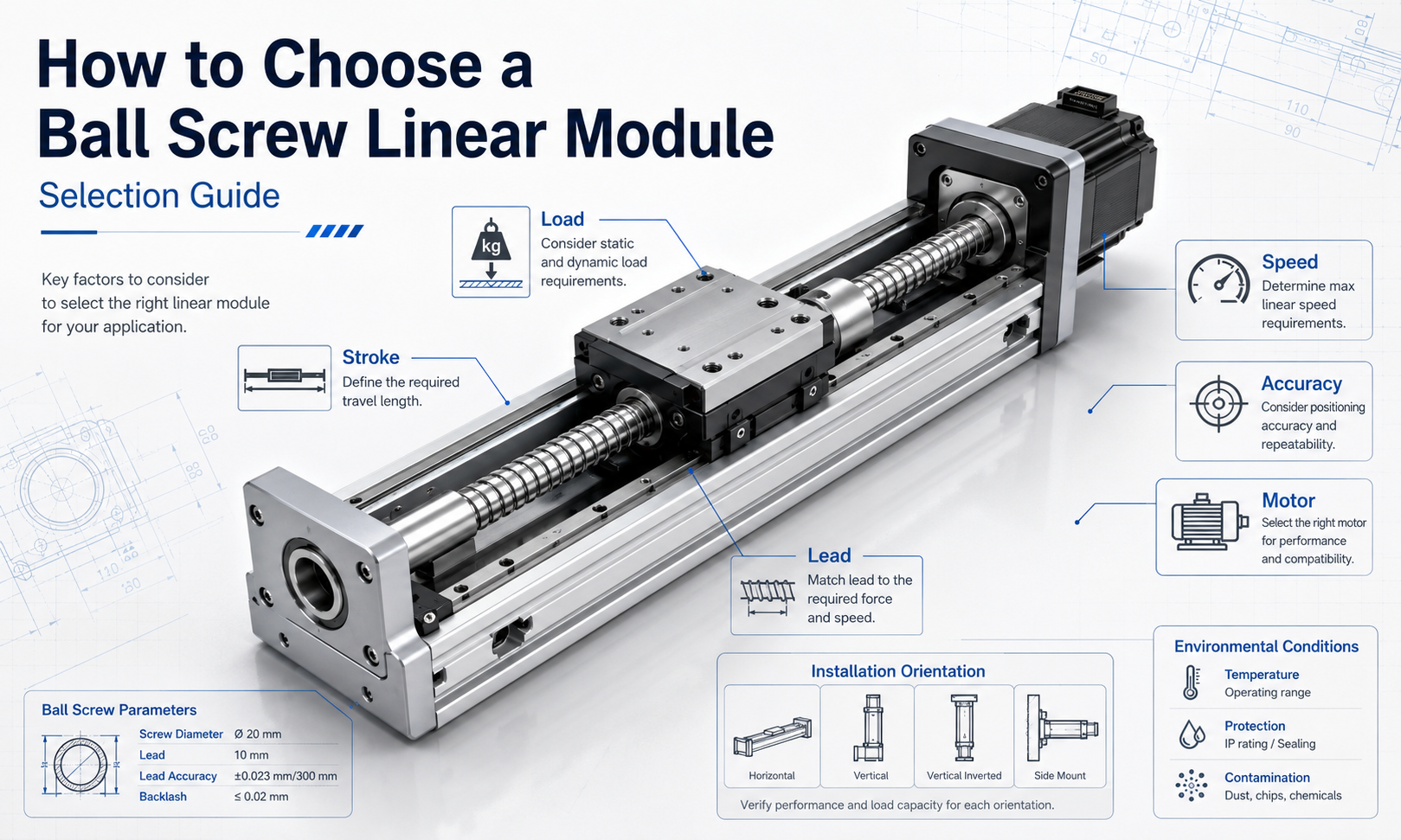
1. Define the Application Requirements
The first step is to clearly define what thelinear modulemust accomplish. Selection should begin with the actual motion cycle rather than a preferred module size or motor model.
Collect the following application information:
- Workpiece, fixture and tooling weight
- Required effective stroke
- Horizontal, vertical or inclined installation
- Maximum operating speed
- Acceleration and deceleration
- Required positioning accuracy
- Required repeatability
- Cycle time and daily operating hours
- External forces acting on the carriage
- Radial, pitch, yaw and roll moments
- Available installation space
- Motor and controller requirements
- Temperature, dust, moisture and cleanroom conditions
A complete motion profile should include travel distance, acceleration time, constant-speed time, deceleration time and dwell time. These parameters determine the required motor speed, torque and ball screw operating speed.
2. Calculate the Total Moving Load
The total moving load is not limited to the workpiece. It includes every component mounted on the carriage.
The moving mass may include:
- Workpiece
- Fixture or pallet
- Gripper or end effector
- Sensor bracket
- Secondary-axis module
- Motor or gearbox mounted on the moving axis
- Cables and cable carrier forces
The basic acceleration force can be estimated as:
F = m × a
Where:
- Fis the acceleration force in newtons
- mis the total moving mass in kilograms
- ais the acceleration in metres per second squared
For a horizontal installation, the ball screw mainly overcomes acceleration force, friction and external process forces.
For a vertical installation, the drive must also overcome gravity:
Fvertical= m × g + m × a + Ffriction+ Fexternal
For downward acceleration, gravity may assist the motion, but the motor and brake must still control the load safely during deceleration and power loss.
Apply an Appropriate Safety Factor
The calculated thrust should not be equal to the module's maximum rated thrust. A safety factor is needed to account for load variation, impact, assembly deviation and unexpected resistance.
For stable, low-impact applications, a safety factor of approximately 1.5 to 2.0 is commonly considered. Applications involving shock loads, high acceleration, frequent starts and stops or uncertain external forces may require a higher factor.
Always verify both the module's allowable payload and the ball screw's dynamic load rating.
3. Evaluate Moment Loads
A linear module carriage can be subjected to more than a direct vertical load. An offset load creates moment forces that act on the linear guide and carriage.
The main moment directions include:
- Pitch moment:rotation around the transverse axis
- Yaw moment:rotation around the vertical axis
- Roll moment:rotation around the travel axis
A simplified moment calculation is:
M = F × L
Where:
- Mis the applied moment
- Fis the applied force
- Lis the distance between the force and the carriage centre
Even a moderate load can generate a large moment when mounted far from the carriage centre. Therefore, payload capacity alone is not sufficient for module selection.
When the applied moment approaches the module's allowable limit, consider:
- Increasing the carriage length
- Using a wider module
- Installing two parallel modules
- Reducing the load offset
- Adding an external support guide
4. Determine the Required Stroke
The specified stroke should be based on the actual working travel plus the additional distance required for safe operation.
The required module stroke may include:
- Effective process travel
- Loading and unloading clearance
- Sensor activation distance
- Acceleration and deceleration distance
- Mechanical safety margin
- Home-position allowance
A module should not be selected with its carriage operating continuously against the mechanical end limits. Reserve suitable travel at both ends for limit sensors, emergency deceleration and installation adjustment.
Stroke Is Not the Same as Overall Length
The total module length is greater than the effective stroke because the body must accommodate the carriage, bearing supports, motor mount and end structures.
Before confirming the stroke, verify:
- Total module length
- Motor extension length
- Coupling and motor-mount dimensions
- Cable carrier bending space
- Maintenance and lubrication access
5. Select the Ball Screw Diameter
Ball screw diameter affects thrust capacity, rigidity, critical speed, buckling resistance and service life. A larger screw diameter generally provides greater axial rigidity and supports higher loads, but it also increases rotating inertia, module size and cost.
The screw diameter should be selected according to:
- Axial load
- Module stroke
- Maximum rotational speed
- Installation orientation
- Required rigidity
- Support-bearing arrangement
- Expected service life
Long-Stroke Applications
As the screw becomes longer, its critical rotational speed decreases. If the screw rotates too quickly, it may produce vibration, noise and whipping.
For a long stroke, the designer may need to:
- Use a larger screw diameter
- Select a larger lead to reduce screw speed
- Reduce the maximum linear speed
- Improve the screw support arrangement
- Use a fixed-fixed bearing configuration
- Consider another transmission method for very long travel
Vertical Applications
Vertical installations place a continuous axial load on the ball screw. The screw diameter and ball nut load rating must support the suspended mass while maintaining adequate safety against buckling and unexpected downward movement.
6. Choose the Correct Ball Screw Lead
Ball screw lead is the linear distance travelled by the nut during one screw revolution. Lead directly affects speed, thrust, motor torque, resolution and control performance.
The relationship between linear speed, screw lead and rotational speed is:
n = v × 60 ÷ L
Where:
- nis the screw speed in revolutions per minute
- vis the linear speed in millimetres per second
- Lis the screw lead in millimetres per revolution
For example, when the required linear speed is 500 mm/s and the screw lead is 10 mm:
n = 500 × 60 ÷ 10 = 3000 rpm
Small-Lead Ball Screws
A smaller lead generally provides:
- Higher mechanical advantage
- Greater thrust for the same motor torque
- Finer theoretical movement per motor revolution
- Better low-speed control
However, a small lead requires a higher screw rotational speed to achieve the same linear speed.
Large-Lead Ball Screws
A larger lead generally provides:
- Higher linear speed at a lower screw speed
- Lower risk of exceeding the screw's critical speed
- Shorter cycle times for long travel
However, a larger lead requires more motor torque for the same axial thrust and provides greater linear movement per motor revolution.
Lead Selection Balance
The correct lead should balance:
- Required speed
- Required thrust
- Motor rated speed
- Motor torque
- Positioning resolution
- Critical screw speed
- Acceleration performance
7. Verify the Maximum Speed
Maximum module speed is limited by more than the motor's maximum rotational speed. The complete system must remain within the allowable operating range of the ball screw, bearings, coupling, linear guide and lubrication system.
Check the following limits:
- Ball screw critical speed
- Ball screw permissible rotational speed
- Motor rated and maximum speed
- Coupling allowable speed
- Bearing allowable speed
- Linear guide operating speed
- Lubrication condition
- Noise and vibration requirements
A module should not operate continuously at its theoretical maximum specification. Selecting a reasonable operating margin improves stability and service life.
Acceleration and Cycle Time
High speed alone does not guarantee a short cycle time. On a short stroke, the module may not have enough distance to reach its maximum speed.
The motion cycle should be evaluated using:
- Acceleration time
- Constant-speed travel time
- Deceleration time
- Settling time
- Process dwell time
- Return travel time
For short, high-frequency movements, acceleration capability and settling behaviour may be more important than maximum speed.
8. Define the Required Accuracy
Accuracy specifications should be based on the actual process requirement. Selecting unnecessarily high accuracy can increase cost without improving production performance.
Important accuracy terms include:
Positioning Accuracy
Positioning accuracy describes the difference between the commanded position and the actual position over the module's travel.
Repeatability
Repeatability describes the module's ability to return to the same position repeatedly under the same operating conditions.
Backlash
Backlash is lost motion that may occur when the travel direction reverses. Preloaded ball nuts can reduce axial clearance and improve reversing performance.
Resolution
Resolution is the smallest theoretical movement that can be commanded by the motor and control system. It depends on screw lead, encoder resolution and electronic interpolation.
High command resolution does not automatically guarantee high positioning accuracy. Actual accuracy is also affected by:
- Ball screw lead error
- Backlash
- Guide straightness
- Mounting-surface accuracy
- Structural deformation
- Thermal expansion
- Coupling alignment
- Encoder performance
- Controller tuning
Match Accuracy to the Process
| Application | Main Selection Priority |
|---|---|
| General material handling | Repeatability, reliability and load capacity |
| Vision inspection | Smooth motion, repeatability and settling stability |
| Precision dispensing | Path accuracy, low-speed stability and repeatability |
| Semiconductor equipment | Precision, cleanliness, rigidity and thermal stability |
| Laser processing | Trajectory accuracy, speed stability and rigidity |
| Measurement equipment | Positioning accuracy, straightness and error compensation |
9. Consider the Installation Orientation
Installation orientation changes the load acting on the ball screw, guides and motor.
Horizontal Installation
In a horizontal configuration, the linear guide supports the weight while the ball screw mainly provides acceleration and process thrust. This is generally the least demanding orientation for the drive system.
Vertical Installation
In a vertical configuration, the motor must continuously overcome gravity. Selection should consider:
- Continuous lifting torque
- Peak acceleration torque
- Motor brake
- Emergency stopping
- Power-loss protection
- Ball screw buckling resistance
- Counterbalance requirements
A brake-equipped motor is normally considered when an uncontrolled downward movement could create equipment damage or a safety risk.
Side-Mounted Installation
When the module is mounted on its side, the load direction relative to the guide blocks changes. Verify the allowable load and moment ratings for the actual installation direction.
Inclined Installation
An inclined axis combines horizontal and vertical force components. The gravitational force along the travel direction can be estimated according to the installation angle and must be included in the thrust calculation.
10. Select the Motor
The motor must provide sufficient speed, continuous torque, peak torque and acceleration capacity for the entire motion cycle.
Motor selection should include:
- Maximum rotational speed
- Continuous operating torque
- Peak acceleration torque
- Load inertia
- Ball screw rotational inertia
- Coupling efficiency
- Vertical gravity load
- Friction and external resistance
- Duty cycle
- Holding brake requirements
Estimate the Drive Torque
The torque required to generate axial force through a ball screw can be estimated as:
T = F × L ÷ (2π × η)
Where:
- Tis the required torque
- Fis the axial force
- Lis the ball screw lead
- oris the ball screw transmission efficiency
The total motor torque should also include acceleration torque for the moving mass and rotating components.
Check Motor Speed
The required motor speed is determined by the target linear speed and screw lead. The motor should be able to maintain the required operating speed without continuously running at its absolute maximum limit.
Check Inertia Matching
A high load-to-motor inertia ratio can make servo tuning difficult and reduce response stability. When inertia is excessive, possible solutions include:
- Using a larger motor
- Reducing acceleration
- Changing the ball screw lead
- Adding a gearbox
- Reducing the moving mass
Servo Motor or Stepper Motor
| Selection Factor | Servo Motor | Stepper Motor |
|---|---|---|
| Speed range | Suitable for higher speed and wider speed variation | More suitable for low- to medium-speed motion |
| Feedback | Closed-loop encoder feedback | Commonly open-loop or closed-loop depending on configuration |
| Acceleration | Better suited to high acceleration and dynamic cycles | Suitable for moderate acceleration |
| Load variation | Better adaptability to changing loads | Requires careful torque margin |
| Cost | Generally higher | Generally lower |
| Typical use | Precision automation and high-speed production | Simple positioning and cost-sensitive equipment |
11. Evaluate Environmental Conditions
The operating environment affects module sealing, lubrication, material selection and service life.
Dust and Particles
Dust can enter the ball screw raceway and linear guide, causing wear and unstable motion. Protective covers, bellows, seals or fully enclosed module designs may be required.
Moisture and Corrosive Conditions
Humid, washdown or chemically aggressive environments may require:
- Corrosion-resistant components
- Special surface treatment
- Sealed bearings
- Water-resistant sensors
- Suitable protective covers
- Environment-compatible lubricant
Cleanroom Applications
Cleanroom equipment may require low-particle materials, controlled lubrication, enclosed transmission components and compatible cable management.
High or Low Temperature
Temperature changes can affect lubricant viscosity, component clearance, sensor reliability and thermal expansion. Precision applications should evaluate the effect of temperature on positioning accuracy.
Vacuum Applications
Vacuum environments require compatible grease, materials, cables and surface treatments. Standard modules should not be assumed suitable without confirmation.
12. Check Module Rigidity and Mounting Accuracy
A high-precision ball screw cannot compensate for a weak machine frame or an uneven mounting surface.
The mounting structure should provide:
- Sufficient flatness
- Adequate structural rigidity
- Secure fastening points
- Correct alignment
- Resistance to vibration
- Thermal stability
When two modules are installed in parallel, alignment becomes especially important. Misalignment can create additional friction, uneven guide loading and premature wear.
13. Verify Service Life and Duty Cycle
Ball screw and linear guide life depend on load magnitude, load direction, speed, acceleration, lubrication and operating frequency.
Selection should consider:
- Number of cycles per minute
- Operating hours per day
- Expected equipment service life
- Average and peak load
- Impact and vibration
- Lubrication interval
- Maintenance accessibility
A module that meets the maximum-load requirement may still be unsuitable for continuous high-frequency operation if its calculated fatigue life is insufficient.
14. Ball Screw Linear Module Selection Example
Consider a horizontal positioning application with the following requirements:
- Total moving mass: 35 kg
- Effective stroke: 800 mm
- Maximum speed: 600 mm/s
- Acceleration: 3 m/s²
- Required repeatability: ±0.02 mm
- Installation: horizontal
- Operation: frequent reciprocating movement
The basic acceleration force is:
F = 35 × 3 = 105 N
Additional friction, cable resistance and process forces must then be added. After applying an appropriate safety factor, the required thrust can be used to select the ball screw and motor.
If a 10 mm lead is selected, the screw speed at 600 mm/s is:
n = 600 × 60 ÷ 10 = 3600 rpm
The designer must verify that this speed is below the permissible ball screw speed and critical speed for the selected screw diameter and stroke.
If the screw speed is too high, possible adjustments include:
- Using a larger lead
- Increasing the screw diameter
- Reducing the maximum speed
- Changing the support-bearing configuration
The final selection must also confirm guide moment capacity, motor peak torque, duty cycle, module length and installation-space requirements.
15. Ball Screw Linear Module Selection Checklist
| Selection Item | Information to Confirm |
|---|---|
| Application | Positioning, dispensing, inspection, assembly, machining or handling |
| Moving mass | Workpiece, fixture, tooling, secondary axis and cable forces |
| External force | Process force, friction, impact and resistance |
| Moment load | Pitch, yaw and roll moments caused by load offset |
| Stroke | Effective travel plus sensor and safety allowance |
| Speed | Maximum and normal operating speed |
| Acceleration | Acceleration, deceleration and emergency stopping requirements |
| Ball screw diameter | Load, rigidity, buckling and critical-speed requirements |
| Ball screw lead | Speed, thrust, resolution and motor-speed balance |
| Accuracy | Positioning accuracy, repeatability, backlash and resolution |
| Installation orientation | Horizontal, vertical, side-mounted or inclined |
| Motor | Rated speed, continuous torque, peak torque, inertia and brake |
| Environment | Dust, moisture, temperature, cleanroom, vacuum and corrosion |
| Duty cycle | Cycles per minute, working hours and expected service life |
| Installation space | Overall length, motor position, cable carrier and maintenance access |
Common Ball Screw Linear Module Selection Mistakes
- Selecting a module only according to payload
- Ignoring moment loads caused by an offset fixture
- Using effective stroke as the total installation length
- Selecting a small lead without checking screw rotational speed
- Selecting a large lead without checking motor torque
- Ignoring critical speed in long-stroke applications
- Using horizontal-load data for a vertical installation
- Ignoring acceleration and deceleration torque
- Confusing encoder resolution with actual positioning accuracy
- Installing a precision module on an inaccurate mounting surface
- Operating continuously at maximum catalogue specifications
- Ignoring dust protection and lubrication requirements
Conclusion
Choosing a ball screw linear module requires a complete evaluation of the mechanical load, motion profile, stroke, screw diameter, lead, speed, accuracy, installation orientation, motor and operating environment.
Begin with the application's actual moving mass, external forces and moment loads. Then calculate the required thrust, determine the stroke, select an appropriate screw diameter and lead, and verify screw speed, critical speed and motor capacity. Finally, confirm accuracy, mounting conditions, environmental protection, duty cycle and service-life requirements.
A properly selected ball screw linear module provides stable positioning, smooth motion, sufficient rigidity and reliable long-term operation without unnecessary oversizing.
