 English

Aball screw linear moduleis a precision linear motion device that converts the rotary movement of a motor into controlled linear movement. The conversion is achieved through the interaction between a ball screw shaft, a ball nut and a series of recirculating steel balls.
Unlike an ordinary sliding screw, a ball screw uses rolling contact between the screw and nut. This rolling mechanism significantly reduces friction, improves transmission efficiency and allows the module to achieve high positioning accuracy, smooth movement and reliable repeatability.
However, the completeball screw linear module working principleinvolves more than the screw and nut alone. The motor, coupling, bearing supports, linear guide, carriage, preload system, servo controller and position feedback device all work together to form a controlled linear motion system.
This article explains how aball screw linear moduleconverts motor rotation into precise linear movement, how the recirculating ball mechanism operates and how servo control and position feedback improve positioning performance.
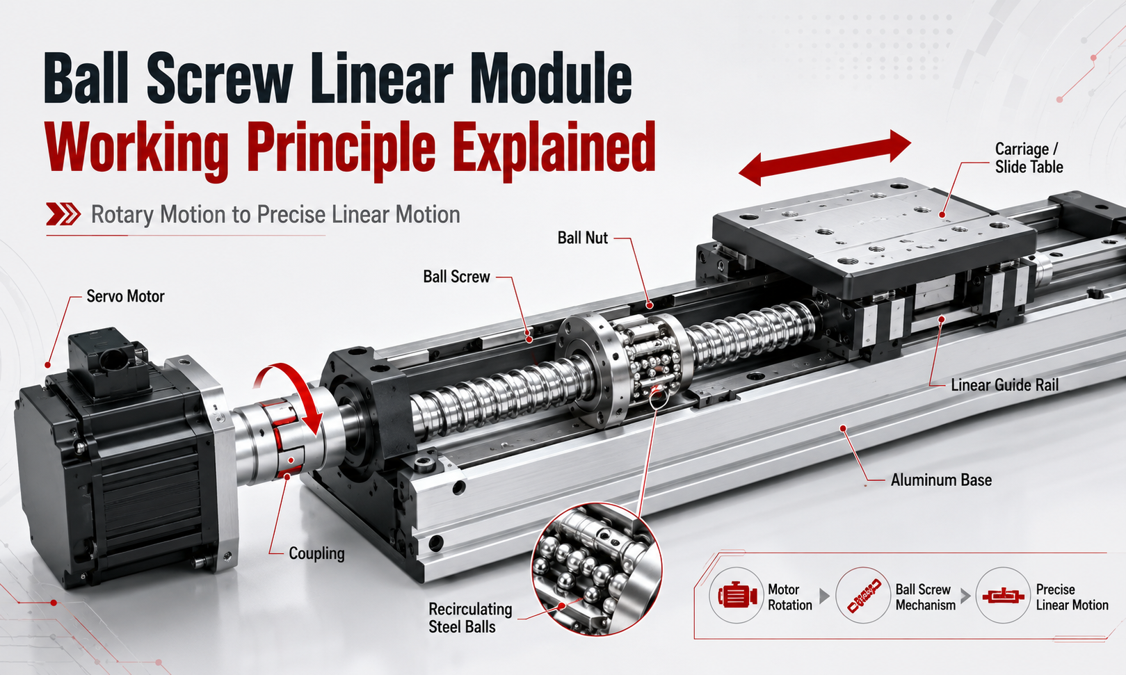
What Is the Basic Working Principle of a Ball Screw Linear Module?
The basic working principle of a ball screw linear module can be summarized as follows:
- The controller sends a motion command to the servo motor or stepper motor.
- The motor generates rotary movement and torque.
- The coupling transfers the motor rotation to the ball screw shaft.
- The ball screw rotates inside the ball nut.
- The recirculating balls roll between the screw grooves and nut grooves.
- The ball nut moves axially along the rotating screw.
- The carriage connected to the nut moves along the linear guide.
- The encoder or linear scale measures the actual movement position.
- The controller compares the commanded position with the actual position and corrects any deviation.
In most ball screwlinear modules, the screw shaft rotates while the ball nut is prevented from rotating. Because the nut cannot rotate, the helical geometry of the screw forces the nut to move in a straight line along the screw axis.
The carriage is mechanically connected to the ball nut. As a result, the axial movement of the nut becomes the linear movement of the carriage and the load mounted on it.
Rotary-to-Linear Motion Conversion
The central function of a ball screw drive mechanism is to convert motor rotation into linear displacement.
A servo motor normally produces rotary motion. This rotary movement alone cannot directly move a workpiece along a straight path. The ball screw therefore acts as a mechanical motion converter.
The surface of the ball screw contains a precisely machined helical groove. A matching groove is formed inside the ball nut. Together, these grooves create a helical raceway for the steel balls.
When the screw rotates, the balls roll along the helical raceway. Because the nut is constrained against rotation, the rolling movement generates an axial force that moves the nut forward or backward.
The direction of linear movement depends on the direction of screw rotation:
- When the motor rotates clockwise, the carriage moves in one direction.
- When the motor rotates counterclockwise, the carriage moves in the opposite direction.
The exact direction depends on the thread orientation, motor installation and coordinate definition of the machine.
How the Ball Screw and Nut Work Together
The ball screw shaft and ball nut are the primary transmission components inside the linear module.
The screw shaft provides the rotating helical track, while the nut supports the recirculating balls and converts their rolling movement into axial displacement. The screw groove, nut groove and balls must have carefully controlled geometry to achieve smooth and accurate transmission.
When torque is applied to the screw, the contact force passes through the following transmission path:
Motor → Coupling → Ball Screw → Steel Balls → Ball Nut → Carriage → Load
The balls transfer force between the screw and the nut through rolling contact. Because the balls roll instead of slide, the friction coefficient is much lower than that of a conventional lead screw.
This enables a ball screw linear module to provide:
- High mechanical transmission efficiency
- Low starting resistance
- Smooth low-speed movement
- Accurate bidirectional positioning
- Reduced wear between the screw and nut
- Long operating life under proper lubrication
The ball nut is normally connected to the moving carriage through a nut housing or mounting block. This connection must have sufficient rigidity so that the axial force generated by the nut can be transferred to the carriage without excessive deformation.
How the Recirculating Ball Mechanism Works
The recirculating ball mechanism is the defining feature of a ball screw.
Steel balls are positioned between the helical grooves of the screw and nut. As the screw rotates, the balls roll through the loaded contact zone and transfer axial force between the two components.
If the balls were allowed to continue moving along the helical groove without returning, they would eventually leave the nut. A return system is therefore used to continuously circulate the balls.
The circulation process can be divided into four stages:
- The balls enter the loaded raceway between the screw and nut.
- They roll through the contact zone while transmitting force.
- At the end of the circulation path, a return component guides the balls away from the loaded groove.
- The balls travel through the return passage and re-enter the beginning of the raceway.
This creates a closed circulation loop. The same balls continuously move through the load-bearing raceway and return path during operation.
Common recirculation structures include:
- End cap circulation
- Return tube circulation
- Internal deflector circulation
- End deflector circulation
Each circulation design has different characteristics in terms of nut dimensions, operating noise, permissible speed, manufacturing complexity and load capacity.
Smooth ball circulation is essential for reliable operation. Contamination, insufficient lubrication, damaged return components or incorrect assembly can interrupt the ball path and cause abnormal noise, vibration, increased friction or premature failure.
Rolling Contact and Transmission Efficiency
A traditional sliding screw relies on sliding friction between the screw thread and nut thread. In contrast, a ball screw replaces most of this sliding contact with rolling contact.
This difference allows ball screws to achieve high mechanical efficiency. Depending on the design and operating conditions, ball screw transmission efficiency can commonly exceed 85% and may approach or exceed 90%.
High efficiency provides several practical advantages:
- More motor torque is converted into useful axial thrust.
- A smaller motor may be used for the same load requirement.
- Less energy is lost as frictional heat.
- Movement is smoother at low speed.
- Direction reversal requires less breakaway force.
High efficiency also means that many ball screws are not self-locking. When the motor is powered off, a vertical load may drive the screw backward and cause the carriage to fall.
Vertical ball screw modules may therefore require a motor brake, mechanical locking device, counterbalance mechanism or other safety measure.
Lead and Pitch in Ball Screw Motion
Ball screw lead is one of the most important parameters affecting the movement of a ball screw linear module.
Leadrefers to the axial distance the ball nut travels when the screw completes one full revolution.
For example, if a ball screw has a lead of 10 millimeters, one complete revolution of the screw moves the nut approximately 10 millimeters along the axis.
The basic relationship is:
Linear travel = Number of screw revolutions × Ball screw lead
If a 10-millimeter-lead ball screw rotates five revolutions, the theoretical linear travel is:
5 × 10 mm = 50 mm
Pitchis the axial distance between corresponding points on adjacent threads. On a single-start screw, the lead is equal to the pitch. On a multi-start screw, the lead equals the pitch multiplied by the number of thread starts.
The selected lead directly affects speed, thrust and positioning resolution.
Small-Lead Ball Screws
A smaller lead provides less linear movement per motor revolution. It is generally suitable for applications requiring:
- Fine positioning resolution
- High axial thrust
- Stable low-speed movement
- Precise short-stroke positioning
However, a smaller lead requires more screw revolutions to achieve the same linear travel, which can limit maximum linear speed.
Large-Lead Ball Screws
A larger lead produces more linear movement per motor revolution. It is generally suitable for applications requiring:
- Higher linear speed
- Faster cycle times
- Longer travel within a limited motor speed range
However, a larger lead usually provides lower mechanical advantage and may reduce theoretical positioning resolution when the same motor and encoder are used.
How Ball Screw Lead Affects Speed
The theoretical linear speed of a ball screw module can be calculated from the screw speed and lead:
Linear speed = Screw rotational speed × Ball screw lead
For example, if a ball screw with a 10-millimeter lead rotates at 2,000 revolutions per minute, the theoretical linear speed is:
2,000 × 10 mm = 20,000 mm/min
This is equivalent to approximately 333 millimeters per second.
Actual permissible speed may be lower because of screw critical speed, bearing capacity, nut circulation speed, vibration, lubrication condition and the total stroke length.
For long-stroke modules, the screw diameter, unsupported length and support arrangement must be carefully evaluated. Excessive rotational speed can cause screw whipping, vibration and positioning instability.
How Ball Screw Lead Affects Thrust
Motor torque is converted into axial thrust through the helical geometry of the ball screw.
For the same motor torque, a smaller screw lead generally produces greater axial thrust, while a larger lead produces higher linear speed.
The approximate relationship can be expressed as:
Axial thrust = Motor torque × 2π × Transmission efficiency ÷ Ball screw lead
This relationship explains why ball screw lead selection requires a balance between speed and thrust.
An engineer should not select the lead based only on the desired travel speed. Load mass, acceleration, external process force, friction, installation orientation and safety factor must also be considered.
What Is Ball Screw Preload?
Preload is an internal force intentionally applied between the screw, balls and nut to reduce or eliminate axial clearance.
Without preload, a small clearance may exist between the rolling elements and the raceways. When the direction of movement changes, the screw may rotate slightly before the nut begins moving in the opposite direction. This lost motion is commonly associated with backlash.
Preload keeps the balls in controlled contact with both sides of the raceway. This improves the relationship between screw rotation and nut displacement, especially during bidirectional positioning.
Common preload methods include:
- Double-nut preload
- Oversized-ball preload
- Offset-pitch preload
- Groove geometry preload
Advantages of Preload
- Reduced axial backlash
- Improved positioning repeatability
- Greater axial rigidity
- More stable direction reversal
- Better response during acceleration and deceleration
Trade-Offs of Excessive Preload
More preload does not always mean better performance. Excessive preload can increase:
- Frictional resistance
- Motor torque demand
- Operating temperature
- Lubrication requirements
- Raceway contact stress
- Risk of premature wear
The appropriate preload should therefore be selected according to the required accuracy, rigidity, speed, duty cycle and expected service life.
The Role of the Linear Guide System
The ball screw generates and transmits axial force, but it should not be used as the primary component for supporting radial loads, overturning moments or external side forces.
The linear guide system supports the carriage and controls its movement along a defined straight path.
A typical ball screw linear module uses one or more profile rails with recirculating guide blocks. The guide rail and blocks perform several important functions:
- Support the weight of the carriage and workpiece
- Resist radial and lateral loads
- Resist pitch, yaw and roll moments
- Maintain carriage alignment
- Prevent the ball nut from rotating
- Reduce unwanted lateral movement
- Improve overall structural rigidity
The ball screw and linear guide therefore perform different but complementary roles.
The ball screw provides the driving force, while the guide rail defines and supports the linear motion path.
If the guide system is misaligned, contaminated, poorly lubricated or incorrectly installed, the motor must overcome additional resistance. This can cause uneven movement, increased noise, positioning errors, overheating or servo alarms.
How the Carriage Moves Along the Module
The carriage is the moving platform onto which the machine load, fixture, gripper, sensor, dispensing head or other tooling is mounted.
Inside the module, the carriage is connected to both the ball nut and the linear guide blocks.
When the ball nut moves axially:
- The nut housing transfers force to the carriage.
- The guide blocks roll along the guide rail.
- The carriage follows the rail in a controlled straight line.
- The mounted load moves to the commanded position.
The rigidity of the connection between the nut housing, carriage and guide blocks affects the dynamic response of the complete module.
Loose fasteners, insufficient structural rigidity or excessive overhang can reduce accuracy even when the ball screw itself is manufactured to a high precision grade.
Ball Screw Support Bearings and Axial Stability
The rotating ball screw must be supported by bearings at one or both ends.
The bearing arrangement controls axial movement of the screw, supports radial loads generated during rotation and helps maintain alignment.
A common module design includes:
- A fixed end with angular contact bearings
- A supported or floating end with a radial bearing
The fixed end resists axial force in both directions and establishes the axial position of the screw. The supported end helps control radial movement while allowing limited thermal expansion.
Common support configurations include:
- Fixed-supported
- Fixed-fixed
- Fixed-free
Fixed-supported construction is widely used in standardized ball screw modules because it provides a practical balance between rigidity, speed capability and assembly complexity.
Incorrect bearing preload, loose locknuts or damaged support bearings can introduce axial movement, vibration and positioning errors.
How the Motor Drives the Ball Screw
The ball screw can be driven by a servo motor or stepper motor. The motor is commonly mounted at one end of the module and connected to the screw through a flexible coupling.
The coupling transfers torque while compensating for a small amount of installation misalignment between the motor shaft and screw shaft.
The complete drive path is:
Controller → Motor Driver → Motor → Coupling → Ball Screw → Ball Nut → Carriage
Direct coupling is common because it provides a compact structure, high transmission rigidity and predictable motion response.
Some systems use a timing belt and pulley between the motor and screw. This arrangement may be selected when:
- The motor must be installed parallel to the module.
- The total module length must be reduced.
- A transmission ratio is required.
- The motor must be moved away from the screw axis.
The additional belt drive introduces more components and may affect torsional rigidity, but it can provide greater installation flexibility.
Servo Control in a Ball Screw Linear Module
A servo-driven ball screw module combines the mechanical transmission system with an electronic closed-loop control system.
The servo controller receives a target position, speed or torque command from a programmable logic controller,motion controller, computer numerical control system or industrial computer.
The controller then calculates the required motor movement and sends commands to the servo drive.
The servo system normally controls three nested loops:
- Current or torque loop
- Speed loop
- Position loop
The current loop regulates motor torque, the speed loop regulates rotational speed and the position loop regulates the final movement position.
By continuously adjusting motor output, the servo system allows the carriage to follow a programmed motion profile that includes:
- Target position
- Maximum speed
- Acceleration
- Deceleration
- Jerk control
- Positioning tolerance
This enables smooth starts, controlled stopping and accurate positioning without relying only on mechanical end stops.
How Position Feedback Works
Position feedback allows the control system to determine whether the module has reached the commanded position.
Most servo motors include a rotary encoder that measures the angular position of the motor shaft. Because the relationship between screw rotation and linear travel is known, the controller can calculate the theoretical carriage position from the encoder signal.
For example, when the ball screw lead is known, the controller converts motor encoder counts into linear displacement.
This type of system is commonly called a semi-closed-loop control system because the encoder directly measures motor rotation rather than the actual carriage position.
Semi-Closed-Loop Position Feedback
In a semi-closed-loop system, the feedback device is installed on the motor.
The controller assumes that the coupling, screw, nut and carriage accurately follow the motor movement. This method is widely used because it is compact, reliable and cost-effective.
However, some mechanical errors may remain outside the feedback loop, including:
- Ball screw lead error
- Thermal expansion
- Coupling deformation
- Bearing movement
- Structural deflection
- Residual backlash
Full-Closed-Loop Position Feedback
In a full-closed-loop system, a linear encoder or linear scale directly measures the actual position of the carriage.
The controller compares the commanded position with the real carriage position and compensates for errors in the complete mechanical transmission chain.
Full-closed-loop control can improve absolute positioning accuracy in demanding applications such as:
- Semiconductor equipment
- Precision inspection systems
- Optical alignment equipment
- High-accuracy machining systems
- Laboratory automation
However, a full-closed-loop system requires more careful tuning because mechanical vibration, low structural rigidity or poor feedback installation can cause control instability.
Complete Motion Sequence of a Servo-Driven Ball Screw Module
A complete positioning cycle usually follows this sequence:
- The machine controller sends a target position command.
- The servo drive calculates the required motor movement.
- The motor accelerates according to the programmed motion profile.
- The coupling rotates the ball screw.
- The recirculating balls transmit force to the ball nut.
- The ball nut drives the carriage along the linear guide.
- The encoder continuously reports motor position and speed.
- The controller adjusts motor current to reduce following error.
- The motor decelerates as the carriage approaches the target.
- The carriage stops within the defined positioning tolerance.
- The servo motor maintains holding torque to resist external disturbances.
This cycle may occur repeatedly within fractions of a second in high-speed automation equipment.
What Determines Positioning Accuracy?
The final positioning accuracy of a ball screw linear module is influenced by the complete motion system, not only by the accuracy grade of the screw.
Important factors include:
- Ball screw lead accuracy
- Axial backlash
- Ball nut preload
- Support bearing rigidity
- Coupling torsional stiffness
- Linear guide accuracy
- Base profile straightness
- Carriage rigidity
- Motor encoder resolution
- Servo tuning quality
- Temperature variation
- Load distribution
- Installation alignment
A high-accuracy ball screw cannot guarantee high system accuracy if the module base is distorted during installation or if the load creates excessive structural deformation.
Positioning Accuracy and Repeatability
Positioning accuracy and repeatability are related but different performance indicators.
Positioning accuracydescribes how closely the actual carriage position matches the commanded position across the working stroke.
Repeatabilitydescribes how consistently the carriage returns to the same position under repeated operating conditions.
A module may have excellent repeatability but still contain a systematic lead error. In such a case, the module returns to nearly the same location every time, but that location may differ slightly from the commanded coordinate.
Lead error compensation in the controller can improve absolute positioning accuracy when the error is measured and recorded.
How Direction Reversal Affects Motion
Direction reversal is an important test of ball screw transmission performance.
When the motor changes direction, the force acting on the screw, nut, support bearings and coupling also changes direction.
If the system contains axial clearance or structural deformation, the motor may rotate slightly before the carriage begins moving in the opposite direction.
Proper ball nut preload, bearing preload and rigid mechanical connections reduce this lost motion.
Servo control can compensate for some predictable error, but mechanical rigidity remains essential for stable bidirectional positioning.
Lubrication in the Working Mechanism
Lubrication forms a protective film between the balls and raceways. Although ball screws use rolling contact, very high local contact stress still exists at the contact points.
Correct lubrication helps to:
- Reduce friction and wear
- Control operating temperature
- Prevent corrosion
- Reduce noise
- Protect the raceway surface
- Extend ball screw and guide life
Insufficient lubrication can increase friction, damage the raceways and interfere with smooth ball circulation.
Excessive lubricant can also increase resistance, particularly at high speed. The lubricant type, quantity and replenishment interval should therefore match the module speed, load, stroke, environment and duty cycle.
Thermal Expansion and Positioning Error
Heat is generated by bearing friction, ball nut preload, guide block movement, sealing resistance and motor operation.
As the ball screw temperature increases, the screw expands along its length. This expansion can change the relationship between screw rotation and actual carriage position.
Thermal error becomes more important in:
- Long-stroke modules
- High-speed operation
- High-duty-cycle equipment
- Precision measurement applications
- Systems with large temperature variations
Thermal error can be reduced through proper lubrication, suitable preload, controlled acceleration, temperature stabilization, screw cooling and software compensation.
Ball Screw Linear Module Versus Conventional Lead Screw
Both ball screws and conventional lead screws convert rotary motion into linear motion, but their contact mechanisms are different.
| Characteristic | Ball Screw | Conventional Lead Screw |
|---|---|---|
| Contact mechanism | Rolling contact | Sliding contact |
| Transmission efficiency | High | Lower |
| Positioning accuracy | High | Moderate |
| Backlash control | Can use precision preload | Usually more difficult to eliminate |
| Operating speed | Suitable for higher speed | Generally suitable for lower speed |
| Cost | Higher | Lower |
| Self-locking capability | Usually not self-locking | May be self-locking depending on lead angle |
Ball screw modules are generally selected when positioning accuracy, repeatability, efficiency and dynamic performance are important.
Common Operating Problems Related to the Working Principle
Understanding the working principle helps engineers identify the source of abnormal operation.
Abnormal Noise
Abnormal noise may be caused by insufficient lubrication, contamination, damaged balls, a defective return system, bearing wear or poor alignment.
Increased Motor Load
Higher motor current may indicate excessive preload, guide misalignment, damaged bearings, inadequate lubrication or an overloaded carriage.
Positioning Error
Positioning error may result from loose couplings, axial bearing movement, screw lead error, thermal expansion, structural deformation or incorrect servo parameters.
Vibration During Acceleration
Vibration may occur when acceleration is too high, the module lacks rigidity, the screw approaches its critical speed or the servo gain is incorrectly adjusted.
Unstable Direction Reversal
Unstable reversal may indicate residual backlash, loose mounting components, insufficient preload or excessive elastic deformation in the transmission system.
Applications of the Ball Screw Working Principle
Ball screw linear modules are widely used in automation systems that require accurate and repeatable positioning.
Typical applications include:
- Electronic component assembly
- Semiconductor processing equipment
- Vision inspection systems
- Laser marking and laser processing
- Precision dispensing equipment
- Laboratory automation
- Medical device manufacturing
- CNC loading and unloading systems
- Lithium battery production equipment
- Automated measurement systems
- Pick-and-place equipment
- Multi-axisCartesian robots
The screw lead, motor size, guide configuration, preload level and feedback system can be adapted to the speed, load and accuracy requirements of each application.
Frequently Asked Questions
How does a ball screw linear module work?
A motor rotates the ball screw through a coupling. Recirculating balls roll between the screw and ball nut, converting screw rotation into axial movement of the nut. The nut drives a carriage that is supported and guided by a linear guide system.
Why are balls used between the screw and nut?
The balls replace most sliding friction with rolling friction. This improves transmission efficiency, reduces wear and allows smoother, more accurate movement.
What is the purpose of ball recirculation?
The recirculation system returns the balls from the end of the loaded raceway to its beginning. This creates a closed loop that allows continuous screw rotation and unlimited movement within the usable stroke.
Does the ball screw support the carriage load?
The ball screw mainly provides axial driving force. The linear guide system should support radial loads, side forces and overturning moments.
What does ball screw lead mean?
Ball screw lead is the axial distance the nut travels during one complete revolution of the screw. A larger lead generally produces higher speed, while a smaller lead generally provides greater mechanical advantage and finer displacement per revolution.
Why is preload used in a ball screw nut?
Preload reduces axial clearance and improves rigidity, repeatability and bidirectional positioning performance. Excessive preload should be avoided because it can increase friction, heat and wear.
Can a ball screw module hold a vertical load when power is removed?
Ball screws are normally highly efficient and are usually not self-locking. A vertical system may require a motor brake, counterbalance or mechanical safety device to prevent uncontrolled downward movement.
What is the difference between semi-closed-loop and full-closed-loop control?
A semi-closed-loop system estimates carriage position from the motor encoder. A full-closed-loop system uses a linear scale to measure the actual carriage position directly.
Conclusion
Theball screw linear module working principleis based on converting motor rotation into linear motion through a precision screw, ball nut and recirculating ball mechanism.
As the screw rotates, the balls roll through the helical raceway and transfer axial force to the nut. The nut drives the carriage, while the linear guide supports the load and maintains a stable movement path.
Ball screw lead determines the relationship between rotational speed and linear travel. Preload reduces axial clearance and improves rigidity, while support bearings maintain screw stability. Servo control and position feedback allow the mechanical system to follow precise motion commands and correct positioning deviations.
Because all of these components work together, the performance of a ball screw linear module depends on the complete system rather than any single part. Correct screw selection, guide sizing, preload, lubrication, installation alignment and servo tuning are essential for achieving accurate, smooth and reliable linear motion.
