 English

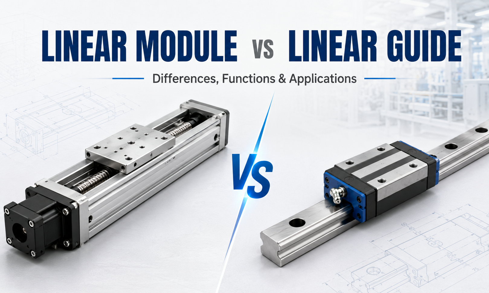
Alinear moduleand alinear guideare both essential components in industrial linear motion systems, but they perform fundamentally different functions. A linear guide mainly supports and guides a moving load along a straight path, while a linear module is a complete motion unit that combines a guide system, drive mechanism, carriage, structural base, and motor interface.
Because linear modules usually contain linear guides, the two terms are sometimes used interchangeably. This can create confusion during equipment design and component selection. A linear guide alone cannot normally move a load automatically. It requires an external drive mechanism such as a ball screw, timing belt, rack and pinion, pneumatic cylinder, hydraulic cylinder, or linear motor.
A linear module, by comparison, is designed to generate controlled linear movement after being connected to a motor andmotion controller. It provides guidance, transmission, support, and mounting functions within an integrated structure.
Understanding thelinear module vs linear guide differenceis important when designing packaging machinery, semiconductor equipment, CNC systems, electronic assembly lines, inspection equipment,Cartesian robots, material handling systems, and other industrial automation equipment.
This guide explains the differences between linear modules and linear guides in structure, function, drive method, positioning accuracy, load capacity, installation, maintenance, cost, and industrial applications.
What Is a Linear Guide?
Alinear guide, also known as a linear motion guide, linear guide rail, or linear rail system, is a mechanical component that supports a moving load and constrains it to travel along a straight path.
A typical linear guide system consists of a hardened guide rail and one or more guide blocks. Recirculating steel balls or rollers move between the rail and the guide block, reducing friction and allowing smooth linear movement.
The guide rail is mounted to a machine frame, base plate, aluminum profile, or other structural surface. The moving table, fixture, tooling, or machine component is attached to the guide blocks.
The primary purpose of a linear guide is not to generate motion. Its function is to guide movement, support loads, resist moment forces, and maintain the required motion direction.
Main Functions of a Linear Guide
- Guide a moving component along a straight path
- Support radial, reverse-radial, and lateral loads
- Resist pitch, yaw, and roll moments
- Reduce friction between moving components
- Improve movement smoothness
- Maintain parallelism and directional stability
- Provide rigidity for precision machine structures
Main Components of a Linear Guide
- Guide rail
- Guide block or carriage block
- Recirculating balls or rollers
- End caps and return passages
- Seals and scrapers
- Lubrication ports
- Mounting bolts and reference surfaces
What Is a Linear Module?
Alinear moduleis an integrated linear motion assembly designed to move a carriage accurately and repeatedly along a defined stroke. It combines the guiding structure and the drive mechanism into a complete unit.
Depending on the design, a linear module may use a ball screw, timing belt, rack and pinion, linear motor, lead screw, or another transmission mechanism. The guide system may consist of profile rails, embedded rails, shaft guides, roller guides, or integrated guide surfaces.
The drive mechanism converts motor rotation or electromagnetic force into linear movement. The guide system supports the payload and controls the direction of motion. The structural base maintains alignment between the drive and guide components.
Most industrial linear modules can be connected directly to a servo motor or stepper motor. Sensors, limit switches, protective covers, cable carriers, brakes, and lubrication systems may also be integrated.
Main Functions of a Linear Module
- Generate controlled linear motion
- Guide and support the moving payload
- Convert motor rotation into linear displacement
- Provide positioning and repeatability
- Transmit thrust
- Provide a standardized motor mounting interface
- Simplify installation and system integration
- Support single-axis and multi-axis automation
Main Components of a Linear Module
- Structural base or aluminum profile
- Linear guide rail and guide blocks
- Moving carriage
- Drive mechanism
- Drive-end and support-end assemblies
- Motor mounting plate
- Coupling or pulley system
- Protective cover or sealing strip
- Limit and home sensors
- Lubrication components
Linear Module vs Linear Guide: Quick Comparison
| Comparison Factor | Linear Module | Linear Guide |
|---|---|---|
| Primary Function | Generates and controls linear motion | Guides and supports linear motion |
| Drive Mechanism | Normally integrated | Not included |
| Guide System | Integrated into the module | The component itself is the guide system |
| Motor Interface | Usually provided | Not normally provided |
| Position Control | Can perform controlled positioning | Cannot position independently |
| Structure | Complete motion assembly | Individual mechanical component |
| Installation | Relatively standardized | Requires separate system design |
| Load Support | Depends on guides, base, carriage, and drive | Can provide very high load and moment capacity |
| Customization | Limited by module structure and available options | Highly flexible for custom machine design |
| Typical Use | Automated positioning and material transfer | Machine guidance and structural support |
The Fundamental Difference: Guidance vs Actuation
The most important difference is that a linear guide is aguidance component, while a linear module is alinear actuator assembly.
A linear guide controls the path of movement. It prevents the moving object from shifting sideways, rotating excessively, or leaving the intended straight-line direction. However, it does not normally provide the force required to move the load.
A linear module includes a transmission or driving system that generates movement. When the motor rotates, the module moves its carriage along the guide system according to commands from the controller.
A simple comparison can be made with a railway system. The linear guide acts like the track that defines and supports the travel path. The drive mechanism provides the force that moves the vehicle. A linear module combines the track, moving platform, and drive system into one functional unit.
Structural Differences
Linear Guide Structure
A linear guide is relatively simple. It normally contains a rail and guide blocks. It must be mounted onto a sufficiently flat and rigid machine surface.
The equipment designer must separately select and install the drive system, moving table, motor, support bearings, coupling, protective structure, sensors, and other required components.
A custom linear stage may use two parallel guide rails, four guide blocks, a machined steel or aluminum base, a ball screw, support bearings, a coupling, and a servo motor. In this system, the linear guides are only one part of the complete motion axis.
Linear Module Structure
A linear module integrates most of these components into a standardized assembly. The guide rails, carriage, transmission mechanism, bearing supports, and structural base are aligned during manufacturing and assembly.
This integrated design reduces the amount of mechanical engineering required by the machine builder. The customer usually only needs to mount the module, install the motor or select a motor-integrated version, connect sensors, and complete control system commissioning.
Drive System Differences
A linear guide does not determine how the system is driven. It can be combined with many different types of actuators.
Common Drive Systems Used with Linear Guides
- Ball screw
- Lead screw
- Timing belt
- Rack and pinion
- Linear motor
- Pneumatic cylinder
- Hydraulic cylinder
- Manual handwheel
- Cam or linkage mechanism
This flexibility makes linear guides suitable for highly customized equipment. Engineers can independently select the rail size, block configuration, base structure, transmission type, motor, and control system.
A linear module already contains a specific drive system. For example, a ball screw linear module uses a ball screw transmission, while a belt driven linear module uses a timing belt and pulley system.
The selected module type therefore determines many of the axis characteristics, including speed, stroke, thrust, rigidity, noise, maintenance requirements, and positioning capability.
Positioning Accuracy Comparison
Accuracy comparisons between linear modules and linear guides must be made carefully because they use different performance definitions.
A linear guide is normally evaluated according to rail straightness, running parallelism, height variation, width variation, preload, clearance, and manufacturing accuracy class.
A linear module is evaluated according to positioning accuracy, repeatability, backlash, lead accuracy, resolution, straightness of travel, parallelism, and lost motion.
Linear Guide Accuracy
The accuracy of a linear guide determines how smoothly and consistently the guide block moves relative to the rail. A high-accuracy guide can improve the straightness, parallelism, and rigidity of the machine axis.
However, a precision linear guide does not automatically make the complete axis accurate. The final positioning performance also depends on the drive mechanism, base machining, installation alignment, thermal expansion, motor control, feedback system, and load deformation.
Linear Module Accuracy
The accuracy of a linear module describes the performance of the complete motion assembly. Aball screw modulewith a preloaded nut and servo motor may achieve high repeatability and controlled positioning.
A belt driven module may provide high speed and long travel but usually has lower axial rigidity because of belt elasticity. A linear motor module may provide high dynamic performance without mechanical transmission backlash, but its final accuracy depends heavily on the encoder and control system.
Which One Is More Accurate?
It is not technically correct to say that either a linear guide or a linear module is always more accurate. A guide rail provides guidance accuracy, while a module provides complete-axis positioning performance.
A custom stage built with precision linear guides, a high-grade ball screw, a rigid base, and a linear encoder may achieve higher accuracy than a standard linear module. However, achieving this performance requires more engineering, machining, assembly, and calibration.
A standardized linear module may provide more predictable performance and easier integration for most automation applications.
Repeatability and Resolution
A linear guide alone has no independent repeatability or control resolution because it does not contain a drive or feedback system.
Repeatability refers to the ability of an actuator to return to the same commanded position repeatedly. Resolution refers to the smallest movement that the control and transmission system can command or detect.
These characteristics are determined by the complete axis, including the motor, encoder, drive mechanism, controller, mechanical rigidity, and load condition.
Alinear module manufacturermay specify repeatability for the complete product. A linear guide manufacturer normally specifies geometric and running accuracy rather than positioning repeatability.
Load Capacity Comparison
Linear guides can provide extremely high load capacity relative to their size. Depending on the design, they can support loads in multiple directions and resist pitch, yaw, and roll moments.
The load capacity of a linear guide depends on the rail size, number of guide blocks, ball or roller design, preload, mounting arrangement, load direction, lubrication, and service life requirement.
A linear module also uses guide components to support its payload, but its rated load may be limited by additional factors.
Factors Limiting Linear Module Load
- Guide rail and guide block capacity
- Carriage size and rigidity
- Aluminum profile or base rigidity
- Ball screw or belt transmission capacity
- Bearing support capacity
- Motor torque
- Acceleration and deceleration
- Mounting orientation
- Load center-of-gravity offset
- Required service life
A large linear guide mounted on a heavy steel frame may support much higher loads than a compact aluminum linear module. However, the guide system still needs an appropriate drive mechanism to move the load.
Moment Load Capacity
Moment load capacity is especially important when the payload is mounted away from the guide blocks or carriage surface.
The three main moment directions are pitch, yaw, and roll. Excessive moment loading can cause uneven guide block loading, reduced accuracy, increased friction, vibration, and premature wear.
A custom system using two guide rails and four widely spaced blocks can provide excellent moment resistance. Designers can adjust rail spacing, block spacing, and base dimensions according to the application.
A linear module has a fixed carriage width and guide arrangement. Its moment capacity is therefore limited by the module structure. Larger modules, longer carriages, or parallel dual-module configurations may be required for high moment loads.
Rigidity Comparison
Linear guide systems can achieve very high structural rigidity when mounted on a precision-machined steel or cast-iron base. Roller-type linear guides are often used in machine tools and heavy-duty equipment requiring high stiffness.
Many standardized linear modules use aluminum profiles to reduce weight, manufacturing cost, and installation complexity. Aluminum modules provide sufficient rigidity for most automation tasks, but they may not match the stiffness of a custom steel stage.
The actual rigidity of a linear module also depends on the drive system. Ball screw modules normally offer higher axial rigidity than belt driven modules. Linear motor modules avoid mechanical transmission elasticity but require a rigid structure and suitable control tuning.
Speed and Acceleration Comparison
A linear guide does not directly determine axis speed. The maximum practical speed depends on the guide type, lubrication, preload, block design, drive system, stroke, and machine structure.
Modern linear guides can support high-speed movement when correctly selected and lubricated. However, the actual axis speed is usually determined by the actuator.
A belt driven module is commonly selected for high-speed, long-stroke movement. A ball screw module provides strong thrust and precise positioning but may be limited by screw critical speed. A linear motor module can provide very high speed and acceleration because it has no rotating transmission component.
When linear guides are used in a custom machine, the designer can choose any suitable drive type. A linear module offers less design freedom but provides a tested combination of guide and drive components.
Stroke Length Comparison
Linear guides are available in many lengths and can sometimes be joined to create extremely long travel systems. Their practical length is determined by rail manufacturing, mounting accuracy, joint alignment, machine base quality, and transportation limits.
The stroke of a linear module is limited by the module profile, transmission system, support structure, and manufacturer specifications.
Ball screw modules are usually more suitable for short and medium strokes. Belt driven and rack driven modules are more suitable for long strokes. Linear motor modules can also support long travel but usually involve higher cost and more demanding feedback requirements.
For very long industrial axes, a custom guide rail system combined with rack and pinion drive may provide greater flexibility than a standard module.
Installation Differences
Installing a Linear Guide
Linear guide installation requires a flat, rigid, and accurately machined mounting surface. When two parallel rails are used, their height, parallelism, and reference alignment must be controlled carefully.
Incorrect guide installation can cause binding, uneven preload, abnormal noise, increased motor load, reduced accuracy, and shortened service life.
After installing the guides, the machine builder must install and align the drive system. The relationship between the screw, belt, rack, motor, bearings, carriage, and rails must be controlled.
Installing a Linear Module
A linear module is generally easier to install because the internal guide and drive components have already been assembled and aligned.
The user normally mounts the module to the machine frame through specified mounting holes or clamping surfaces. The mounting base must still be sufficiently flat and rigid, but the internal component alignment does not need to be recreated.
This can shorten equipment assembly time and reduce the risk of installation errors.
Space and Machine Layout
A linear module provides a compact and standardized structure. The motor interface, carriage, guide system, and transmission are arranged within a defined envelope, making it easier to design machine layouts.
A custom system using separate linear guides provides greater freedom. The designer can position the motor, screw, belt, rails, bearings, and carriage according to available space.
This flexibility is useful when the machine has unusual geometry, limited installation space, special load paths, or strict rigidity requirements.
However, custom layouts require more detailed engineering and may increase the risk of component interference or alignment problems.
Maintenance Differences
Linear Guide Maintenance
Linear guides require regular lubrication and protection from contamination. Dust, metal particles, coolant, and abrasive debris can enter the rolling surfaces and cause wear.
- Check lubrication condition
- Clean exposed rail surfaces
- Inspect seals and scrapers
- Check guide block noise and vibration
- Inspect mounting bolts
- Monitor movement resistance
- Check rail corrosion or surface damage
Linear Module Maintenance
Linear module maintenance includes guide maintenance as well as inspection of the drive system.
- Lubricate guide rails and ball screws when required
- Inspect timing belt tension and wear
- Check ball screw backlash
- Inspect support bearings and couplings
- Check pulleys and belt teeth
- Inspect protective covers and sealing strips
- Check sensors and cable routing
- Monitor positioning accuracy and abnormal noise
A linear module has more components than a guide rail, but its integrated structure may make maintenance planning more standardized.
Cost Comparison
The component price of a linear guide is normally lower than the price of a complete linear module because the guide is only one part of the motion system.
However, comparing only component prices is misleading. A linear guide-based axis also requires a structural base, drive mechanism, bearings, motor mount, coupling, carriage plate, sensors, covers, machining, assembly, and alignment.
A linear module may have a higher initial purchase price but can reduce engineering time, machining requirements, assembly labor, and commissioning risk.
Costs of a Custom Linear Guide System
- Guide rails and blocks
- Machined base or frame
- Drive mechanism
- Support bearings
- Motor and motor mount
- Coupling or pulley components
- Moving table
- Protective cover
- Sensors and brackets
- Engineering and design time
- Assembly and alignment labor
- Testing and calibration
Costs of a Linear Module System
- Module purchase price
- Motor and drive
- Mounting brackets
- Sensors and cables
- Installation and commissioning
- Periodic maintenance
For standard automation machines, a linear module often provides a lower total integration cost. For high-volume equipment or highly specialized machinery, a custom guide-based stage may provide better performance or lower long-term manufacturing cost.
Design Flexibility Comparison
Linear guides provide maximum design flexibility. Engineers can independently define rail spacing, block spacing, carriage dimensions, material, drive type, motor position, and protective structure.
This makes them suitable for machine tools, special-purpose machinery, heavy-duty platforms, vacuum equipment, cleanroom machines, and systems with unusual dimensional constraints.
Linear modules provide standardized configuration options. Stroke, module width, drive type, motor orientation, sensor location, and accessories can often be selected, but the internal architecture is mostly fixed.
The standardized structure reduces design freedom but improves selection efficiency and shortens development time.
Typical Linear Guide Applications
- CNC machine tool axes
- Machining centers
- Grinding machines
- Large custom motion platforms
- Precision measuring machines
- Injection molding equipment
- Industrial robot guide axes
- Semiconductor process equipment
- Heavy-load transfer platforms
- Manual sliding tables
- Machine doors and protective systems
- Custom automation mechanisms
In these applications, the linear guide is normally combined with a separate actuator or used to guide a manually or mechanically driven component.
Typical Linear Module Applications
- Pick-and-place systems
- Electronic assembly
- Automatic dispensing
- Vision inspection
- Packaging machinery
- Labeling and printing equipment
- Automatic loading and unloading
- Cartesian robots
- Gantry automation systems
- Laboratory automation
- Battery manufacturing equipment
- Semiconductor handling equipment
- Medical device automation
- Sorting and material transfer
Linear modules are especially useful when the equipment requires a compact, ready-to-integrate motion axis with predictable performance.
When Should You Choose a Linear Module?
- The machine requires automatic point-to-point positioning
- The development schedule is limited
- A standardized motion axis is acceptable
- The application requires easy motor integration
- Installation and commissioning time must be reduced
- The machine uses multiple similar axes
- The application requires a compact structure
- Repeatable performance is more important than complete design freedom
- The engineering team wants to reduce custom machining
- The axis will be integrated into an XY, XZ, XYZ, or gantry system
When Should You Choose Separate Linear Guides?
- The machine requires a highly customized structure
- The payload or moment load exceeds standard module capacity
- The equipment needs very high structural rigidity
- Rail spacing and block spacing must be optimized
- The application uses a special drive mechanism
- The installation space has unusual dimensional limits
- The system requires a custom steel or cast-iron base
- The machine will be produced in high volume
- The design requires special environmental protection
- The axis performance exceeds available standard modules
Can Linear Guides and Linear Modules Be Used Together?
Yes. A linear module already contains a guide system, but additional external linear guides may be used in some applications.
For example, a wide moving platform may be driven by one central linear module while external guide rails support both sides of the platform. This arrangement can increase moment capacity and prevent the platform from rotating.
However, all guide systems must be installed with sufficient parallelism. If the module and external guides are misaligned, they can create internal stress, binding, increased friction, and premature wear.
In large gantry systems, two parallel linear modules may also be synchronized electronically or mechanically to support a wide crossbeam.
Common Selection Mistakes
Using a Linear Guide Without a Drive Plan
A guide rail cannot automatically move a payload. The complete system must include an actuator, motor, transmission, and control method.
Assuming a Linear Module Can Carry Any Load
The module must be selected according to payload, acceleration, mounting direction, moment load, speed, and service life.
Comparing Guide Accuracy Directly with Module Repeatability
These parameters describe different performance characteristics. Guide running accuracy is not the same as complete-axis positioning accuracy.
Ignoring Mounting Surface Quality
Both linear guides and linear modules require a sufficiently rigid and flat mounting base. Poor installation surfaces can deform the rail or module and reduce performance.
Ignoring Moment Loads
A payload may be within the stated weight limit but still overload the guide blocks because of a large center-of-gravity offset.
Selecting Only by Component Price
A custom guide-based axis may appear less expensive until machining, engineering, assembly, alignment, testing, and maintenance costs are included.
Selection Examples
Compact Pick-and-Place Machine
A machine must move small components between two positions at high speed. The stroke and payload are moderate, and rapid equipment development is important. A belt driven or ball screw linear module is usually the most efficient solution.
Heavy-Duty Machine Tool Axis
A machine axis must support heavy cutting loads and resist large moments. A custom system using roller linear guides, a rigid cast-iron base, and a heavy-duty ball screw may be more suitable than a standard aluminum module.
Precision Inspection Equipment
An inspection system requires accurate positioning and compact integration. A precision ball screw or linear motor module with encoder feedback can simplify system design.
Wide Transfer Platform
A large platform must support a wide fixture. A central linear module may provide the drive while two external guide rail systems support the platform and resist moment loads.
Long-Stroke Material Handling Axis
A transfer axis must move products over several meters. A belt driven linear module or a custom rack-and-pinion system using separate guide rails may be selected according to payload, speed, rigidity, and budget.
Important Parameters to Confirm Before Selection
- Function:Determine whether the component only needs to guide movement or must also generate movement.
- Stroke:Confirm the required effective travel distance.
- Payload:Include tooling, workpieces, cables, sensors, and accessories.
- Mounting orientation:Specify horizontal, vertical, side-mounted, inverted, or inclined installation.
- Speed:Define maximum and normal operating speed.
- Acceleration:Confirm acceleration and deceleration requirements.
- Accuracy:Distinguish between guide accuracy, positioning accuracy, repeatability, and resolution.
- Moment load:Calculate pitch, yaw, and roll moments.
- External force:Include cutting, pressing, friction, and process resistance.
- Duty cycle:Confirm operating time, travel frequency, and total distance.
- Environment:Identify dust, oil, chips, cleanroom, vacuum, temperature, humidity, and chemical exposure.
- Maintenance:Define lubrication and inspection requirements.
- Integration:Consider motor, controller, sensors, cables, and safety devices.
- Budget:Compare total system cost rather than individual component prices.
Frequently Asked Questions
Is a linear module the same as a linear guide?
No. A linear guide supports and guides movement, while a linear module is a complete actuator assembly containing a guide system and a drive mechanism.
Does a linear module contain linear guides?
Most industrial linear modules contain one or more linear guide rails or another type of guiding structure. The guide system supports the carriage while the transmission mechanism generates movement.
Can a linear guide move without a motor?
A guide block can be moved manually or by an external force, but the linear guide itself does not generate motion. Automatic movement requires a separate actuator.
Which has higher load capacity?
A custom linear guide system can often support higher loads and moments because engineers can use larger rails, more blocks, wider spacing, and a stronger base. A standard linear module provides load capacity within a compact integrated structure.
Which is more accurate?
They cannot be compared using a single accuracy value. A linear guide has geometric and running accuracy, while a linear module has complete-axis positioning and repeatability specifications.
Which is easier to install?
A linear module is generally easier to install because the drive and guide systems are already integrated and aligned. Separate linear guides require additional mechanical design and installation work.
Which option costs less?
A linear guide has a lower individual component cost, but a complete guide-based axis may require substantial machining, assembly, and engineering. A linear module may provide a lower total integration cost for standard automation applications.
Can a linear module replace a machine tool guide system?
Not always. Machine tools often require high rigidity, heavy load capacity, special accuracy, thermal stability, and custom structural dimensions that may exceed the capabilities of standard linear modules.
Conclusion
The key difference in thelinear module vs linear guidecomparison is their function. A linear guide is a mechanical guidance component that supports a load and controls its movement direction. A linear module is a completelinear actuatorthat integrates guidance, transmission, support, and motor connection into one assembly.
Choose a linear module when the application requires a compact, standardized, and easy-to-integrate motion axis. It can reduce design work, machining, installation time, and commissioning complexity.
Choose separate linear guides when the application requires greater structural freedom, higher load capacity, wider rail spacing, special drive systems, or machine-tool-level rigidity.
The correct solution should be selected according to the complete application requirements, including payload, stroke, speed, acceleration, accuracy, moment load, mounting direction, environmental conditions, maintenance, integration cost, and expected service life.
By distinguishing between the guiding function of a linear guide and the actuating function of a linear module, engineers can avoid incorrect component selection and design more reliable, efficient, and economical linear motion systems.
