 English

Atiming belt linear moduleis a mechanical linear motion system that converts the rotary motion of a motor into controlled linear movement through a toothed timing belt and pulley mechanism. It integrates the belt transmission, linear guide, carriage, aluminum base, end blocks, motor mount, tensioning mechanism, sensors and protective components into a complete linear axis.
Compared with aball screw linear module, a belt driven linear module does not rely on a long rotating screw to transmit motion. Instead, a lightweight timing belt circulates continuously between a drive pulley and an idler pulley, moving the carriage along the guide rail. This design makes the module particularly suitable for applications requiring high speed, high acceleration and long travel.
Because of its simple transmission structure, low moving mass and flexible stroke configuration, thetiming belt linear moduleis widely used in packaging machinery, material handling systems, electronic assembly equipment, pick-and-place machines, visual inspection systems, automated production lines and Cartesian robots.
This guide explains the definition, working principle, structure, main components, performance characteristics, advantages, limitations, typical applications and basic selection considerations of a timing belt linear module.
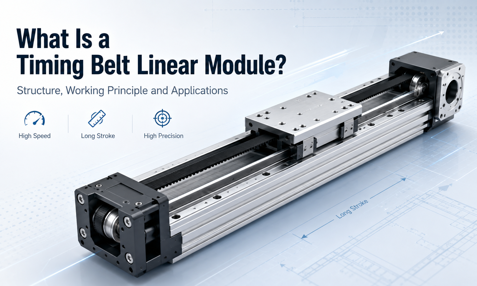
What Is a Timing Belt Linear Module?
A timing belt linear module, also known as abelt driven linear module, timing belt actuator, belt driven linear stage or linear belt actuator, is an integrated motion unit designed to move a load along a straight path.
The module normally consists of a rigid aluminum profile, one or more linear guide rails, a moving carriage, a toothed timing belt, two timing pulleys, bearings, end blocks, a motor connection interface and a belt tensioning mechanism.
When the motor rotates the drive pulley, the pulley pulls the timing belt around the module. The carriage is mechanically connected to the belt, so the linear section of the moving belt carries the carriage forward or backward along the guide rail.
The timing belt has molded teeth that engage with matching teeth on the timing pulleys. This positive engagement reduces slippage and allows the carriage position to be controlled more accurately than with an ordinary friction belt.
The linear guide system supports the external load and constrains the carriage to move along a defined path. The timing belt primarily transmits driving force, while the guide rail and guide blocks carry radial loads, lateral loads and overturning moments.
Basic Operating Principle of a Timing Belt Linear Module
The working principle of a timing belt linear module can be understood as a rotary-to-linear motion conversion process.
- The motor generates rotary motion and torque.
- The motor shaft drives the timing pulley directly or through a gearbox or coupling.
- The drive pulley moves the toothed timing belt around the module.
- The belt transmits force to the connected carriage.
- The carriage moves along the linear guide rail.
- The idler pulley redirects the belt and maintains a continuous closed-loop transmission path.
- The tensioning mechanism maintains the correct belt preload.
- Sensors and themotion controllerdefine the home position, travel limits, speed and target position.
The direction of linear movement depends on the rotational direction of the motor. Reversing the motor reverses the direction of the belt and therefore the direction of the carriage.
Relationship Between Pulley Rotation and Linear Travel
The linear travel produced by one complete revolution of the drive pulley depends on the belt pitch and the number of teeth on the pulley.
Linear travel per pulley revolution = belt pitch × number of pulley teeth
For example, if a timing belt has a pitch of 5 mm and the drive pulley has 20 teeth, one pulley revolution produces a theoretical linear travel of 100 mm.
This relationship makes it possible to calculate the motor speed required for a target linear velocity. However, actual positioning performance is also affected by belt elasticity, pulley machining accuracy, belt tension, load variation, guide accuracy and control system settings.
Structure Overview of a Timing Belt Linear Module
A timing belt linear module is designed as an integrated mechanical assembly. Although the exact construction varies between manufacturers and product series, most modules include the following structural sections.
Aluminum Base Profile
The aluminum profile forms the main body of the module. It supports the guide rail, end blocks, pulleys, carriage and external mounting components.
A well-designed base profile must provide sufficient bending rigidity and torsional rigidity. For long-stroke modules, the profile may require intermediate support points to prevent excessive deflection.
Linear Guide System
The linear guide rail is mounted along the length of the base. One or more guide blocks move along the rail and support the carriage.
The guide system determines the module’s load capacity, straightness, rigidity and resistance to overturning moments. It also prevents the timing belt from carrying loads that should be supported mechanically by the guide rail.
Timing Belt Transmission
The transmission system normally includes a toothed timing belt, a drive pulley and an idler pulley. The belt runs around both pulleys to form a closed loop.
The drive pulley receives torque from the motor. The idler pulley supports the opposite end of the belt path and may be connected to the tensioning mechanism.
Moving Carriage
The carriage is the moving platform used to mount a workpiece, gripper, dispensing head, camera, sensor, welding tool or another automation component.
The carriage is connected to the guide blocks and clamped to the timing belt. Its dimensions and bearing arrangement influence load capacity and moment resistance.
End Blocks
The end blocks are installed at both ends of the aluminum profile. They support the pulleys, bearings and belt path while protecting the internal transmission components.
Depending on the module design, one end block may also serve as the motor mounting side and the other as the belt tensioning side.
Motor Mounting Interface
The motor mount connects a servo motor, stepper motor or geared motor to the drive pulley. The motor may be installed in a direct, side-mounted, bottom-mounted or folded-back configuration.
The selected arrangement affects the overall module length, installation space and accessibility for maintenance.
Belt Tensioning Mechanism
The tensioning mechanism adjusts the distance or relative position of the pulley assembly to establish the correct belt tension.
Insufficient tension may cause vibration, tooth jumping, poor repeatability or delayed response. Excessive tension increases bearing loads, belt stress and power consumption.
Sensors and Protective Components
Timing beltlinear modulesmay include home sensors, limit sensors, sensor brackets, cable routing components, belt covers, dust strips, protective plates and mechanical end stops.
These components improve operational safety, protect the transmission system and help the controller identify the module position.
Main Components and Their Functions
| Component | Main Function |
|---|---|
| Aluminum base profile | Supports the complete module and provides structural rigidity. |
| Linear guide rail | Defines the movement path and carries external loads. |
| Guide block | Moves along the guide rail and supports the carriage. |
| Timing belt | Transmits motor force to the moving carriage. |
| Drive pulley | Converts motor rotation into belt movement. |
| Idler pulley | Redirects the belt and completes the closed-loop belt path. |
| Carriage | Provides the mounting surface for the moving load or tool. |
| Bearings | Support pulley rotation and reduce friction. |
| End blocks | Support the pulleys and protect both ends of the module. |
| Motor mount | Connects the motor to the module transmission system. |
| Tensioning mechanism | Adjusts and maintains the required timing belt tension. |
| Home and limit sensors | Provide position references and travel limit signals. |
| Protective cover | Reduces the entry of dust and protects moving parts. |
| Fasteners and locating elements | Maintain alignment and secure the mechanical assembly. |
Performance Characteristics of Timing Belt Linear Modules
High Linear Speed
One of the most important characteristics of a timing belt linear module is its ability to achieve high linear speed. Because the belt has relatively low mass and does not require a long screw to rotate at high speed, belt driven systems are well suited to rapid transfer operations.
The actual maximum speed depends on the belt type, pulley diameter, motor speed, stroke length, payload, guide system and structural rigidity.
High Acceleration
The lightweight transmission system allows the carriage to accelerate and decelerate quickly. This characteristic can shorten cycle time in packaging, sorting, pick-and-place and material transfer applications.
High acceleration must still be evaluated carefully because acceleration force increases with moving mass. Rapid acceleration also increases belt tension variation, motor torque demand and structural vibration.
Long Travel Capability
A timing belt actuator can be designed for relatively long travel because its operating speed is not directly limited by the critical rotational speed of a long ball screw.
This makestiming belt modulessuitable for long machine axes, conveyor-like positioning systems,gantry robotsand warehouse automation equipment.
For very long strokes, profile deflection, belt elongation, installation alignment and support spacing become increasingly important.
Moderate Positioning Accuracy
Timing belt modules provide reliable positioning for many industrial automation tasks, but their positioning accuracy is generally lower than that of precision ball screw or linear motor systems.
Belt elasticity, load variation, temperature, belt tension and acceleration can influence the actual position of the carriage. A closed-loop servo system can improve control performance, but it cannot completely eliminate mechanical belt deformation.
Good Repeatability
When the belt is correctly tensioned and the load remains stable, a timing belt linear module can provide good repeatability for repeated point-to-point motion.
Repeatability is often more important than absolute positioning accuracy in applications such as loading, unloading, transferring, sorting and dispensing at fixed workstations.
Low Transmission Noise
A properly installed timing belt transmission generally operates with less noise than many metal gear or screw transmission systems. The belt also absorbs a limited amount of shock and vibration.
Abnormal noise may indicate incorrect belt tension, pulley misalignment, damaged belt teeth, bearing wear or contamination in the guide system.
Low Maintenance Requirements
The timing belt itself does not normally require lubrication. Maintenance mainly involves checking belt tension, belt wear, pulley alignment, guide lubrication, fastener condition and sensor operation.
The linear guide rail and guide blocks still require appropriate lubrication according to the operating environment and duty cycle.
Common Timing Belt Linear Module Configurations
Open-Type Module
An open-type module exposes more of the guide and belt system. It is easy to inspect and maintain and is often suitable for clean indoor automation equipment.
However, it provides less protection against dust, debris and accidental contact.
Semi-Enclosed Module
A semi-enclosed timing belt module uses covers or dust strips to protect part of the internal mechanism while maintaining a relatively compact structure.
This configuration provides a balance between accessibility, cost and environmental protection.
Fully Enclosed Module
A fully enclosed timing belt linear module uses a protective housing or cover system to reduce the entry of dust and foreign particles.
It is more suitable for applications where the motion system is exposed to production debris or where improved operator protection is required. However, enclosure alone does not automatically make a module waterproof or suitable for severe contamination.
Single-Guide and Dual-Guide Designs
A single-guide design is compact and economical for moderate loads. A dual-guide or wide-guide arrangement provides greater resistance to lateral loads and overturning moments.
The correct design should be selected according to payload position, carriage size, acceleration and applied moments rather than load weight alone.
Different Motor Mounting Directions
The motor may be installed in line with the module, on the side, underneath the module or in a folded-back arrangement using an additional belt transmission.
Motor orientation is normally selected according to available machine space, cable routing, maintenance access and overall axis length.
Advantages of Timing Belt Linear Modules
- High speed:Suitable for fast point-to-point movement and rapid material transfer.
- High acceleration:Low transmission mass supports short motion cycles.
- Long stroke:Suitable for travel distances that may be difficult for high-speed ball screw systems.
- Simple mechanical structure:Fewer complex transmission components simplify integration and maintenance.
- Low operating noise:The belt transmission normally produces smooth and relatively quiet movement.
- Flexible motor arrangement:Multiple motor mounting directions can be configured.
- Cost-effective automation:Provides a practical balance between speed, stroke, accuracy and cost.
- Easy multi-axis integration:Can be combined into XY, XZ, XYZ and gantry motion systems.
Limitations of Timing Belt Linear Modules
Although timing belt linear modules offer many advantages, they are not suitable for every positioning task.
- Belt elasticity limits absolute positioning accuracy under changing loads.
- Very high thrust applications may require a larger belt, multiple belts or another transmission method.
- Incorrect belt tension can reduce repeatability and service life.
- Long vertical axes require careful evaluation of gravity, holding brakes and fall protection.
- Temperature changes can influence belt length and system accuracy.
- High moment loads may require a wider carriage or additional guide rails.
- Sharp debris, oil, chemicals and heat may damage unsuitable belt materials.
- The belt is a wear component and requires periodic inspection and eventual replacement.
Timing Belt Linear Module vs. Ball Screw Linear Module
| Comparison Item | Timing Belt Linear Module | Ball Screw Linear Module |
|---|---|---|
| Typical strength | High speed and long stroke | High precision and high thrust |
| Transmission element | Toothed timing belt | Ball screw and ball nut |
| Positioning accuracy | Moderate | Generally higher |
| Linear speed | Generally higher | Limited by screw speed and stroke |
| Long-stroke capability | Very suitable | Requires evaluation of critical speed and screw support |
| Thrust capacity | Suitable for light to medium thrust in many configurations | Suitable for medium to high thrust |
| Noise | Relatively low | May increase at high rotational speed |
| Maintenance | Belt inspection and guide lubrication | Screw and guide lubrication |
| Typical applications | Transfer, sorting, packaging and long-stroke motion | Machining, pressing, precision assembly and accurate positioning |
The correct choice depends on the application. A timing belt system is often preferred when speed and stroke are the main priorities. A ball screw system is usually more suitable when positioning accuracy, rigidity and axial thrust are more important.
Typical Applications of Timing Belt Linear Modules
Pick-and-Place Systems
Timing belt modules provide fast movement between loading, processing and unloading positions. They are commonly used as horizontal axes in pick-and-place machines.
Packaging Machinery
Packaging lines require rapid and repetitive movement for product transfer, carton handling, labeling, sealing and palletizing. Belt driven linear modules can help reduce cycle time in these operations.
Electronic Assembly
In electronics manufacturing, timing belt actuators can move fixtures, trays, cameras, dispensing tools and handling devices between multiple stations.
Visual Inspection Systems
A timing belt linear stage can move a camera or inspection object across a long measurement area. The module can be combined with encoders and servo control when more consistent motion is required.
Material Handling and Sorting
High speed and long travel make timing belt modules suitable for sorting equipment, warehouse systems, conveyor transfer mechanisms and automated loading equipment.
Dispensing and Gluing Equipment
Timing belt modules can be used in automated dispensing systems when the process requires fast movement over a relatively large work area and does not require extremely high machining-level accuracy.
Laser Processing Equipment
Some laser marking, cutting and engraving systems use belt driven axes for rapid positioning. The required accuracy and speed must be evaluated according to the specific laser process.
Cartesian and Gantry Robots
Multiple timing belt linear modules can be combined into XY, XZ, XYZ or gantry structures. Long horizontal belt axes are especially useful for transferring products across multiple workstations.
Automated Production Lines
Timing belt modules can connect separate machines, move components between processes and support repetitive handling tasks throughout an automated line.
How to Select a Timing Belt Linear Module
Determine the Required Stroke
The required stroke is the actual movement distance of the carriage. Additional space may be needed for acceleration, deceleration, sensor activation and mechanical safety margins.
The total module length is always greater than the effective stroke because the end blocks, pulley assemblies and carriage occupy part of the overall structure.
Calculate the Payload
Payload evaluation should include the workpiece, tooling, fixture, cables and all other moving components. The selected module must support both the static mass and the dynamic forces generated during acceleration and deceleration.
Evaluate Moment Loads
A load mounted away from the center of the carriage produces an overturning moment. Moment loads can be more critical than the payload weight itself.
Evaluate the load in all relevant directions and consider a longer carriage, wider guide spacing or dual-guide design when necessary.
Define Speed and Acceleration
Maximum speed alone is not enough to select a module. The motion profile, acceleration time, travel distance, cycle frequency and settling requirements must also be considered.
Short strokes may not provide enough distance for the module to reach its theoretical maximum speed.
Specify Accuracy and Repeatability
Positioning accuracy and repeatability are different specifications. Positioning accuracy describes how closely the carriage reaches the commanded absolute position. Repeatability describes how consistently it returns to the same position.
Applications with changing loads or strict absolute positioning requirements should account for belt elasticity and may require external position feedback.
Consider Installation Direction
Horizontal, vertical, wall-mounted and inverted installations create different load conditions. Vertical axes require additional consideration of gravity, motor holding torque, brake selection and safety protection.
Check the Operating Environment
Dust, moisture, oil mist, chemicals, temperature, cleanroom requirements and production debris can affect belt material, lubrication method, sealing design and service life.
Select the Motor and Drive System
The motor must provide sufficient speed, continuous torque and peak torque for the complete motion cycle. Motor inertia, pulley size, gearbox ratio, payload and acceleration should be evaluated together.
Servo motors are commonly used when high speed, dynamic response and closed-loop control are required. Stepper motors may be suitable for simpler, lower-cost positioning tasks with moderate performance requirements.
Installation Considerations
- Install the module on a flat and sufficiently rigid mounting surface.
- Follow the recommended fastening sequence to avoid twisting the profile.
- Use intermediate supports for long modules when required.
- Align parallel axes carefully in gantry or dual-axis systems.
- Avoid forcing external components into alignment through the carriage.
- Set sensors and mechanical limits before high-speed commissioning.
- Route cables so they do not pull on the carriage or interfere with movement.
- Confirm belt tension and pulley alignment before operation.
- Begin commissioning at low speed and gradually increase the motion parameters.
Maintenance Requirements
Regular inspection helps maintain reliable movement and reduces unexpected downtime.
- Inspect the belt for cracks, damaged teeth, edge wear and contamination.
- Check belt tension according to the manufacturer’s recommended method.
- Inspect pulley alignment and fastening condition.
- Lubricate the linear guide at the specified interval.
- Remove dust and debris from exposed moving areas.
- Check the carriage, motor mount and structural fasteners.
- Test home sensors, limit sensors and emergency stop functions.
- Investigate abnormal noise, vibration or positioning changes promptly.
The timing belt should not normally be lubricated unless a specific belt manufacturer explicitly requires it. Oil or grease applied to an unsuitable belt may attract contaminants or damage the belt material.
Frequently Asked Questions
Is a Timing Belt Linear Module Accurate?
A timing belt linear module provides sufficient accuracy and repeatability for many transfer, handling and packaging applications. However, its absolute positioning accuracy is generally lower than that of a precision ball screw or linear motor module because the belt can stretch under load.
Can a Timing Belt Linear Module Be Used for Long Strokes?
Yes. Long-stroke motion is one of the main advantages of a belt driven linear module. The profile support, belt elongation, installation alignment and required positioning accuracy must still be evaluated as the stroke increases.
Can a Timing Belt Module Be Installed Vertically?
Yes, but vertical installation requires careful calculation of payload, gravity, motor torque, brake capacity and safety measures. A holding brake or mechanical fall-prevention device may be required.
Does a Timing Belt Linear Module Require Lubrication?
The timing belt normally does not require lubrication, but the linear guide rail and guide blocks usually do. The correct lubricant and maintenance interval depend on the module design and operating environment.
What Causes Poor Repeatability in a Belt Driven Linear Module?
Common causes include insufficient belt tension, excessive belt tension, worn belt teeth, loose fasteners, pulley misalignment, unstable payload, guide wear, motor tuning problems and incorrect sensor settings.
How Long Does a Timing Belt Last?
Belt service life depends on operating speed, acceleration, load, tension, pulley diameter, environment, cycle frequency and maintenance. Regular inspection is more reliable than replacing every belt according to one universal time interval.
Should I Choose a Servo Motor or a Stepper Motor?
A servo motor is generally preferred for high-speed operation, rapid acceleration, closed-loop control and demanding duty cycles. A stepper motor may be suitable for lower-cost systems with moderate speed, load and positioning requirements.
Conclusion
Atiming belt linear moduleis an integrated linear motion system that uses a toothed timing belt and pulley mechanism to convert motor rotation into straight-line movement. Its main strengths are high speed, high acceleration, long travel, relatively low noise and straightforward mechanical construction.
The module combines a timing belt transmission with a linear guide, carriage, aluminum base, end blocks, motor interface, tensioning mechanism and sensors. The belt transmits driving force, while the guide system supports the load and maintains accurate linear movement.
Timing belt modules are particularly suitable for packaging, material handling, sorting, electronic assembly, visual inspection, pick-and-place operations, long-stroke transfer systems and Cartesian robots.
Successful selection requires more than checking payload and stroke. Speed, acceleration, repeatability, load moments, mounting direction, environmental conditions, motor torque, structural support and belt tension must all be evaluated as part of the complete motion system.
When high speed and long travel are more important than extremely high positioning accuracy, a belt driven linear module provides an efficient and cost-effective solution for modern industrial automation.
