 English

Accuracy is one of the most important performance indicators when selecting or designing a linear motion system. In semiconductor equipment, vision inspection machines, electronics assembly lines, precision dispensing systems, CNC machinery, and laboratory automation, even a small positioning error can affect product quality, process stability, and equipment reliability.
However,linear module accuracy calculationis not simply a matter of checking one value in a product catalog. The final motion accuracy of alinear moduleis influenced by positioning accuracy, repeatability, command resolution, ball screw lead error, backlash, guide rail precision, mounting conditions, servo control performance, temperature variation, and structural deformation.
A module may have extremely fine theoretical resolution but still produce poor actual positioning results. Similarly, a system can have excellent repeatability while maintaining a consistent offset from the commanded position. Engineers must therefore distinguish between resolution, positioning accuracy, repeatability, and total system error before evaluating a precision linear motion system.
This guide explains how to calculate linear module accuracy, identify the main sources of positioning error, evaluate repeatability, estimate total system precision, and improve accuracy through mechanical design, calibration, feedback control, and proper installation.
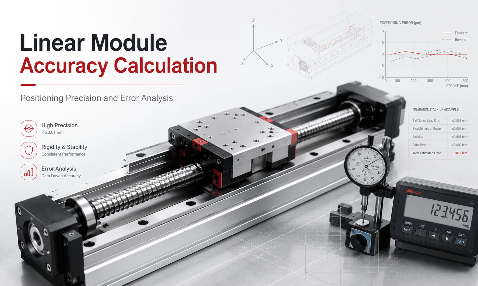
What Is Linear Module Accuracy?
Linear module accuracy describes how closely the actual position of the carriage matches the commanded or target position. It represents the difference between where the control system instructs the module to move and where the carriage actually stops.
The basic positioning error at a measured point can be expressed as:
Positioning error = Actual position − Commanded position
If a controller commands the carriage to move to 300.000 mm, but the measured position is 300.018 mm, the positioning error is:
300.018 mm − 300.000 mm = +0.018 mm
The positive value indicates that the carriage has moved 0.018 mm beyond the commanded position. If the measured position were 299.985 mm, the error would be −0.015 mm.
During a complete accuracy test, measurements are normally taken at multiple positions throughout the module stroke. The results are then used to determine maximum deviation, bidirectional error, repeatability, backlash, and compensation requirements.
Accuracy, Repeatability and Resolution Are Not the Same
One of the most common mistakes in linear motion system design is treating positioning accuracy, repeatability, and resolution as interchangeable specifications. These values describe different aspects of motion performance.
| Parameter | Definition | Main Influencing Factors |
|---|---|---|
| Positioning accuracy | How close the actual position is to the commanded position | Lead error, calibration, thermal expansion, feedback accuracy and mechanical alignment |
| Repeatability | How consistently the module returns to the same position under identical conditions | Backlash, friction, servo tuning, preload, vibration and load variation |
| Resolution | The smallest movement increment that the control system can theoretically command or detect | Encoder counts, screw lead, motor steps, microstepping and transmission ratio |
| Backlash | Lost motion when the direction of travel is reversed | Screw and nut clearance, coupling clearance, belt tension and transmission wear |
| Precision | A general description of the consistency and quality of motion performance | Combined mechanical, control, installation and environmental conditions |
A system with good repeatability can repeatedly stop at almost the same location but still have poor absolute positioning accuracy. For example, a carriage may repeatedly stop at 100.012 mm when commanded to move to 100.000 mm. The repeated results may be tightly grouped, but the system has a consistent positive offset of approximately 0.012 mm.
This type of systematic error can often be corrected through calibration or electronic error compensation. Random variation, inconsistent backlash, structural vibration, or changing friction is more difficult to compensate because the error does not remain constant.
How to Calculate Linear Module Positioning Error
For each measurement point, positioning error can be calculated using the following expression:
ei= xa,i− xc,i
Where:
- eiis the positioning error at measurement point i.
- xa,iis the actual measured position.
- xc,iis the commanded position.
The maximum absolute positioning error can be estimated as:
Emax= max |ei|
The full error range can be expressed as:
Erange= maximum error − minimum error
Positioning Accuracy Calculation Example
Assume a linear module is tested at five commanded positions.
| Commanded Position | Actual Position | Positioning Error |
|---|---|---|
| 0.000 mm | 0.003 mm | +0.003 mm |
| 100.000 mm | 100.008 mm | +0.008 mm |
| 200.000 mm | 200.012 mm | +0.012 mm |
| 300.000 mm | 300.018 mm | +0.018 mm |
| 400.000 mm | 400.021 mm | +0.021 mm |
The maximum absolute positioning error is 0.021 mm. The increasing error also indicates that the system may have a cumulative pitch or lead error rather than purely random positioning variation.
If the error increases gradually with travel distance, engineers should inspect the screw lead accuracy, encoder scaling, transmission ratio, calibration settings, and thermal expansion of the mechanical structure.
How to Calculate Repeatability
Repeatability is measured by commanding the module to move to the same target position multiple times under identical operating conditions. The module should normally approach the target from the same direction when unidirectional repeatability is being evaluated.
A simple repeatability estimate can be calculated using half of the total measurement range:
Repeatability = ±(Maximum measured position − Minimum measured position) ÷ 2
Assume the module is repeatedly commanded to move to 100.000 mm and produces the following results:
- 100.012 mm
- 100.009 mm
- 100.015 mm
- 100.011 mm
- 100.013 mm
The maximum measured position is 100.015 mm, and the minimum measured position is 100.009 mm.
Repeatability = ±(100.015 − 100.009) ÷ 2 = ±0.003 mm
The module therefore has a simple measured repeatability of approximately ±0.003 mm at this test position. However, the average result is approximately 100.012 mm, which means the system also has a systematic positioning offset of approximately +0.012 mm.
Some manufacturers and testing procedures calculate repeatability using standard deviation, such as ±3σ, rather than half of the total measured range. Because test methods vary, accuracy values should only be compared when the measurement direction, number of cycles, payload, speed, temperature, stroke, and statistical method are clearly defined.
Unidirectional and Bidirectional Repeatability
Unidirectional repeatability measures repeated positioning when the carriage approaches the target from the same direction. Bidirectional repeatability measures positioning when the target is approached from both directions.
Bidirectional test results are often worse because they include the effects of backlash, elastic deformation, friction reversal, coupling clearance, belt tooth clearance, and control response during direction changes.
For applications that always approach the work position from one direction, unidirectional repeatability may be the most relevant indicator. For applications involving frequent reversing motion, bidirectional repeatability and reversal error must be carefully evaluated.
How to Calculate Theoretical Motion Resolution
Theoretical resolution represents the smallest movement increment that the motor and control system can command. It does not automatically represent actual mechanical accuracy.
Ball Screw Linear Module Resolution
For aball screw linear module, theoretical command resolution can be calculated as:
Resolution = Ball screw lead ÷ Command counts per screw revolution
When a transmission ratio is used:
Resolution = Ball screw lead ÷ (Motor command counts per revolution × Transmission ratio)
Assume the following system:
- Ball screw lead: 5 mm
- Servo command resolution: 10,000 counts per motor revolution
- Transmission ratio: 1:1
The theoretical resolution is:
5 mm ÷ 10,000 = 0.0005 mm
This equals 0.5 μm per command count.
However, this does not mean the module has 0.5 μm positioning accuracy. Actual accuracy will also depend on the screw lead error, bearing rigidity, backlash, encoder feedback, guide precision, servo tuning, structural vibration, lubrication condition, and temperature stability.
Stepper Motor Resolution
For a stepper motor system, the theoretical movement per pulse can be estimated as:
Movement per pulse = Screw lead ÷ (Motor steps per revolution × Microstep setting × Transmission ratio)
Microstepping can improve command smoothness and reduce vibration, but it does not guarantee proportional improvement in actual positioning accuracy. Motor torque variation, load friction, resonance, and open-loop step loss can reduce effective accuracy.
Main Sources of Linear Module Positioning Error
1. Ball Screw Lead Error
Ball screw lead error is the difference between the theoretical travel and actual travel generated by one or more screw revolutions. This error may accumulate over a long stroke and is one of the main factors affecting the absolute accuracy of a ball screw driven linear module.
Ground ball screws generally provide better lead accuracy than rolled ball screws, but the correct selection depends on stroke, load, speed, accuracy requirement, operating environment, and project budget.
2. Backlash and Lost Motion
Backlash occurs when the drive direction reverses and the motor rotates without immediately producing carriage movement. In ball screw systems, backlash may result from clearance between the screw and nut, bearing clearance, coupling play, or insufficient preload.
Intiming belt modules, lost motion can be caused by insufficient belt tension, belt tooth clearance, pulley connection clearance, belt elasticity, or structural deformation.
Backlash at a specific target position can be estimated by approaching that position from opposite directions:
Backlash = |Position approached from the positive direction − Position approached from the negative direction|
3. Linear Guide Precision
The linear guide controls the straightness and orientation of the moving carriage. Guide rail manufacturing accuracy, mounting parallelism, preload, carriage clearance, lubrication, and contamination can influence straightness, pitch, yaw, roll, and friction.
Even when the drive mechanism provides accurate linear travel, poor guide alignment can create lateral displacement, angular error, vibration, or changing resistance throughout the stroke.
4. Mounting Surface Error
A precision linear module cannot maintain its rated performance when installed on an uneven, flexible, contaminated, or poorly machined mounting surface. Base flatness, mounting bolt sequence, support spacing, parallelism, and frame rigidity directly influence final system accuracy.
Long-stroke modules are particularly sensitive to base deformation. If the machine frame bends under payload or acceleration, the carriage position and tool center point may deviate even when the encoder reports the correct motor position.
5. Coupling and Bearing Error
Misaligned couplings can introduce radial force, vibration, uneven torque transmission, and premature bearing wear. Fixed-end bearing clearance or insufficient bearing preload can also create axial movement during acceleration and direction reversal.
Precision applications require correct coupling alignment, suitable bearing support, controlled tightening torque, and inspection of axial play.
6. Servo Control Error
Servo following error is the difference between the commanded position and the feedback position during motion. Excessive acceleration, insufficient motor torque, incorrect gain settings, resonance, high friction, or an unstable load can increase following error.
A module may achieve acceptable final positioning after settling while still producing large dynamic path errors during high-speed motion. Applications such as laser processing, dispensing, scanning, and synchronized contour movement must therefore evaluate dynamic accuracy rather than only final stop accuracy.
7. Encoder and Feedback Error
Motor-mounted rotary encoders measure motor shaft rotation rather than the actual linear position of the carriage. Mechanical errors between the motor and carriage, including screw lead error, coupling deformation, backlash, and structural expansion, may not be detected by the motor encoder.
A linear encoder mounted close to the moving carriage can provide direct position feedback and significantly improve absolute positioning performance. However, the scale installation accuracy, thermal behavior, signal resolution, interpolation error, and controller capability must also be considered.
8. Thermal Expansion
Temperature changes can alter the length of the screw, guide rail, aluminum base, machine frame, and workpiece. Thermal error becomes increasingly important in long-stroke and micron-level positioning applications.
Linear thermal expansion can be estimated using:
ΔL = α × L × ΔT
Where:
- ΔLis the length change.
- ais the material coefficient of thermal expansion.
- Lis the original length.
- ΔTis the temperature change.
For example, if a one-meter structural component has a thermal expansion coefficient of 12 × 10−6/°C and its temperature increases by 5°C:
ΔL = 12 × 10−6× 1000 mm × 5 = 0.060 mm
A temperature change of only 5°C can therefore produce approximately 0.060 mm of length variation in this simplified example.
9. Load and Structural Deformation
Payload weight, overhung distance, acceleration, deceleration, external cutting force, cable drag, and tool reaction force can deform the carriage, base, guide rail, or machine frame.
The positioning accuracy measured without load may be significantly better than the accuracy achieved under actual operating conditions. Accuracy validation should therefore use representative payload, acceleration, cable routing, workpiece forces, and operating temperature.
10. Lubrication, Wear and Contamination
Insufficient lubrication increases friction, temperature, vibration, and wear. Excessive or unsuitable lubricant can also increase resistance and cause unstable low-speed motion.
Dust, metal chips, adhesive, coolant, and process particles can damage the ball screw and guide surfaces. As wear develops, backlash and repeatability may gradually deteriorate.
Calculating Total Linear Module Accuracy
The final positioning accuracy of a linear module is the result of multiple error sources. A simplified accuracy budget may include:
- Ball screw or belt transmission error
- Backlash and reversal error
- Guide and mounting error
- Coupling and bearing error
- Encoder and control error
- Thermal expansion
- Structural deformation
- Measurement uncertainty
For a conservative worst-case estimate, the absolute values of the main errors can be added:
Eworst-case= |Edrive| + |Ebacklash| + |Eguide| + |Econtrol| + |Ethermal| + ...
Assume the following estimated errors:
- Ball screw lead error: 15 μm
- Backlash: 5 μm
- Guide and mounting error: 8 μm
- Control and feedback error: 4 μm
- Thermal error: 6 μm
The worst-case total error is:
15 + 5 + 8 + 4 + 6 = 38 μm
When the error sources are statistically independent and primarily random, a root-sum-square estimate may also be used:
ERSS= √(E12+ E22+ E32 + ...)
Using the same values:
ERSS = √(152 + 52 + 82 + 42 + 62) ≈ 19.1 μm
The worst-case method is more conservative, while the root-sum-square method assumes that the errors are independent and unlikely to reach their maximum values at the same time. Systematic errors, correlated errors, and direction-dependent errors should not be treated as independent random values without verification.
Static Accuracy and Dynamic Accuracy
Static positioning accuracy is measured after the carriage reaches the target and settles. Dynamic accuracy describes the deviation that occurs while the module is moving.
A system may have excellent static accuracy but poor dynamic accuracy because of vibration, servo lag, insufficient rigidity, resonance, rapid acceleration, or changing process forces.
Static accuracy is especially important for drilling, inspection, assembly, and pick-and-place operations where the process begins after motion stops. Dynamic accuracy is critical for dispensing, laser cutting, scanning, printing, welding, coating, and coordinated multi-axis motion.
Tool Center Point Accuracy
The accuracy of the linear module carriage is not always equal to the accuracy of the actual tool center point. A tool mounted above or away from the carriage can amplify angular errors.
Pitch, yaw, and roll errors may cause a small angular deviation at the guide surface but a much larger linear displacement at the end of a long tool, robot arm, camera bracket, or dispensing nozzle. This effect is often associated with Abbe offset.
To improve tool center point accuracy:
- Place the measurement axis close to the actual working axis.
- Reduce the distance between the guide surface and tool center point.
- Increase carriage and mounting plate rigidity.
- Use dual guide rails or wider guide spacing when large moments are present.
- Measure accuracy at the tool center rather than only at the carriage.
Recommended Linear Module Accuracy Test Procedure
- Install the module on a flat and rigid reference surface.
- Complete alignment, coupling installation, lubrication, and fastener inspection.
- Allow the machine and measuring instruments to reach a stable temperature.
- Install the representative payload and production tooling.
- Run several warm-up cycles throughout the full stroke.
- Select multiple measurement points across the usable travel.
- Measure each point repeatedly from the same direction.
- Repeat the test while approaching from the opposite direction.
- Record actual position, command position, direction, speed, load, and temperature.
- Calculate positioning error, repeatability, reversal error, and cumulative travel error.
- Create an error map when electronic compensation will be applied.
- Verify the system again after compensation under actual operating conditions.
Laser interferometers are commonly used for high-precision linear positioning measurement. Dial indicators, linear scales, electronic probes, optical encoders, and coordinate measuring equipment may also be used depending on the required accuracy and stroke.
How to Improve Linear Module Accuracy
Select the Correct Drive Mechanism
Ball screw modules are commonly selected for applications requiring high thrust, good repeatability, and controlled positioning. Timing belt modules are suitable for long strokes and high-speed motion but may have greater elastic deformation. Linear motor modules can provide high speed and direct drive performance while eliminating mechanical transmission backlash.
The most suitable drive system depends on the required stroke, payload, speed, acceleration, positioning accuracy, repeatability, duty cycle, environment, and budget.
Use Preloaded Transmission Components
Preloaded ball nuts, preloaded bearings, and properly adjusted guide carriages can reduce clearance and improve reversal performance. Excessive preload should be avoided because it increases friction, temperature, motor load, and wear.
Improve Mounting Rigidity and Alignment
Use a machined mounting surface, adequate support, correct bolt tightening sequence, suitable fastener torque, and rigid structural members. Long modules may require continuous support or multiple mounting points to prevent base deformation.
Apply Position Error Compensation
Systematic lead error can often be corrected by creating a position compensation table. The controller adjusts the command based on the measured error at different locations along the stroke.
Compensation is most effective when the mechanical error is stable and repeatable. It cannot fully correct random vibration, changing backlash, unstable friction, structural looseness, or unpredictable thermal variation.
Use Full Closed-Loop Linear Feedback
A linear encoder can directly measure carriage position and compensate for errors that are not visible to the motor encoder. Full closed-loop control is often used in semiconductor, metrology, precision inspection, laser processing, and high-accuracy assembly equipment.
Control Temperature
Maintain a stable ambient temperature, isolate heat sources, reduce motor heat transfer, use appropriate warm-up procedures, and monitor temperature at critical components. For very high precision systems, software-based thermal compensation may also be required.
Optimize Servo Tuning
Correct servo gain, feedforward, acceleration, jerk, filter, and settling parameters can reduce following error and vibration. Servo tuning should be completed with the actual payload and representative motion profile.
Maintain Correct Lubrication
Follow the recommended lubrication interval and use lubricant suitable for the module speed, load, temperature, and environment. Regular inspection helps prevent friction changes, abnormal noise, wear, and repeatability deterioration.
How Much Accuracy Does an Application Really Need?
Selecting the highest available accuracy is not always the best engineering decision. Higher precision usually requires better screws, encoders, bearings, machining, temperature control, installation, calibration, and maintenance, which increases system cost and complexity.
The required module accuracy should be determined from the final process tolerance. Engineers should consider:
- Product dimensional tolerance
- Tooling and fixture error
- Vision or sensor measurement error
- Workpiece variation
- Machine frame deformation
- Tool center point offset
- Temperature variation
- Safety margin
The linear module should normally consume only part of the total process error budget. If the entire tolerance is assigned to the motion axis, there will be no margin for tooling, sensing, assembly, thermal, and workpiece errors.
Common Mistakes in Linear Module Accuracy Analysis
- Using motor encoder resolution as the actual positioning accuracy.
- Comparing accuracy values tested under different loads, strokes, speeds, or temperatures.
- Ignoring bidirectional backlash and reversal error.
- Testing the module without the real payload or tooling.
- Measuring carriage accuracy instead of tool center point accuracy.
- Ignoring mounting surface flatness and frame deformation.
- Assuming electronic compensation can correct unstable mechanical errors.
- Ignoring thermal expansion in long-stroke systems.
- Selecting excessive accuracy without considering total process requirements.
- Evaluating only final stop accuracy when the process requires dynamic path accuracy.
Frequently Asked Questions
What is the difference between linear module accuracy and repeatability?
Accuracy describes how close the actual position is to the commanded position. Repeatability describes how consistently the module returns to the same position. A system can have excellent repeatability but still maintain a consistent positioning offset.
Can encoder resolution be used as positioning accuracy?
No. Encoder resolution only indicates the smallest detectable or commandable increment. Actual positioning accuracy is also affected by mechanical transmission error, backlash, guide precision, structural deformation, control performance, and temperature.
How is ball screw module accuracy calculated?
Ball screw module accuracy is evaluated by comparing commanded travel with actual measured travel at multiple positions. The calculation should include screw lead error, backlash, bearing movement, guide alignment, feedback error, thermal expansion, and structural deformation.
Why is repeatability usually better than positioning accuracy?
Systematic errors such as screw lead deviation or encoder scaling can shift every movement by a similar amount. The module may therefore return consistently to the same incorrect position, producing good repeatability but lower absolute accuracy.
Can software compensation eliminate all positioning errors?
No. Software compensation is effective for stable and repeatable systematic errors. It cannot fully eliminate random vibration, changing friction, unstable backlash, loose components, load deformation, or rapidly changing thermal conditions.
Does increasing motor resolution improve module accuracy?
Increasing command resolution can improve motion smoothness and provide finer control increments, but it cannot overcome mechanical errors that are larger than the command increment. Mechanical quality and feedback architecture remain critical.
How does stroke length affect accuracy?
Longer strokes increase the influence of cumulative lead error, thermal expansion, base deformation, alignment error, and structural vibration. Long-stroke systems may require additional support, calibration, temperature control, or direct linear feedback.
Should accuracy be tested with or without load?
Final validation should be completed with a representative production load. Payload, acceleration, cable drag, tooling weight, and external process forces can change deformation, friction, servo response, and actual positioning performance.
Conclusion
Accuratelinear module accuracy calculationrequires more than reading a single catalog specification. Engineers must evaluate positioning accuracy, repeatability, theoretical resolution, backlash, guide precision, transmission error, servo response, thermal expansion, mounting conditions, and structural deformation as part of one complete motion system.
Resolution determines how finely a movement can be commanded, repeatability indicates how consistently a position can be reproduced, and positioning accuracy shows how closely the actual position matches the target. Understanding the difference between these parameters is essential for selecting a suitable linear module and avoiding unnecessary cost or inadequate performance.
For reliable accuracy analysis, the module should be tested throughout its usable stroke, from both movement directions, under representative load, speed, acceleration, and temperature conditions. Stable systematic errors may be reduced through calibration and compensation, while mechanical instability must be corrected through improved component selection, mounting, rigidity, preload, lubrication, and maintenance.
By creating a complete error budget and evaluating the actual tool center point rather than only the motor or carriage, engineers can design linear motion systems that deliver stable, measurable, and application-appropriate precision throughout the equipment lifecycle.
